1
`
Signal Function Synthesizer
Mode : SFG-830
82FG-83000MC
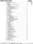
Contents
1. Precautions ............................................................................................................1
2. Product Outline......................................................................................................4
3. Features..................................................................................................................5
4. Specifications ........................................................................................................6
5. Front and Rear Panels...........................................................................................8
6. Operation..............................................................................................................11
6.1 The Setup of Output Function ...................................................................11
6.2 The Setup of Frequency.............................................................................11
6.3 The Setup of Amplitude .............................................................................11
6.4 The Setup of Offset ....................................................................................12
6.5 The Setup of Arbitrary-Wave Compiler.....................................................12
6.6 Deleting the Data of Arbitrary Wave .........................................................13
6.7 The Setting of STOR Button ......................................................................13
6.8 The Setting of RECL Button ......................................................................14
6.9 The SHIFT Key and Function Keys ...........................................................14
6.10 Setup of LIN or LOG Sweep.....................................................................15
6.11 Setup of AM Modulation ..........................................................................16
6.12 Setup of FM Modulation...........................................................................17
6.13 Setup of PM Modulation...........................................................................18
6.14 The Commands of GPIB Serial Interface................................................18
6.15 Syntax and Commands:...........................................................................22
6.16 The Examples of the Communication Interface Software.....................24
7. Adjustment and Correction ................................................................................27
7.1 Preparation .................................................................................................27
7.2 Adjusting Clock ..........................................................................................27
7.3 Adjusting the DC of Frequency Double....................................................27
7.4 Adjusting D/A Ref .......................................................................................27
7.5 Adjusting the Bandwidth ...........................................................................27
7.6 Adjusting the Filter.....................................................................................28
7.7 Adjusting Harmonic Distortion..................................................................28
7.8 Calibrating by Software .............................................................................28
7.9 Checking Frequency Accuracy .................................................................32
7.10 Checking the Amplitude ..........................................................................32
.8. The Block Diagram and Description of the System.........................................35
Appendix 1 Commands of IEEE488.2………………………………………………..38
Appendix 2 RS-232 Wiring Configuration…………..………………………………43
i
EC Declaration of Conformity
We
GOOD WILL INSTRUMENT CO., LTD.
(1) NO. 95 - 11, Pao Chung Rd., Hsin-Tien City, Taipei Hsien, Taiwan
(2) Plot 522, Lorong Perusahaan Baru 3, Prai Industrial Estate, 13600 Prai,
Penang, Malaysia declare, that the below mentioned product
SFG-830
is herewith confirmed to comply with the requirements set out in the Council Directive on the
Approximation of the Law of Member States relating to Electromagnetic Compatibility
(89/336/EEC,92/31/EEC,93/68/EEC) and Low Voltage Equipment Directive(73/23/EEC).
For the evaluation regarding the Electromagnetic Compatibility and Low Voltage Equipment
Directive, the following standards were applied:
EN50081-1: Electromagnetic compatibility EN50082-1: Electromagnetic compatibility (1992)
Generic emission standard
(1992)
Generic immunity standard
Part 1: Residential, commercial and light
Part 1: Residential, commercial and light industry
industry
Conducted
EN 55022
class A
Electrostatic Discharge IEC 1000-4-2
(1995)
Emission
Radiated Emission
(1994)
Radiated Immunity
IEC 1000-4-3
(1995)
Current Harmonics EN 61000-3-2 +A12 (1996) Electrical Fast
IEC 1000-4-4
(1995)
Transients
Voltage
EN 61000-3-3
(1995)
Surge Immunity
IEC 1000-4-5
(1995)
Fluctuations
-----------------------------------Voltage Dip/Interruption EN 61000-4-11
(1994)
EN50081-2: Electromagnetic compatibility (1993)
Generic emission standard
Part 2: Industrial Environment
Conducted Emission EN 55011
class A
Radiated Emission
(1991)
Low Voltage Equipment Directive 73/23/EEC
Low Voltage Directive
EN
61010-1:(1993)+A2:(1995)
SFG-830
p.1
1. Precautions
SFG-830 is especially designed for safe operation. It has passed rigorous tests of
inclement environment to ensure its reliability and good condition.
The following precautions are recommended to insure your safety and the best
condition of this equipment.
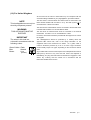
(1) Safety Terms and Symbols
The following terms and symbols may appear in this manual:
!
!
This statement identifies conditions or practices that could
result in injury or loss of life.
This statement identifies conditions or practices that could
CAUTION
result in damage to this product or other properties.
WARNING
The following terms and symbols may appear on the product:
This term indicates an immediately accessible injury hazard.
DANGER
This term indicates that an injury hazard may occur, but is
WARNING
not immediately accessible.
This term indicates potential damage to this product or other
CAUTION
properties.
!
DANGER
High voltage
Protective
Conductor
Terminal
ATTENTION
refer to manual
Double
Insulated
DANGER
Hot surface
Earth
Ground
Terminal
(2) Do not place any heavy objects on the instrument under any circumstances.
(3) Disassembling the instrument
Due to the precision of this instrument, all the disassembling, adjusting, and
maintenance should be performed by a professional technician. If the instrument
have to be opened or adjusted under some unavoidable conditions, it should be
carried out by a technician who is familiar with SFG-830. Once there is any
abnormality, please contact our company or the agency near you.
(4) Power Supply
AC input should be within the range of line voltage±10%, 50/60Hz. To prevent the
instrument from burning up, be sure to check the line voltage before turning on
power.
SFG-830
p.1
(5) Grounding
!
WARNING
To avoid electrical shock, the power cord protective grounding
conductor must be connected to ground.
SFG-830 can be operated only with an earth grounded AC power cord that connects
the case and ground well. This is to protect the user and the instrument from the risk
of shock hazard.
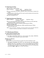
(6) Fuse Replacement
!
WARNING
For continued fire protection, replace fuse only with the
specific type and rating. Disconnect the power cord before
replacing fuse.
The fuse blows only if there is anything wrong with the instrument, and SFG-830 will
stop working under this situation. Please check the cause of it, then replace an
proper fuse as listed below. Be sure to use the correct fuse before changing the
applying voltage.
90V ~ 132V
: T 0.8A/250V
198V ~ 250V
: T 0.5A/250V
F101-102
: T1A/250V
F103-104
: T2A/250V
Check the line voltage setting on the rear panel. If the line voltage setting does not
match the one of your area, change the line voltage setting according to the following
steps:
1.Open the cover of AC socket with flat-blade screwdriver.
2.Remove cam drum, rotate to correct selection and reinsert.
(7) Cleaning the Cabinet
Disconnect the AC power cord before cleaning the instrument.
Use a soft cloth dampened in a solution of mild detergent and water. Do not spray
cleaner directly onto the instrument, since it may leak into the cabinet and cause
damage.
Do not use chemicals containing benzing, benzne, toluene, xylene, acetone, or
similar solvents.
(8) Operation environment
Indoor use
Altitude up to 2000m
Temperature to satisfy the specification :
Operating temperature :
Storage temperature :
Relative humidity :
Installation category:
Pollution degree:
18oC ~ 28oC (+64.4oF ~ +82.4oF)
0oC ~ 40oC (+32oF ~ +104oF)
-10oC ~ 70oC (+14oF ~ 158oF)
up to 90% when 0oC~35oC;
up to 70% when 35oC~40oC
II
2
(9) Place SFG-830 in a location of satisfied environment as stated above free from
dust, direct exposition of sunlight, and strong effect of magnetic fields.
p. 2
SFG-830
(10) For United Kingdom
As the colours of the wires in mains leads may not correspond with the
coloured markings identified in your plug/appliance, proceed as follows:
NOTE
This lead/appliance must only be
wired by competent persons.
The wire which is coloured Green and Yellow must be connected to the
or
Earth terminal marked with the letter E or by the earth symbol
coloured Green or Green and Yellow.
The wire which is coloured Blue must be connected to the terminal which
WARNING
THIS APPLIANCE MUST BE
EARTHED
is marked with the letter N or coloured Blue or Black.
The wire which is coloured Brown must be connected to the terminal
marked with the letter L or P or coloured Brown or Red.
If in doubt, consult the instructions provided with the equipment or contact
IMPORTANT
The wires in this lead are
coloured in accordance with the
following codes:
the supplier.
This cable/appliance should be protected by a suitably rated and
approved HBC mains fuse; refer to the rating information on the
equipment and/or user instructions for details.
As a guide, cable of
0.75mm2 should be protected by a 3A or 5A fuse. Larger conductors
Green/Yellow :Earth
Blue
:Neutral
:Live
Brown
(Phase)
would normally require 13A types, depending on the connection method
used.
Any moulded mains connector that requires removal/replacement must be
destroyed by removal of any fuse and fuse carrier and disposed of
immediately, as a plug with bared wires is hazardous if engaged in a live
socket. Any re-wiring must be carried out in accordance with the
information detailed in this section.
SFG-830
p.3
2. Product Outline
The frequency synthesis method applied by SFG-830 is Direct Digital Synthesis
(DDS), a new technique that generates stable output frequency with extraordinary
resolution.
Unlike SFG-830, traditional frequency synthesized function generators typically use
Phase Locked Loop (PLL) techniques. In order to synthesize frequencies, PLL should
be high-resolution (up to 1:106 in general) and needs a stable frequency to be
reference. Due to the utilization of dynamic loop filter, problems such as poor phase
jitter and frequency switching response may occur when running the PLL system.
As in generating waveforms, PLL needs a wave-shaping circuit with an address
counter that controlled by a variable frequency clock. The counter addresses
memory locations in a waveform RAM, and the RAM output is converted by a high
speed digital-to-analog converter (DAC) to produce an analog output signal. Problems
like poor phase jitter and transient response may arise here as well.
Although DDS also generates analogue waveforms by way of the waveform RAM and
high speed DAC, it does not have the problems as PLL does due to the use of fixed
frequency clock (fs). Besides, the resolution of DDS is higher than that of PLL’s.
DDS’s resolution is fs/2k where the digit of the control frequency word (K), which is
more than 32bits in general, decides the quality of it.
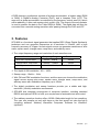
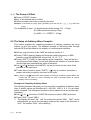
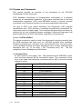
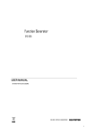
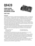
Graph1 indicates the fundamental construction of a DDS frequency synthesizer.
K
(Frequency Control Word)
32
Accumulator
32
System
Clock
fs
Register
32
24
ROM or RAM
12
Digital / Analog
Converter
p. 4
SFG-830
Lowpass Filter
fo
A DDS frequency synthesizer consists of a phase accumulator, a lookout table (ROM
or RAM), a Digital-to-Analog Converter (DAC), and a Lowpass Filter (LPF). The
amount in a phase accumulator is controlled by the frequency control word (K), which
will be added by 1 after each system clock cycle(=1/fs). The output of the accumulator
is used to position the data in the Table ROM (or RAM). The digital data will then be
converted into a smooth analog waveform after passing through the DAC and LPF.
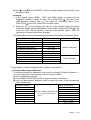
3. Features
SFG-830 is a functional signal generator that applies DDS (Direct Digital Synthesis)
technique and can generate frequencies at a resolution of 20mHz, with a high
frequency accuracy of 10ppm. Its main signal source can generate waveforms of sine
wave, square wave, triangle wave, ramp wave, and arbitrary wave.
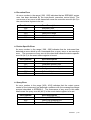
The output frequency range and resolution of each waveform are:
Waveforms
Frequency Range
Resolution
20mHz ~ 30MHz
20mHz
Triangle wave, ramp wave
100mHz ~ 100kHz
10mHz
Arbitrary wave
42.949600MHz/N, where N=8,10,12,…,215
Sine wave, square wave
The depth of AM modulation : 0% ~ 100%
Sweep range : 10mHz ~ 1kHz
With FM and PSK modulation functions, and the users can choose the modulation
signal source among sine wave, square wave, triangle wave, ramp wave, and
arbitrary wave with modulation frequency up to 10kHz.
The digital modulation and sweep functions provide you a stable and highresolution (10mHz) modulation environment.
SFG-830 has complete environment of computer interface, including standard
RS232 and optional GPIB, to fulfill your requirement of automatic test and control.
The arbitrary waveform function offers 12000×12bits data length for free compiling.
The user can compile not only with keys on the front panel, but also through a
compiling software “Arbitrary Waveform Composer Software for Windows”
(optional).
SFG-830
p.5
4. Specifications
Output Function
Frequency Range
Frequency
Resolution
Sine, Triangle, Ramp, Square, Sync Output, Arbitrary
Sine
20mHz ~ 30MHz
Square
20mHz ~ 30MHz
Triangle
100mHz ~ 100kHz
Ramp
10mHz ~ 100kHz
Sine / Square
20mHz
Triangle / Ramp
10mHz
Frequency
Accuracy
± 10 ppm
Frequency Aging
± 5 ppm / year
Output Impedance
Source Impedance
50Ω ± 10%
Range
10mV~10Vp-p (into 50Ω) 8 amplitude
ranges
| Vac peak | + | Vdc | < 5V
Resolution
3 digits
± 0.5dB +5mV (Sine out)
Amplitude
Accuracy
± 12% +5mV (Square out)
± 5% +5mV (Triangle out)
± 5% +5mV (Arbitrary out)
Range
DC Offset
Sync Output
Sine Output
Square Output
Triangle and Ramp
p. 6
SFG-830
± 5V (into 50Ω)
| Vac peak | + | Vdc | < 5V
Resolution
3 digits
Accuracy
± 1.5% of setting + 1mV
Sync Output
TTL levels
Sync Fan-out
> 10 TTL load
Harmonics
DC
0.1MHz
1MHz
10MHz
~
~
~
~
100kHz
1MHz
10MHz
30MHz
:
:
:
:
-50dBc
-40dBc
-30dBc
-25dBc
Rise / Fall Time
≤ 15ns
Overshoot
≤ 5% (at full scale output)
Asymmetry
± 1% of period + 4ns
Linearity
± 0.1% of full scale output
Arbitrary
Waveforms
Sweep
Sample Rate
42.949600MHz/N, N=8, 10, 12,…215
Waveform Length
12,000 points max.
Vertical Resolution
12 bits
Sweep Function
Line or Log
Sweep Range
20mHz ~ 30MHz
Sweep Time
Modulation Span
0.01S ~ 1000S
External, Internal
(sine, triangle, ramp, square)
10mHz ~ 10kHz (Internal)
50kHz (max. external)
0 ~ 100%
Ext. Input
±5V for 100% modulation
Ext. Input Impedance
100 kΩ
FM Function
Sine, Triangle, Ramp, Square
Modulation Rate
10mHz ~ 10kHz
Modulation Span
30mHz (100kHz for triangle, ramp)
PSK Span
360 degrees
AM Modulation
Function
Modulation Rate
Modulation
Interface
Accessories
Power Source
Modulation Rate
20Hz ~ 10kHz
RS232
GPIB interface (optional)
Arbitrary waveform composer software for Windows(optional)
GTL-101 × 1,
Instruction Manual × 1
100/120/220/ 240V AC ±10%,
50/60Hz
Dimensions
214 (W) × 89 (H) × 370 (D) mm
Weight
Approx. 5kg
SFG-830
p.7
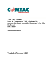
5. Front and Rear Panels
Front Panel
p. 8
SFG-830
1
POWER button
:
Push in the button, then the power will be supplied and the
display will light up. The power is off when push the button
again to the flat position.
2
UNIT keys
:
In ‘Normal’ mode, these keys are used to assign the unit and
to set the entered value. For example, you can use dBm,
Vrms, and Vpp to set the output amplitude. They can be used
to set frequency (MHz, kHz, Hz), OFFSET, PHASE, etc.
In STOR or RECL modes, they are used as ‘Enter’.
3
SHIFT key
:
Press this key to set the shift mode, and the SHIFT LED will
light up. For example, press [SHIFT] + [DEFAU] can recall the
default value of this instrument.
4
ENTRY keys
:
[ 0 ] ~ [ 9 ], [ . ], and [ ± ] keys are used to input value. A unit
key should be pressed to set the entered value.
[ CLR ] key is used to delete the entered value entirely and
bring back the previous value.
[ STOR ] key stores the settings into memory.
[ RECL ] key recalls the system settings from memory.
5
SWEEP/
MODULATE keys
:
These keys control the functions of sweep and modulation.
[ ] and [ ] keys select the carrier waveform.
[AM], [FM], and [PM] keys set the mode of modulation.
[ LIN ] and [ LOG ] keys set the sweep method.
[ MOD ON/OFF ] initiates sweep or modulation function.
As to the functions of [STAR], [STOP], [SPAN], and [RATE]
keys, please refer to the instruction in Chapter 6.
6
MODIFY keys
:
These keys set the size and the increasing or decreasing
mode of steps.
7
FUNCTION keys
:
These keys controls the output functions.
[ ] and [ ] keys select the output signal from arbitrary wave
(ARB), sine wave, triangle wave, etc.
[ FREQ ] key sets the frequency of output.
[ AMPL ] key sets the amplitude of output.
[ OFFSET ] key sets the DC level of output.
[ PHASE ] key sets the phase in PSK modulation mode.
8
MAIN OUTPUT BNC
:
This is the BNC connector that outputs all main signals.
Output resistance is 50Ω.
9
SYNC OUTPUT BNC
:
This is the synchronous output BNC connector that outputs a
TTL-level signal.
10
Interface LEDs
:
These LEDs indicate the current status when operating with
the GPIB interface bus.
11
Parameter display
:
This 11-digit display presents the parameter values and
information about the current status.
12
Unit/Function LEDs
:
These LEDs indicate the unit of the figures on display and the
functions that are currently being used.
SFG-830
p.9
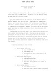
Rear Panel
p. 10
SFG-830
1
Power Entry model
: This is the AC power input terminal. AC input should be within
the range of line voltage±10%, 50/60Hz.
2
3
Sweep/Modulation
output
: This terminal outputs the modulated waveform that is
EXT AM Input
: This is the BNC connector for amplitude modulation input. The
synchronous with the Sweep / Modulation function of this
instrument (±5Vpp Max.)
modulation index is 100% when ±5 is input. The input
resistance is 100kΩ.
4
GPIB connector
: The optional GPIB (IEEE488.2 and SCPI) communication
interface should be plugged here.
5
RS232 connector
: This is the port of serial RS232 interface. The DCE and Baud
rate is among 300 ~ 19.2k.
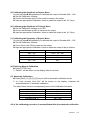
6. Operation
6.1 The Setup of Output Function
Use the two buttons [ ] or [ ] in the FUNCTION column on front panel to select
an output waveform. Available waveforms are arranged in sequence SINE,
SQU, TRIG, RAMP, and ARB (from left to right).
6.2 The Setup of Frequency
n Press [ FREQ ] button.
o Key in the desired value of frequency.
p Select a proper unit-button to specify the value.
Example: To set frequency at 250Hz, press [ FREQ ] first; then key in [ 2 ], [ 5 ], [ 0 ], and press
[ Hz ].
The frequency range of waves:
Sine
0.02Hz ∼ 30MHz
Square
0.02Hz ∼ 30MHz
Triangle
0.1Hz ∼ 100kHz
RAMP
0.1Hz ∼ 100kHz
ARB
42.949600MHz/N, N=8, 10,12,…215
6.3 The Setup of Amplitude
n Press [ AMPL ] button.
o Key in the desired value of amplitude.
p Select a proper unit-button to specify the value.
Example: To set amplitude at 5Vpp, press [ AMPL ] first, then key in [ 5 ] and press [ Vpp ].
SFG-830
p.11
6.4 The Setup of Offset
n Press [ OFFSET ] button.
o Key in the desired value of offset.
p Select a proper unit-button to specify the value.
Example: To set offset at 1.2Vpp, press [ OFFSET ] first, then key in [ 1 ], [ . ], [ 2 ], and press
[ Vpp ].
The limitations of input : (1) Amplitude should be among 0.01 ~ 10Vpp.
(2) Offset should be among ±5Vpp.
(3) AMPL + 2 × OFFSET ≤ 10Vpp.
6.5 The Setup of Arbitrary-Wave Compiler
This section explains the compiling procedure of arbitrary waveform by using
buttons on the front panel. The detailed example of delivering data through
optional GPIB will be stated in the chapter of communication interface.
n Set the output function to be “ARB” as stated in section 6.1.
o Press [ FREQ ] and the display will show the reading frequency of ARB
function (range 42.9496MHz/N, where N=8, 10, 12,…215).
p Press [ SHIFT ] [ ARB ] to start arbitrary-wave compilation. There will be two
set of figures on the display, the left one indicates the number of a certain point,
and the right one represents the value of that point.
q Use [ ] or [ ] buttons in the MODIFY column to check out the value of the
previous or the next point.
r To edit value of a point, press [ SHIFT ] + [ ]; key in numbers, and select a
proper unit-button to specify new value of the point.
Note: [ SHIFT ] and [ ] buttons are used together for switching the blinking state between the
number and the value of a point. Following the order of arranged points to compile
arbitrary-wave is necessary.
Example of Compiling Arbitrary-Wave
The following example will guide you to proceed the compilation of arbitrary-wave.
Here, 8 points (values are identified as 0, 400, 800, 1200, 0, 0, 0, 0 in an order)
will be compiled. The changes of waveform will be observed via an oscilloscope.
Procedure :
n Use [ ] or [
] buttons in FUNCTION column to select [ ARB ] waveform.
o Press [ SHIFT ] and [ ARB ].
ª The display will show “arb edit” for a while then shows “0001 2047”, which
indicates that you are in the compiling mode and the value of the first point is
2047. The number “0001” will be blinking.
p. 12
SFG-830
p Press [ SHIFT ] and [ ] to make the right-hand figures “2047” blinking; then
key in [ 0 ] and press [ Hz ] to change the value of the first point from 2047 to 0.
q Press [ SHIFT ] and [ ] again to make the left-hand figures “0001” blinking.
r Press [ ] to compile the second point.
ª The display will show “0002 -2047”, which indicates the value of the second
point is -2047. The number “0002” is blinking.
s Press [ SHIFT ] and [ ] to make “-2047” blinking; then key in [ 4 ], [ 0 ], [ 0 ],
and press [ Hz ] to change the value of the second point from -2047 to 400.
t Repeat step q to s to complete the compilation of other points.
u Press [ FREQ ] and set the reading frequency according to the frequency
setting procedure.
The limitations of input:
(1) Compiling points: up to 12000 points
(2) Compiling value : -2047 ~ +2047
(3) Reading frequency : 42.949600MHz/N, where N=8, 10, 12…215
6.6
Deleting the Data of Arbitrary Wave
n Press [ SHIFT ] and [ ARB ].
ª The display will show “arb edit”, then shifts to compiling mode.
o Press [ SHIFT ] and [ ARB ] again.
ª The display will show “clr arb fnc”, then shifts to the mode of deleting arbitrary
wave.
p Press any unit-button.
ª The display will show “arb cleared” for a few seconds, then shows “clr arb
fnc”, which indicates that all the data of the arbitrary wave have been deleted.
q Press [ SHIFT ] and [ ARB ] to compile again.
6.7 The Setting of STOR Button
The STOR button is used to save the setup parameters of the instrument into its
memory; numbers can be selected from 0 to 9, i.e., up to 10 groups.
n Push [ STOR ] button.
o Key in a number from 0 to 9 to indicate the number .
p Press any button from [ DEG/ % ], [ mHz/dBm ], [ kHz/Vrms ], or [ Hz/Vpp ] to
complete.
Example: To save a parameter to the RAM of group #5, press [ STOR ] first. Then key in [ 5 ] and
press [ Hz ].
SFG-830
p.13
6.8 The Setting of RECL Button
The RECL button can retrieve the parameters saved in the RAM.
n Push [ RECL ] button.
o Key in the number of the group that you want to retrieve the parameters from.
p Select a button from [ DEG/ % ], [ mHz/dBm ], [ kHz/Vrms ], or [ Hz/Vpp ] to
complete.
Example: To recall a parameter from the memory of group #5, press [ RECL ] first. Then key in
[ 5 ] and press [ Hz ].
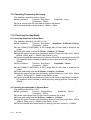
6.9 The SHIFT Key and Function Keys
SHIFT button is used to enable the secondary function of certain function keys
that with blue symbols printed above. The SHIFT LED will be on after pressing
the [ SHIFT ] button. At this time, only the buttons with blue symbols are workable.
To release the SHIFT function, press [ SHIFT ] again.
The Secondary Functions
1. [ SHIFT ] + [ SWP CF ]
Displays sweep center frequency.
2. [ SHIFT ] + [ DEFAU ]
Gets back to the default status of SFG-830.
3. [ SHIFT ] + [ ARB ]
Sets up arbitrary-wave compiler.
4. [ SHIFT ] + [ DATA ]
Displays the last 256 byte of ASCII data received
by SFG-830.
5. [ SHIFT ] + [ GPIB ]
Sets up GPIB on/off status by using the arrows
buttons in MODIFY column.
6. [ SHIFT ] + [ ADDR ]
Sets up GPIB address (range from 0 to 30).
7. [ SHIFT ] + [ LOCAL ]
Switches RMT status to LOCAL status.
8. [ SHIFT ] + [ RS232 ]
Sets up RS232 on/off status and its BAUD RATE.
9. [ SHIFT ] + [
]
Switches the blinking state between the number
and the value of a point for inputting data while
compiling the arbitrary wave.
10. [ SHIFT ] + [
]
Switches the blinking state between the number
and the value of a point for inputting data while
compiling the arbitrary wave.
p. 14
SFG-830
6.10 Setup of LIN or LOG Sweep
SFG-830 can adopt frequency to sweep its function output for triangle and ramp
waves. The type of sweep can be set as linear or log sweep.
n Select a main waveform by [ ] or [
] button in FUNCTION column.
o Set triangle or ramp sweep mode by [ ] or [
] button in SWEEP /
MODULATION column.
p Press [ LIN S ] or [ LOG S ] button.
q Press [ RATE ] to set up sweep RATE/TIME (range 0.001Hz ~ 1kHz).
r Press [ STAR ] and [ STOP ] buttons to set up the starting and ending sweep
frequency. This can also be done by pressing [ SWP CF ] and [ SPAN ].
sPress [ MOD ON/OFF ] to initiate sweeping.
Note: Please refer to the example in next page for the setup of LIN Sweep.
Example of the Setup of LIN Sweep
To set the following conditions:
Output function : sine.
Sweep waveform : ramp.
Start frequency : 1kHz.
Stop frequency : 10kHz.
Speed 1 second.
Procedure:
] button in FUNCTION column to select SINE waveform.
n Use[ ] or [
] button in SWEEP/MODULATION column to select
o Then use [ ] or [
RAMP waveform.
p Press [ LIN S ] button.
q Press [ RATE ], [ 1 ], [ Hz ].
r Press [ STAR ], [ 1 ], [ kHz ] first; then press [ STOP ], [ 1 ], [ 0 ], [ kHz ].
s Press [ MOD ON/OFF ] to start sweeping.
Example of the Setup of LOG Sweep
To set the following conditions:
Output function : sine.
Sweep waveform : ramp.
Start frequency : 1kHz.
Stop frequency : 10kHz.
Speed 0.1 second.
Procedure:
] button in FUNCTION column to select SINE waveform.
n Use [ ] or [
o Then use [ ] or [
] button in SWEEP/MODULATION column to select
RAMP waveform.
p Press [ LOG S ] button.
q Press [ RATE ], [ 1 ], [ 0 ], [ Hz ].
r Press [ STAR ], [ 1 ], [ kHz ] first; then press [ STOP ], [ 1 ], [ 0 ], [ kHz ].
s Press [ MOD ON/OFF ] to start sweeping.
SFG-830
p.15
Note:
c Different sequence of the steps taken will not make any change on the execution and
the result.
d The bandwidth [SPAN] = stop frequency - start frequency
e The center frequency [ SWP CF ] = [(stop frequency + start frequency)/2]
f The start frequency [ STAR ] = center frequency of the sweep - bandwidth/2
g The stop frequency [ STOP ] = center frequency of the sweep + bandwidth/2
h The start and stop frequencies can be freely set according to the preference of different
users.
i SFG-830 can output waveform that is synchronized with its sweep function. In the
example of setting up LIN sweep, the Sweep/modulation output terminal on the rear
panel will output the waveform of ramp/1Hz.
6.11 Setup of AM Modulation
The AM modulation function offers sine, square, triangle, ramp, and arbitrary
signals.
n Select a waveform by [ ] or [
] button in FUNCTION column.
o Use [ ] or [
] button in SWEEP / MODULATION column to select a
modulation signal from sine, square, triangle, ramp, or ARB.
p Press [ AM ] button.
q Press [ RATE ] to set up sweep RATE/TIME (range 0.001Hz ~ 10kHz).
r Press [ SPAN ] to set the Modulation Depth (range 100%).
s Press [ MOD ON/OFF] to start performing modulation.
Example of the Setup of AM Modulation
To set the following conditions:
Modulation waveform : sine.
Frequency : 10kHz.
Modulation rate : 100Hz.
Signal : sine/100Hz AM modulation.
Procedure:
] button in FUNCTION column to select SINE waveform.
n Use [ ] or [
o Press [ FREQ ], [ 1 ], [ 0 ], [ kHz ] buttons to set the frequency of the wave.
p Then use [ ] or [
] button in SWEEP/MODULATION column to select
SINE waveform.
q Press [ AM ].
r Press [ RATE ], [ 1 ], [ 0 ], [ 0 ], [ Hz ].
s Press [ SPAN ], [ 1 ], [ 0 ], [ 0 ], [ % ] to set the modulation depth.
t Press [ MOD ON/OFF ] to start performing modulation.
Note:
c Different sequence of the steps taken will not make any change on the execution and
the result.
d SFG-830 has both internal and external modulation functions.
p. 16
SFG-830
e The input voltage of external modulation is -5V ~ +5V.
* If the input voltage is between 0V ~ +5V, the AM modulation will be the common
modulation.
* If the input voltage is between -5V ~ +5V, the AM modulation will be double sideband
suppressed carrier (DSBSC).
f SFG-830 can output waveform that is synchronized with its AM modulation signal. In the
above example, the Sweep/modulation output terminal on the rear panel will output the
waveform of SINE/100Hz.
g The compiling of arbitrary wave should be carried out via the communication interface.
Please refer to Example 2 in section 6.16.
6.12 Setup of FM Modulation
The FM modulation function offers sine, square, triangle, ramp, and arbitrary
signals.
n Select a waveform by [ ] or [
] button in FUNCTION column.
o Use [ ] or [
] button in SWEEP / MODULATION column to select a
modulation signal from sine, square, triangle, ramp, or ARB.
p Press [ FM ] button.
q Press [ RATE ] to set up sweep RATE/TIME (range 0.001Hz ~ 10kHz).
r Press [ SPAN ] to set the Frequency Span (0.001Hz~30MHz for sine and
square; 100kHz for triangle, ramp and arb).
s Press [ MOD ON/OFF] to start performing modulation.
Example of the Setup of FM modulation
To set the following conditions:
Main waveform : sine.
Span : 10kHz
Main frequency : 100kHz.
Modulation signal : sine/1kHz FM modulation.
Procedure:
] button in FUNCTION column to select SINE waveform.
n Use [ ] or [
o Press [ FREQ ], [ 1 ], [ 0 ], [ 0 ], [ kHz ] buttons to set the frequency of the wave.
p Use [ ] or [
] button in SWEEP/MODULATION column to select SINE
waveform.
q Press [ FM ].
r Press [ RATE ], [ 1 ], [ kHz ].
s Press [ SPAN ], [ 1 ], [ 0 ], [ kHz ] to set span.
t Press [ MOD ON/OFF ] to start performing modulation.
Note:
c Different sequence of the steps taken will not make any change on the execution and
the result.
d SFG-830 can output waveform that is synchronized with its FM modulation signal. In the
above example, the Sweep/modulation output terminal on the rear panel will output the
waveform of SINE/1kHz.
e The compiling of arbitrary wave should be carried out via the communication interface.
Please refer to Example 3 in section 6.16.
SFG-830
p.17
6.13 Setup of PM Modulation
SFG-830 use 256PSK (Phase Shift Key in) to generate PM modulation.
n Use [ ] or [
] button in FUNCTION column to select SINE waveform.
o Press [ PM ] button.
p Press [ RATE ] to set up sweep RATE/TIME (range 20Hz ~ 10kHz).
q Press [ PHASE ] to set Phase Span ( range 0o ~ 360o).
r Press [ MOD ON/OFF] to start performing modulation.
Example of the Setup of PM Modulation
To set the following conditions:
Main waveform : sine.
Frequency : 10kHz.
Rate : 100Hz.
Angle : 100o PSK modulation.
Procedure:
n Use [ ] or [
] button in FUNCTION column to select SINE waveform.
o Press [ FREQ ], [ 1 ], [ 0 ], [ kHz ] buttons to set the frequency of the wave.
p Press [ PM ].
q Press [ RATE ], [ 1 ], [ 0 ], [ 0 ], [ Hz ].
r Press [ PHASE ], [ 1 ], [ 0 ], [ 0 ], [ DEG / % ] to set the phase to be 100o.
s Press [ MOD ON/OFF ] to start performing modulation.
Note: Different sequence of the steps taken will not make any change on the execution and the
result.
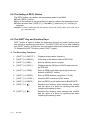
6.14 The Commands of GPIB Serial Interface
This section explains the GPIB commands that applied by SFG-380. All the 69
commands, including 54 instrument commands, and 15 IEEE488.2 common
commands, correspond to the SCPI syntax. The syntax, function, and parameter
of all the commands are listed below. It is helpful for you to control the remote
instrument through either GPIB or RS232.
Example:
ibwrt “> IDN ?”
ibwrt “ SOUR : FREQ : SYNT 1000”
ibwrt “ SOUR : FREQ : STAR 1000 ; : SOUR : FREQ :
= ibwrt “ SOUR : FREQ : STAR 1000 ; STOP 10000”
p. 18
SFG-830
STOP 10000”
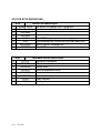
(1) Common Commands of IEEE488.2
Command
Function
Parameter
*CLS
Clear status command
Nil
*ESE
Standard event status enable command
Numerical data
*ESE?
Standard event status enable query
Nil
*ESR?
Standard event status register query
Nil
*IDN?
Identification query
Nil
*OPC
Operation complete command
Numerical data
*OPC?
Operation complete query
Nil
*RCL
Recall command
Integer among 0 ~ 9
*RST
Reset command
Nil
*SAV
Save command
Integer among 0 ~ 9
*SRE
Service request enable command
Numerical data
*SRE?
Service request enable query
Nil
*STB?
Read status byte query
Nil
*TST?
Self-test query
Nil
*WAI
Wait-to-continue command
Nil
Note : c The range of numerical data is 0 ~ 255.
d For more details, please refer to appendix 1.
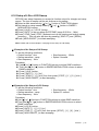
(2) Commands of the Instrument
Command
Function
Parameter
SYSTem:ERR?
Check the type of error messages
Nil
SOURce:FUNCtion:SINusoid
Select sine waves
Nil
SOURce:FUNCtion:SQUare
Select square waves
Nil
SOURce:FUNCtion:TRIangle
Select triangle waves
Nil
SOURce:FUNCtion:RAMP
Select ramp waves
Nil
SOURce:FUNCtion:ARBitrary
Select arbitrary waves
Nil
SOURce:FUNCtion:WAVEform?
Check the present waveform
Nil
SOURce:FREQuency:SYNThesis
Set the frequency of synthetic waves
SOURce:FREQuency:SYNThesis?
Check the frequency of synthetic waves
Numeric data
Nil
SFG-830
p.19
Commands of the Instrument (cont.)
Command
p. 20
Function
Parameter
SOURce:FREQuency:CENTer
Set center frequency of synthetic waves Numeric data
SOURce:FREQuency:CENTer?
Check the center frequency of synthetic
waves
SOURce:FREQuency:SPAN
Set span frequency of synthetic waves
SOURce:FREQuency:SPAN?
Check the span frequency of synthetic
waves
SOURce:FREQuency:STARt
Set the value of the initial frequency
SOURce:FREQuency:STARt?
Check the value of the initial frequency
SOURce:FREQuency:STOP
Set the value of the ending frequency
SOURce:FREQuency:STOP?
Check the value of the ending frequency
SOURce:SWEep:SPACing
Set the method of sweep
SOURce:SWEep:SPACing?
Check the method of sweep
Nil
SOURce:MODulation:STATe
Enable modulation function
ON/OFF or 0/1
SOURce:MODulation:STATe?
Check if in modulation mode
Nil
SOURce:PHASe:ADJust
Set the data of phase
SOURce:PHASe:ADJust?
Check the data of phase
SOURce:AMPLitude:LEVel
Set the value of output amplitude
SOURce:AMPLitude:LEVel?
Check the value of output amplitude
SOURce:AMPLitude:STATe
Get in amplitude mode
SOURce:AMPLitude:STATe?
Check if in amplitude mode
SOURce:AMPLitude:UNIT
Set the unit of output amplitude
SOURce:OFFSet:LEVel
Set the voltage of offset
SOURce:OFFSet:LEVel?
Check the voltage of offset
SOURce:OFFSet:STATe
Get in bias mode
SOURce:OFFSet:STATe?
Check if in bias mode
SOURce:SWEep:RATE
Set the rate of modulation
SOURce:SWEep:RATE?
Check the rate of modulation
SOURce:FUNCtion:SOURce
Set the waveform of modulation
SOURce:FUNCtion:SOURce?
Check the waveform of modulation
SOURce:FUNCtion:AM:STATe
Set AM modulation
SOURce:FUNCtion:AM:STATe?
Check if in AM modulation
SFG-830
Nil
Numeric data
Nil
Numeric data
Nil
Numeric data
Nil
LINear or LOG
Numeric data
Nil
Numeric data
Nil
ON/OFF or 0/1
Nil
VPP, VRMS or
DBM
Numeric data
Nil
On/OFF or 0/1
Nil
Numeric data
Nil
1,2,3,4,5
Nil
ON/OFF or 0/1
Nil
Commands of the Instrument (cont.)
Command
Function
Parameter
SOURce:FUNCtion:FM:STATe
Set FM modulation
ON/OFF or 0/1
SOURce:FUNCtion:FM:STATe?
Check if in FM modulation
SOURce:FUNCtion:PM:STATe
Set PM modulation
SOURce:FUNCtion:PM:STATe?
Check if in PM modulation
SOURce:FUNCtion:AM:SOURce
Set the waveform of AM modulation
SOURce:FUNCtion:AM:SOURce?
Check the waveform of AM modulation
SOURce:FUNCtion:FM:SOURce
Set the waveform of FM modulation
SOURce:FUNCtion:FM:SOURce?
Check the waveform of FM modulation
SOURce:FUNCtion:PM:SOURce
Set the waveform of PM modulation
SOURce:FUNCtion:PM:SOURce?
Check the waveform of PM modulation
SOURce:FUNCtion:AM:DEPTh
Set the depth of AM modulation
SOURce:FUNCtion:AM:DEPTh?
Check the depth of AM modulation
SOURce:FUNCtion:LDWF
Set the point of arbitrary wave in carrier
Numeric data
wave mode
SOURce:FUNCtion:AMOD
Set the point of arbitrary wave in audio
Numeric data
frequency
SOURce:FUNCtion:FM:DEViation
Set the span of FM modulation
SOURce:FUNCtion:FM:DEViation?
Check the span of FM modulation
Nil
ON/OFF or 0/1
Nil
1,2,3,4,5
Nil
1,2,3,4,5
Nil
1,2,3,4,5
Nil
Numeric data
Nil
Numeric data
Nil
NOTE : c All of the above commands correspond with the SCPI Standard.
d You can key in the whole line or just the capital letters of each command.
e The numeric data should be within the suitable range of each command.
For example: The range of a synthetic wave is 0.01Hz ~ 30MHz.
f Parameters ON and 0 mean that the input mode is on; OFF and 1 mean that the input
mode is off.
g The meaning of parameters 1 ~ 5 are: 1 : Sine wave
2 : Square wave
3 : Triangle wave
4 : Ramp wave
5 : Arbitrary wave
SFG-830
p.21
6.15 Syntax and Commands:
This section provides an overview of the commands for the SFG-830
Synthesized Function Generator.
SCPI (Standard Commands for Programmable Instruments) is a standard
created by an international consortium of the major manufacturers of test and
measurement equipment. SCPI uses IEEE488.2 syntax to provide common
commands for the identical functions of various programmable instruments.
The goal of SCPI is to reduce Automatic Test Equipment (ATE) program
development time. SCPI provides a consistent programming environment for
instrument control and data usage. This consistent programming environment is
achieved by the use of defined program messages, instrument responses, and
data formats across all SCPI instruments, regardless of manufacturer.
Syntax : SYSTem:ERRor?
The above command is used to check if the instrument is working correctly after
the GPIB command has been sent out. SFG-830 provides error messages
including command error, execution error, device-specific error, and query error.
A error message contains an integer, denoting an error number, and associated
descriptive text, e.g., (0, No error), (-100, Command error), etc. The four
categories of error messages are listed below.
) Command Error
An error number in the range [-199, -100] indicates that an IEEE488.2 syntax
error has been detected by the instrument’s parser. The occurrence of any
error in this class shall cause the command error bit (bit5) in the event status
register to be set.
Error Number
-100
-102
-103
-104
-108
-109
-113
-121
-123
-124
-160
-161
-168
-171
p. 22
SFG-830
Error Description
Command error
Syntax error
Invalid separator
Data type error
parameters not allowed
Missing parameter
Undefined header
Invalid character in number
Exponent too large
Too many digits
Block data error
Invalid block data
Block data not allowed
Invalid expression
) Execution Error
An error number in the range [-299, -200] indicates that an IEEE488.2 syntax
error has been detected by the instrument’s execution control block. The
occurrence of any error in this class shall cause the execution error bit (bit 5) in
the event status register to be set.
Error Number
-200
-201
-222
-225
-240
Error Description
Execution error
Invalid while in local
Data out of range
Out of memory
Hardware error
) Device-Specific Error
An error number in the range [-399, -300] indicates that he instrument has
detected an error which is not a command error, a query error, or an execution
error. The occurrence of any error in this class shall cause the device-specific
error bit (bit 3) in the event status register to be set.
Error Number
-311
-313
-314
-315
-330
-350
Error Description
Memory error
Calibration memory lost
Save / recall memory lost
Configuration memory lost
Self-test failed
Queue overflow
) Query Error
An error number in the range [-499, -400] indicates that the output queue
control of the instrument has detected a problem with the message exchange
protocol described in IEEE488.2. The occurrence of any error in this class
shall cause the query error bit (bit 2) in the event status register to be set.
Error Number
-410
-420
-430
Error Description
Query INTERRUPTED
Query UNTERMINATED
Query DEADLOCKED
SFG-830
p.23
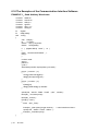
6.16 The Examples of the Communication Interface Software
EXAMPLE 1:Send Arbitrary Waveforms
#include
#include
#include
#include
#include
#include
<stdlib.h>
<userint.h>
<utility.h>
<gpib.h>
<ansi_c.h>
<string.h>
int
int
sfg830
data[10000];
void
{
main( )
char cmd[10];
int
i,j,number;
double amp,cycle,phase;
double wave[10000];
if ( (sfg830=ibfind(〝dev8〞) <0 )
{
printf (〝cannot find SFG830\n〞);
exit(1);
}
number=1000;
amp=2;
phase=0;
cycle=1;
SinePattern(number,amp/2,phase,cycle,wave);
for(j=0;j<munber;j++)
{
wave[j]=4094∗wave[j]/amp;
data[j]=(short)(wave[j]+0.5);
}
for(j=0;j<number;j++)
{
if(data[j]<0)
data[j]=(0xffff-data[j]+1)+0x8000;
}
sprintf(cmd,〝SOUR:FUNC:LDWF %d\n〞,number);
ibwrt(dev_, cmd,strlen(cmd));
ibwrt(dev_,cmd,40);
if(cmd[1]= =0x31)
{
ibtmo (dev_,T30s);
ibwrt(dev_,(char∗)data,(1ong)2∗number); /∗ send waveforms data ∗/
sprintf(cmd,〝SOUR:FUNC:ARB\n〞);
ibwrt(dev_,cmd,strlen(cmd));
}
}
p. 24
SFG-830
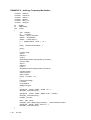
EXAMPLE 2:Arbitrary Amplitude Modulation
#include
#include
#include
#include
#include
#include
<stdlib.h>
<userint.h>
<utility.h>
<gpib.h>
<ansi_c.h>
<string.h>
int
int
sfg830
data[10000];
void
{
main( )
char cmd[40];
int
i,j,number;
double amp,cycle,phase;
double wave[10000];
if ( (sfg830=ibfind(〝dev8〞) <0 )
{
printf (〝cannot find SFG830\n〞);
exit(1);
}
number=1000;
amp=2;
phase=0;
cycle=1;
SinePattern(number,amp/2,phase,cycle,wave);
for(j=0;j<number;j++)
{
wave[j]=2048+(1368∗wave[j])
data[j]=(int) (wave[j]+0.5);
}
sprintf(cmd,〝SOUR:FUNC:SOUR 5\n〞);
ibwrt(dev_,cmd,strlen(cmd));
sprintf(cmd,〝SOUR:FUNC:AMOD %d\n〞,number);
ibwrt(dev_,cmd,strlen(cmd));
ibrd(dev_,cmd,40);
ibtmo (dev_, T30s);
ibwrt(dev_,(char ∗)data,(1ong)2∗number); /∗ send waveforms data ∗/
sprintf(cmd,〝SOUR:MOD:STAT 1\n〞);
ibwrt(dev_,cmd,strlen(cmd));
}
SFG-830
p.25
EXAMPLE 3:Arbitrary Frequency Modulation
#include
#include
#include
#include
#include
#include
<stdlib.h>
<userint.h>
<utility.h>
<gpib.h>
<ansi_c.h>
<string.h>
int
int
sfg830
data[10000];
void
{
main( )
char cmd[40];
int
i,j,number;
double amp,cycle,phase;
double wave[10000];
double t,center,span,s;
if ( (sfg830=ibfind(〝dev8〞) <0 )
{
printf (〝cannot find SFG830\n〞);
exit(1);
}
number=1000;
amp=2;
phase=0;
cycle=1;
SinePattern(number,amp/2,phase,cycle,wave);
number=1000;
amp=2;
phase=0;
cycle=1;
sinepattern(number,amp/2,phase,cycle,wave);
s=pow(2.0,32.0);
center=10.0E3;
span=10.0E3;
for(i=0;i<number;i++)
{
t=span/2.0∗wave[i];
t+=center;
t/=42.9496E6;
data[i]=(1ong)s∗t;
}
sprintf(cmd,〝SOUR:FUNC:SOUR 5\n〞);
ibwrt(dev_,cmd,strlen(cmd));
sprintf(cmd,〝SOUR:FUNC:AMOD %d\n〞,number);
ibwrt(dev_,cmd,strlen(cmd));
ibrd(dev_,cmd,40);
ibtmo (dev_,T30s);
ibwrt(dev_,(char ∗)data,(long)4∗number); /∗send waveforms data ∗/
sprintf(cmd,〝SOUR:MOD:STAT 1\n〞);
ibwrt(dev_,cmd,strlen(cmd));
}
p. 26
SFG-830
7. Adjustment and Correction
7.1 Preparation
n Preheat the instrument for more than 30 minutes.
o The operation temperature should be 23±5oC, and the humidity should be
lower than PH80%.
p The voltage should be (a) ±15V±0.90V or (b) ±5V±0.25V.
q If the voltage is correct, then plug in Q2334, Q2520 and AD834.
r Press [ Shift ] [ 9 ] [ 8 ] [ 3 ] [ 0 ], then all the calibration values will be cleared.
7.2 Adjusting Clock
n Set Conditions:
Function : Sine Wave
Amplitude : 5Vp-p
Modulation : OFF
Frequency : 10MHz
o Use Counter to measure the output.
p Adjust X202 until the frequency reaches the range of 10MHz±20Hz.
7.3 Adjusting the DC of Frequency Double
n Set Conditions:
Function : Sine Wave
Amplitude : 10Vp-p
Frequency : 10kHz
o Use an oscilloscope at AC 100mV/DIV, 20us/DIV to measure U303 - Pin 1.
p Adjust SVR301 until a flat DC signal shows up.
7.4 Adjusting D/A Ref
n Set Conditions:
Function : Sine Wave
Amplitude : 10Vp-p
Modulation : OFF
Frequency : 1kHz
o Use an oscilloscope with 50 ohm load to measure the output.
p Adjust SVR201 until the output becomes symmetric sine waves.
7.5 Adjusting the Bandwidth
n Set conditions:
Function : Square Wave Amplitude : 8Vp-p
Modulation : OFF
Frequency : 10kHz
o Use DMM at DCV range to measure U601-Pin6, and adjust SVR601 until the
readout to be 0.0V.
p Set conditions :
Frequency : 100Hz
q Use an oscilloscope at 2V/DIV, 5ms/DIV, with 50 ohm load to measure the
output. Then adjust SVR604 until the output becomes flat square waves.
r Set condition :
Frequency : 500kHz
s Use an oscilloscope at 2V/DIV, 1us/DIV, with 50 ohm load to measure the
output. Then adjust SVR602 until the output becomes flat square waves.
t Set condition :
Frequency : 500kHz
u Use an oscilloscope at 2V/DIV, 200ns/DIV with 50 ohm load to measure the
output. Then adjust SVC601 to get the shortest rise time and the overshoot be
<5%.
SFG-830
p.27
7.6 Adjusting the Filter
n Press [Shift] + [DEFAU] keys
o Set conditions:
Function : ARB
Amplitude : 8Vp-p
Frequency : 2MHz (sampling frequency)
p Use a oscilloscope at 2V/DIV, 200ns/DIV with 50 ohm load to measure the
output.
q Adjust SVC301, 302, 303, and 304 in turn to get the shortest rise time and the
smallest peak to peak ripple.
r Repeat steps n~q once.
7.7 Adjusting Harmonic Distortion
n Set conditions:
Function : Sine Wave
Amplitude : 8Vp-p
Frequency : 15kHz
o Use a spectrum analyzer with 50 ohm load, start frequency at 0Hz and stop
frequency at 15kHz, to measure the output.
p Adjust SVR501 until get the smallest second harmonic (20kHz).
q Repeat step n and o.
r Adjust SVR603 until third harmonic (45kHz) and fifth harmonic (75kHz)
achieve the same level.
NOTE : When use software in calibrating , these steps should be gone through after Callier Null
calibration. Meanwhile, adjust SVR501 and SVR603 to minimize distortion.
7.8 Calibrating by Software
(A) Calling Default Calibration Data
n Press [Shift], [9], [8],[3], [0] keys.
ª The display will indicate “default” for a few seconds, then shows 1000.00Hz.
The calling of default calibration data is then finished.
(B) Manual Calibration
Basic Steps :
n Press [Shift], [0], [8], [3], [0] keys to shift to the manual calibration mode.
ª The display will indicate “CAL EDIT” for a few seconds, then shows 00001
(blinking) and 1000. The figures on the left side represent the Calibration
Number, and the right-hand figures are the corresponding Calibration Value.
The blinking area is where you can input figures, and can be switched by
pressing the [ ] and [ ] keys in FUNCTION column.
p. 28
SFG-830
o Use [▲] and [▼] keys in MODIFY column or press numeric keys [0]~[9] to input
the desired value.
Example:
i.) If the display shows “00001 1000” and 00001 blinks, it means that the
Calibration Number is ready for input. Press FUNCTION [ ] key once, then
1000 becomes blinking and you can input the Calibration Value. Press
FUNCTION [ ] key once, then 00001 will blink again.
ii.) Press [4], [0], [6] and [Enter] keys will get to the Square Wave Symmetry
Calibration mode, and the Calibration Value is 2000. Press FUNCTION [ ] key
once, and 2000 will be blinking. Just input the desired figures, then the
symmetry of square wave will be changed.
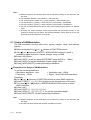
The table below lists the corresponding Calibration Numbers to Calibration items:
Calibration Item
Calibration Number
Positive Attenuator Calibration
Negative Attenuator Calibration
Carrier Null Calibration
Amplitude of Sine Wave
Amplitude of Square Wave
Amplitude of Triangle Wave
Symmetry of Square Wave
Sine DC Gain Calibration
Square DC Gain Calibration
Triangle DC Gain Calibration
Offset Adjustment
1~8
9 ~ 16
17 ~ 113
114 ~ 307
308 ~ 404
405
406 ~ 502
503
504
505
506 ~ 602
Calibration Mode
Manual Calibration
Auto Calibration
The procedure of manual calibrating with software is as follows:
(1) Positive Attenuator Calibration
To calibrate the positive attenuator, you should go through Calibration Number 1 ~
8 in turn, and perform the following 3 steps for each number.
n Set the Calibration Number.
o Use a DMM (FLUKE-8842) at DCV range to measure the output.
p Key in an appropriate Calibration Value to make the output to be the particular
value listed below:
p Output should be :
n Calibration Number
1
2
3
4
5
6
7
8
o Use a DMM (FLUKE-8842) at
DCV range to measure the
output
39
78
156
312
625
1.25V
2.5V
5V
±
±
±
±
±
±
±
±
0.1mV
0.5mV
1mV
1mV
2mV
10mV
10mV
10mV
SFG-830
p.29
(2) Negative Attenuator Calibration
To calibrate the negative attenuator, you should go through Calibration Number 9
~ 16 in turn, and perform the following 3 steps for each number.
n Set the Calibration Number.
o Use a DMM (FLUKE-8842) at DCV range to measure the output.
p Key in an appropriate Calibration Value to make the output to be the particular
value listed below:
n Calibration Number
9
10
11
12
13
14
15
16
p Output should be :
o Use a DMM (FLUKE-8842) at
DCV range to measure the
output
-39
-78
-156
-312
-625
-1.25V
-2.5V
-5V
±
±
±
±
±
±
±
±
0.1mV
0.5mV
1mV
1mV
2mV
10mV
10mV
10mV
(3) Carrier Null Calibration
n Set the Calibration Number to 17.
o Use a distortion meter (DM-155 A/B) to measure the output.
p Key in an appropriate calibration value to minimize the distortion. Then go
through stepq~t repeatedly to calibrate the output of Number 18 ~ 113.
q Set the Calibration Number (18 ~ 113, one number each time).
r Use a spectrum analyzer to measure the output.
s Set the Center Frequency of the spectrum analyzer to be X, where
X = ( Calibration Number − 17 )× 312500 + 1000 .
t Key in an appropriate Calibration Value to minimize the power of frequency Y,
where Y =
X
.
2
(4) Calibrating the Amplitude of Sine Wave
n Set the Calibration Number 114 ~ 115 (one number each time).
o Use a DMM (FLUKE-8842) at ACV range with 50 ohm load to measure the
output.
p Input an appropriate Calibration Value until the output to be the corresponding
figures as listed in the table below. Then go through stepq~s repeatedly to
calibrate the output of Number 116~307.
q Set the Calibration Number 116 ~ 307 (one number each time).
r se a measuring receiver (HP-8902A or equivalent for high frequency amplitude
checks) at ACV range to measure the output.
s Input an appropriate Calibration Value to make the output to be as follows:
p. 30
Calibration Number 114~307
Output Voltage
odd
1.77 ± 0.005Vrms
even
3.54 ± 0.01Vrms
SFG-830
(5) Calibrating the Amplitude of Square Wave
Go through stepn~p repeatedly to calibrate the output of Number 308 ~ 404.
n Set the Calibration Number.
o Use an oscilloscope with 50 ohm load to measure the output.
p Input an appropriate Calibration Value to make the output to be 10±1Vp-p.
(6) Calibrating the Amplitude of Triangle Wave
n Set the Calibration Number to be 405.
o Use an oscilloscope at 50Ω to measure the output.
p Input an appropriate Calibration Value to make the output to be 10±1Vp-p.
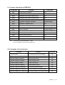
(7) Calibrating the Symmetry of Square Wave
Go through stepn~p repeatedly to calibrate the output of Number 406 ~ 502.
n Set the Calibration Number.
o Use a fixture with 50Ω to measure the output.
s Input an appropriate Calibration Value to make the output to be as follows:
Calibration Number
Duty
406 ~ 437
50% ± 1% + 4ns
438 ~ 460
48%
461 ~ 486
45%
487 ~ 502
40%
(8) Finishing Manual Calibration
n Press [ STOR ] key.
ª “Default” will be shown on the display after 3 seconds.
(C) Automatic Calibration
n Press [Shift], [1], [8], [3], [0] keys to shift to automatic calibration mode.
ª In a few minutes “Auto Cal” will be shown on the display, indicates the
accomplishment of automatic calibration.
The table below lists the corresponding items to the Calibration Numbers:
Calibration Item
Sine DC Gain
Square DC Gain
Triangle DC Gain
Adjusting DOB_U
Calibration Number
503
504
505
506 ~ 602
All of the calibrating procedure is accomplished after the automatic calibration.
SFG-830
p.31
7.9 Checking Frequency Accuracy
The deviation should be within ±5ppm.
n Set conditions:
Function : Sine Wave
Amplitude : 1Vp-p
Frequency : 10MHz
o Use a counter with 50 ohm load to measure the output.
p Check and make sure the output is 10MHz ± 40Hz.
7.10 Checking the Amplitude
(1) Check the Amplitude of Sine Wave
The deviation should be ±0.5dB (±5.9%).
n Set conditions:
Function : Sine Wave
Amplitude : 3.54Vrms (10Vp-p)
Frequency : 100Hz
o Use a DMM (FLUKE-8842) at ACV range with 50 ohm load to measure the
output.
p Check and make sure that 3.33Vrms < output < 3.74Vrms.
q Keep the same Function and Amplitude, and set Frequency to be 1kHz, 10kHz,
100kHz, 1MHz, and 2 ~ 30MHz (step 2MHz) in turn.
r Perform step o~q (use measuring receiver HP-8902 or equivalent needed for
HF Amplitude check instead) in each frequency setting until the Frequency =
30MHz.
s Set conditions:
Function : Sine Wave
Amplitude : 1Vrms
Frequency : 100Hz
t Use a DMM (FLUKE-8842) at ACV range with 50 ohm load to measure the
output.
u Check and make sure that 0.94Vrms < output < 1.04Vrms.
v Keep the same Function and Amplitude, and set Frequency to be 1kHz, 10kHz,
100kHz, 1MHz, and 2 ~ 30MHz (step 2MHz) in turn.
w Perform step t~v (use measuring receiver HP-8902 or equivalent needed for
HF Amplitude check instead) in each frequency setting until the Frequency =
30MHz.
(2) Checking the Amplitude of Square Wave
The deviation should be ±12%.
n Set conditions:
Function : Square Wave
Amplitude : 10Vp-p
Frequency : 100Hz
o Use an oscilloscope with 50 ohm load to measure the output.
p Check and make sure that 8.8Vp-p < output < 11.2Vp-p.
q Keep the same Function and Amplitude, and set Frequency to be 1kHz, 10kHz,
100kHz, 1MHz, and 2 ~ 30MHz (step 2MHz) in turn.
r Perform step p~q in each frequency setting until the Frequency = 30MHz.
p. 32
SFG-830
(3) Checking the Amplitude of Triangle Wave
The deviation should be ±5%.
n Set conditions:
Function : Triangle Wave
Amplitude : 10Vp-p
Frequency : 100Hz
o Use an oscilloscope with 50 ohm load to measure the output.
p Check and make sure that 9.5Vp-p < output < 10.5Vp-p.
q Keep the same Function and Amplitude, and set Frequency to be 1kHz, 10kHz,
and 100kHz in turn.
r Perform step p~q in each frequency setting until the Frequency = 100kHz.
(4) Check the Accuracy of DC Offset
The deviation should be ±1.5% + 1mV.
n Set conditions:
Function : Sine Wave
Amplitude : 0.0Vp-p
Frequency : 1kHz
DC Offset : 5V, -5V, 0V in turn
o Use a DMM at DCV range with 50 ohm load to measure the output.
p Check and make sure the corresponding output to each DC Offset is in the
range listed below:
DC Offset
5V
-5V
0V
Output
4.925V ≤ output ≤ 5.075V
-5.075V ≤ output≤ -4.925V
-1mV ≤ output ≤ +1mV.
(5) Checking the Sub Harmonic
The deviation should be <-50dBC.
n Set conditions:
Function : Sine Wave
Amplitude : 10Vp-p
DC Offset : 0V
o Use a spectrum analyzer to measure the output.
p Check and make sure that the corresponding output to each Frequency setting
is in the range listed below:
Frequency
102kHz
1.001MHz
10.001MHz
20.001mHz
30.0mHz
Center Frequency of
Spectrum Analyzer
51kHz
501kHz
5.001MHz
10.001MHz
15.0mHz
Harmonic
< -26.02dBm
SFG-830
p.33
(6) Checking the Harmonic Distortion
The deviation should be :
Deviation
< -50dBC
< -40dBC
< -30dBC
< -25dBC
Frequency
< 100kHz
0.1 ~ 1MHz
1 ~ 10MHz
10 ~ 30MHz
n Set conditions:
Function : Sine Wave
Amplitude : 1Vp-p
Frequency : 100Hz
o Use a distortion meter (DM-155A/B) with 50 ohm load to measure the output.
p Check and make sure that the output should be < -50dBC (0.31%).
q Set the Frequency to be 1kHz, 10kHz, 50kHz, and 100kHz in turn.
r Perform step p and q until the Frequency = 100kHz.
s Use a spectrum analyzer to measure the output.
t Check and make sure that the corresponding output to each Frequency setting
is in the range listed below:
Frequency
500kHz
5MHz
15MHz
30MHz
Output
< -40dBC
< -30dBC
< -25dBC
< -25dBC
(7) Checking the Phase Noise
The deviation should be <-50dBC.
n Set conditions:
Function : Sine Wave
Amplitude : 13dBm
Frequency : 10MHz
o Use a spectrum analyzer to measure the output.
p Check and make sure that the difference between the powers of 10MHz and
10MHz+15kHz is less than 50dBC.
(8) Checking the Rise Time of Squire Wave
The deviation should be : Rise Time < 15ns and Overshoot < 5% at full scale
output.
n Set conditions:
Function : Square Wave
Amplitude : 10Vp-p
Frequency : 1MHz
o Use an oscilloscope with 50 ohm load to measure the output.
p Check and make sure that the Rise Time < 15ns and
the Overshoot / Undershoot < 500mVp-p.
p. 34
SFG-830
(9) Checking the Symmetry of Square Wave
The deviation should be < ±1% of period +4ns.
n Set conditions:
Function : Square Wave
Amplitude : 10Vp-p
Frequency : 1MHz
o Use an oscilloscope with 50 ohm load to measure the output.
p Check and make sure that the output is 49:51 or 51:49.
(10) Checking the AM Envelop Distortion
The deviation should be < -35dB at 1kHz.
n Use a spectrum analyzer, with Center Frequency at 1MHz and Span
Frequency at 20kHz, to measure the output.
o Check and make sure that the differences between powers of Basic Wave and
sidebands (2k, 3k, …, Offset) are less than 35dB.
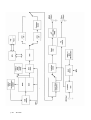
8. The Block Diagram and Description of the System
Graph 2 is the block diagram of SFG-830 system, which consists of a micro
processor unit (MPU), a direct digital synthesizer (DDS), a digital to analog converter
(DAC), a RAM module, a low pass filter (LPF), a frequency double (F.D.), a square
waveform comparator, a amplitude control, an output amplitude, an attenuator (ATT),
etc. The principles of generating waveforms are stayed as follows:
(1) Sine Waveform
The data of waveform is stored in the lookout table of DDS (Q-2334). The output
frequency can be altered by solely changing the control word K (please refer to
Chapter 2). The digital output passes the DAC and be converted to a step-shape
analog signal. This signal will then be filtered by a 9-level LPF2, and becomes a
pure sine wave. Due to the frequency response of DDS and the points of the
output waveform, the sine wave should pass the F.D. circuit (U301 and AD834),
the amplitude control, the output amplitude, ATT, and output through the Main Out
terminal.
(2) Square Waveform
The procedure of generating square waveforms is similar to that of generating sine
waveforms. The only difference is that the signal will pass a square wave
comparator circuit between the F.D. circuit and the amplitude control.
SFG-830
p.35
p. 36
SFG-830
(3) Triangle Waveform
When the user input a frequency, the MPU will calculate the correspondent data
then save it in RAM(II) (U211-U213), and save the number of the data in the
Up/Down Counter (U215-U218) 74F193. As the Up/Down counter is controlled
by the B11 in DDS1 through 74F193 CLK Input, the desired frequency value can
be obtained by changing the counter’s reading frequency, i.e., the frequency of
CLK. The output frequency of triangle waveform is lower that that of sine waveform
and square waveform due to the different paths. The triangle wave passes a 7level LPF1 and does not go through F.D.
(4) Ramp
The procedure of generating ramp is the same as that of generating triangle
waveforms.
(5) AM Modulation
This includes internal modulation and external modulation with the same operation
procedure. Take internal modulation for example, the input data will be calculated
by MPU and be written in RAM(III) (8k×8); the Up/Down Counter will then read out
the data in RAM and send it to the Amplitude Control (U501, AD834) via DAC.
Different input voltages can change the output voltages of Amplitude Control, thus
achieve the modulation effect.
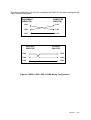
(6) Sweep
(a) Sine wave and Square wave:
As to the sine wave sweep, the input data will be calculated by MPU and be
written in RAM(I) (8k×8); DDS2 will then send a fixed frequency to read the
sweep data from RAM(I), and send it to DDS1 through the Bus Selector. The
digital sine wave signal generated from DDS1 will pass DAC, 9-level LPF, F.D.,
Amplitude Control, Output Amplitude, ATT, then output via DUT.
The procedure of square wave sweep is similar to the above one, except that
the digital signal generated from DDS1 passes a Square Waveform
Comparator between the F.D. and Amplitude Control.
(b) Triangle wave and Ramp:
The input data will be calculated by MPU and be written in RAM(II); DDS1 will
then send a B11 control frequency to read the sweep data from RAM(II).
Afterwards, the signal will pass the Bus Selector, DAC, 7-level LPF, Amplitude
Control, Output Amplitude, ATT, then output via OUT BNC.
(7) FM Modulation
The principle of FM modulation is the same as that of Sweep, except that the data
stored in RAM (I) is relevant to FM modulation.
SFG-830
p.37
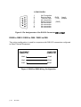
Appendix 1
*IDN?
Commands of IEEE488.2
Identification Query
z After receipt of this query the instrument generates response
message as below:
z The response consists of the following four fields:
─Manufacture
─Model
─Serial Number (return 0 if not available)
─firmware Revision (return 0 if not available)
z The fields are separated by commas.
z Example:GW.Inc,SFG-830,Serial number 1111-000-90,1.0.
*RST
Reset Command
z The command performs a device reset which sets the instrument to a
defined status as bellow:
modulation
waveform
DC-offset
OFF
sine
OV
frequency
amplitude
1KHz
1V
z The reset command shall not affect the following:
─The state of the IEEE 488.1 interface
─The selected IEEE 488.1 address of the device
─The Output Queue
─The Service Request Enable Register.
─The Standard Event Status Enable Register
─Calibration dat
p. 38
SFG-830
*TST?
Selftest Query
z Cause an instrument to execute an internal self-test and returns a
response showing the results of the self-test.
z A zero response indicates that self-test passed.
z A value other than zero indicates a self-test failure or error.
z The response syntax for the self-test query id defined as bellow:
0
1
2
3
4
5
Self-test has completed without errors detected.
CPU Error. The device has detected a problem in its
CPU.
Sys RAM Error. The system RAM failed its test.
Code Error. The device ROM firmware has a
checksum error.
8279 Error
A/D or D/A Error
*WAI
Wait-to-Continue Command
z Prevents an instrument from executing another command until the
operation caused by previous command is finished (sequential
operation).
*OPC
Operation Complete Command
z Sets bit 0 (Operation Complete Message) in the Standard Event
Register when all pending instrument operations are finished.
SFG-830
p.39
*OPC?
Operation Complete Query
z Place an ASCII character 1 into the instrument‘s output queue when
all pending instrument operations are finished.
*CLS
Clear Status Command
z This command clears status data structures. On the other hand, it
sets the bits of the〝Standard Event Register〞and the〝Status Byte
Register〞to zero.
z The Output Queue and the MAV bit will not be cleared.
*ESE
Standard Event Status Enable Command
z *ESE, followed by a decimal value, sets the bits of the〝Standard
Event Status Enable Register〞which correspond to that decimal value
to 1. This enables the assigned bits of the〝Standard Event Status
Register〞.
*ESE?
Standard Event Status Enable Query
z This query asks for the contents of the 〝Standard Event Status Event
Register〞.The response is a decimal value, e.g.,〝255〞means all
events of the〝Standard Event Status Register〞are enabled, in other
word, all bits are 1.
*ESR?
Standard Event Status Register Query
z Ask for the contents of the〝Standard Event Status Register〞. The
response is a decimal value. The query clears the register contents.
p. 40
SFG-830
*SRE
Service Request Enable Command
z *ESE, followed by a decimal value, sets the bits of the〝Service
Request Enable Register〞which correspond to that decimal value to
1, except bit 6. For all bits except bit 6, a bit value of one shall indicate
an enabled condition. The bit value of one indicates a disabled
condition. The bit value of bit 6 shall be ignored.
*SRE?
Service Request Enable Query
z Asks for the contents of the〝Service Request Enable Register〞.
The response is a decimal value.
*STB?
Read Status Byte Query
z Asks for the contents of the〝Status Byte Register〞. The response is
a decimal value.
*SAV
Save Command
z This command followed by a decimal value stores the current
instrument setting into the corresponding memory place. The
contents of the memory is not affected by the command *RST or
when POWER OFF the instrument.
*RCL
Recall Command
z This command followed by a decimal value for the memory place call
up and executes the instruments settings stored in that memory
place.
SFG-830
p.41
STATUS BYTE DEFINTIONS:
0
1
2
3
4
5
6
7
STB
Serial Poll Status Byte
Sweep Done
set when no sweeps are in progress
Mod Enable
set when modulation is enabled
not used
not used
MAV
The GPIB output queue is non-empty.
ESB
An unmasked bit in the ESE byte has been set.
RQS/MSS
SRQ (Service Request) bit.
ERRBIT
The GPIB command has error occurred.
ESR
0
1
2
3
4
5
6
7
p. 42
OPCOL
RSQCTL
QUEERR
DDERR
EXUERR
CMDERR
URSQ
PON
SFG-830
Standard Event Status Byte
Operation complete.
Request control.
Query error.
Device dependent error.
Execution error.
Command error.
User request.
Set by power on.
APPENDIX 2: RS-232 Wiring Configuration
SFG-830 is a DTE device with a 9-pin D-type male or 25-pin D-type female shell RS232 connector located on the rear panel. In standard usage, a male connector
appears on DTE devices, and a female connector appears on DCE devices. A
straight through female-to-male cable of less than 50 feet is typically used for local
DTE-to-DCE connection. When connecting the equipment to another RS-232
device consider the suggestions as follows:
z
z
z
z
Many devices require a constant high signal on one or more input pins.
Do not connect the output line of one DTE device to the output line of the other.
Ensure that the signal ground of the equipment is connected to the signal ground
of the external device.
Ensure that the chassis ground of the equipment is connected to the chassis
ground of the external device.
25-PIN D-SHELL
1.
2.
3.
4.
5.
6.
7.
8.
9.
10.
11.
12.
13.
14.
15.
16.
17.
18.
19.
20.
21.
22.
23.
24.
25.
No Connection
Receive Data (R×D)
Transmit Data(T×D)
No Connection
No Connection
No Connection
Signal Ground
No Connection
No Connection
No Connection
No Connection
No Connection
No Connection
No Connection
No Connection
No Connection
No Connection
No Connection
No Connection
No Connection
No Connection
No Connection
No Connection
No Connection
No Connection
(input)
(output)
(GND)
Figure 1: Pin Assignments of the RS-232 Connector(DB-25-D Female)
SFG-830
p.43
9-PIN D-SHELL
1.
2.
3.
4.
5.
6.
7.
8.
9.
No Connection
Receive Data
Transmit Data
No connection
Signal Ground
No connection
No connection
No connection
No connection
(R×D)
(T×D)
(input)
(output)
(GND)
Figure 2: Pin Assignments of the RS-232 Connector(DB-9-D Male)
DB25 to DB25 / DB25 to DB9 / DB25 to DB9
This wiring configuration is used for computers with DB-25-D connectors configured
as Data Terminal Equipment.
EQUIPMENT
(DB25,DTE)
COMPUTER
(DB25,DTE)
Pin2
Pin2
Pin3
Pin3
Pin7
Pin7
Figure 3: DB25 to DB25 Wiring Configuration
p. 44
SFG-830
This wiring configuration is used for computers with DB-9-D connectors configured as
Data Terminal Equipment.
EQUIPMENT
(DB25,DTE)
COMPUTER
(DB9,DTE)
Pin2
Pin2
Pin3
Pin3
Pin7
Pin5
Equipment
(DB9, DTE)
Computer
(DB9, DTE)
Pin2
Pin2
Pin3
Pin3
Pin5
Pin5
Figure 4: DB25 to DB9 / DB9 to DB9 Wiring Configuration
SFG-830
p.45