1
User Manual
SHAPE 3D X
User Manual
Version 9.00
1
User Manual
Quick Start ........................................................................................................... 5
The General Modes ............................................................................................ 5
Designing a Board from Scratch ......................................................................... 9
Designing a Board from Measurements ............................................................ 13
Designing a Blank ............................................................................................. 18
The Design Mode ............................................................................................... 20
The “New board design” Window ...................................................................... 20
The “General Design” Tab .............................................................................. 20
The “Blank Design” Tab .................................................................................. 22
The “Size and parameters” Window .................................................................. 22
The “Name and size” Tab ............................................................................... 22
The “File Protection” Tab ................................................................................ 23
The “Fins boxes” Tab ...................................................................................... 24
The “Master Scale” Window .............................................................................. 27
The “Control point” Window .............................................................................. 29
The “Curves List” Window ................................................................................. 30
The “Slices List” Window ................................................................................... 32
The Multi-Curves Edition ................................................................................... 33
The 3D Layers................................................................................................... 36
The Tool Bar ..................................................................................................... 42
The Menu Bar ................................................................................................... 48
File .................................................................................................................. 48
Board .............................................................................................................. 51
Mode ............................................................................................................... 52
View ................................................................................................................ 52
Components ................................................................................................... 52
Control points .......................................................................................................... 53
Slices ........................................................................................................................ 53
3D Layers ................................................................................................................. 54
Fins ........................................................................................................................... 54
Guidelines ................................................................................................................ 55
Measurement Bars ................................................................................................. 55
Buoyancy Line ......................................................................................................... 56
Automatic Fitting ..................................................................................................... 56
Display ............................................................................................................ 57
Superpose ...................................................................................................... 58
Ghost Board............................................................................................................. 59
Image ........................................................................................................................ 60
Windows ......................................................................................................... 61
Help (?) ........................................................................................................... 62
The Right Click: The Context Menu .................................................................. 66
The Shortcuts .................................................................................................... 67
Avoiding Design Mistakes ................................................................................. 69
Width and Thickness ...................................................................................... 69
Exceeding the Board Length........................................................................... 70
2
User Manual
Smoothness and Continuity ............................................................................ 70
Slices .............................................................................................................. 71
Apex and Rail Definition ................................................................................. 72
The 3D Mode ...................................................................................................... 73
The Tool Bar ..................................................................................................... 73
The Menu .......................................................................................................... 79
The Plan Mode ................................................................................................... 80
The Tool Bar ..................................................................................................... 80
The Menu .......................................................................................................... 82
Plans ............................................................................................................... 82
Marks .............................................................................................................. 82
Full Scale ........................................................................................................ 84
The CNC Mode ................................................................................................... 86
The Machine File............................................................................................... 86
The Properties Box ........................................................................................... 87
The “CNC Settings” Tab ................................................................................. 88
The “Blank Position” Tab ................................................................................ 90
The “Tool Path” Tab ........................................................................................ 96
Path ........................................................................................................................... 96
Stringer paths .......................................................................................................... 98
Outline cut ................................................................................................................ 99
The “Tool Path 2” Tab ................................................................................... 100
Starting/End position ............................................................................................ 101
Stringer ends ........................................................................................................... 98
Margins ................................................................................................................... 101
Fins plugs ............................................................................................................... 101
Rods ........................................................................................................................ 102
Relief cuts .............................................................................................................. 102
The “3D Layers” Tab ..................................................................................... 103
The “Cutter” Tab ........................................................................................... 105
Bull Nose ................................................................................................................ 105
Bull Nose for 4-5 Axis........................................................................................... 105
Disk ......................................................................................................................... 106
Symmetric Bull Nose ............................................................................................ 107
Multi Bull Nose ...................................................................................................... 107
The “Axis” Tab .............................................................................................. 107
The Tool Bar ................................................................................................... 108
The Scan Option .............................................................................................. 113
The Data Type BOARD: One Text, G-Code or DXF Data File ........................ 113
If everything looks alright: ............................................................................. 114
If the scan data doesn't look good: ............................................................... 114
If the automatic adjustment fails: .................................................................. 116
When the automatic fitting is finished: .......................................................... 116
Data Type Brd 2files: Two Text, G-Code or DXF Data File ............................. 117
The 3DM Scan Function ................................................................................. 118
3
User Manual
The KKL Scan Function .................................................................................. 118
The Data Types Outline, Bottom, Deck, Thickness, and Slice ........................ 119
The Export Option ........................................................................................... 122
Contact ............................................................................................................. 124
4
User Manual
Quick Start
The General Modes
Shape3d presents four edition modes that can be selected in the general toolbar:
The Design Mode presents three 2D views of the boards that can be the outline, the profile,
the thickness or the slices. In each view, the curves can be modified through the control points. The
measures of the board are shown in the Master Scale box.
The 3D Mode allows the visualization of the boards as a 3D object, either with a solid
rendering or a wired rendering.
5
User Manual
The Plan Mode displays board charts with measurements, and full scale printable view of the
board.
The CNC Mode presents all the settings of the CNC machine, and allows to compute, and
visualize the cutting path.
6
User Manual
The general toolbar, which is accessible in each edition mode, also contains some general functions:
This button opens a dialog box that allows creating a new board from an existing model or from
measurements.
This button allows to open an existing model.
Save the current model.
Open the “Size & Parameters” dialog box that allows to change the dimensions of the board, as well
as other properties that will be presented farther down.
Select the measurements unit.
7
User Manual
8
User Manual
Designing a Board from Scratch
Go to the menu "File", then "New", or press the button “New”
. The following window pops up.
- Choose the model to start from between the examples proposed in C:\Shape3dmodels.
- Enter the name of the model you are going to design, and your name as a shaper. Add any comments you
want.
- Choose the dimensions unit: centimeters, millimeters, inches or fractional inches.
- Check the box “symmetric nose/tail” for a twin-tip board.
- Input length, width, thickness, and tail/nose rocker.
- Check the box “Stringer measurement” if these dimensions are measured along the stringer. Uncheck it if
9
User Manual
they are measured along a straight line.
- Press OK.
The starting model appears in the Design mode.
You can visualize three components of the board at the same time, choosing between Outline, Profile,
Thickness, or Slices in the toolbar.
The dimensions of the board appear in the Master Scale box.
To modify the design of the curves, left click on the control points. The selected control point becomes red.
You can move the control points with the mouse, or with the arrows of the keyboard.
You can delete a control point pressing the button “Suppr” of the keyboard, or with a right click, selecting
“Control point”, “Delete”.
You can also add a control point with a double left click at the position you want, or with a right click,
selecting “Control point”, “Add new point”.
10
User Manual
The properties of the selected control point are shown in the “Control point properties” box.
Five kind of tangents exist: continuous tangents
horizontal tangents
, angular tangents
, and continuous tangents with fixed angle
, vertical tangents
,
.
Continuous tangents are usually used. The angular tangents are more appropriate for the rail point of the
slices, the vertical tangents for the apex of the slices, and the horizontal ones for the widest point of the
outline, the zero point of the bottom, or the highest point of the thickness.
When designing the slices, it is recommended to set the point type of the rail point as
point as
, and the apex
. They will then appear in bleu and green respectively.
All the slices must have the same number of control points.
11
User Manual
The position of the slices can be modified with a right click, selecting “Slices”, “Move slice”. It can also be
changed with the mouse in the outline view.
You can add or delete a slice, in the same way.
You can visualize the “flow” of the slices maintaining a left click in the outline, profile or thickness view. The
width, rocker or thickness appear at the same time, as well as the distance from the tail and from the nose.
12
User Manual
To understand the idea behind the design of a board with shape3d, just think about the rule of thumb: the
less points the smoothest. Similarly, the less slices the smoothest.
Visualize the result of your art in the 3D View mode.
Designing a Board from Measurements
As if you would design a board from scratch, go to the menu « File », then « New », or press the button
“New”
, and fill in the name and size areas.
Then press the button “Measurement wizard”. The measurement wizard window pops up. You can choose
to measure the dimensions of the board along the stringer:
13
User Manual
or along a straight line, checking the box “Straight line measurements”:
or along a straight line, checking the box “Straight line measurements”:
14
User Manual
Click on the button more if you want to place the guidelines at other positions than the default ones:
The positions of the guidelines along the length direction depend on the chosen unit: in centimeters, the
guidelines are located at 5, 10, 20, 30 cm… from the tail and the nose. In inches, the guidelines are
located at 1”, 3”, 6”, 12”… from the tail and the nose.
You don’t need to fill in each position box.
The outline and the profile will be automatically adjusted on the guidelines if you check the box “Automatic
fitting”.
15
User Manual
Press “OK” to see the board in the Design mode.
The guidelines appear as green crosses. Their list, with the positions, appears on the right hand side of the
bottom of the screen.
You can change their position with the mouse, or the keyboard, or with a right click in the “Guidelines” box,
which will make the following window appear.
After changing the position of the guidelines, you can automatically fit the curves on the guidelines doing a
right click on the selected curve.
16
User Manual
If you click on a curve section between two control points, you have the possibility to adjust only this
selected part of the curve, choosing “Fit selected curve to the guidelines”.
Then you have to choose if you want to adjust the length or the direction of each tangent, or both. And
press OK.
You can also choose to adjust the whole curve, clicking on “Fit the whole curve to the guidelines”.
In this case you can choose the number of arcs (i.e. number of control points minus one) that will compose
the whole curve. “Auto” will set it automatically, depending on the shape of the curve.
17
User Manual
Once the design of the outline and profile is done, design the slices as explained in the chapter “Design a
board from scratch”.
Designing a Blank
Go to the menu "File", then "New", or press the button “New”, and choose the tab “Blank design”.
Set the rough measurements of the blank and press “OK”. The blank will be automatically designed with
square rails.
18
User Manual
The smoothness of the curves is not guaranteed. You can modify the shape of the blank as shown in the
chapter “Design a board from scratch”.
19
User Manual
The Design Mode
The “New board design” Window
The "New" window can be opened through the button
of toolbar, or through the menu File.
The “General Design” Tab
20
User Manual
- Choose the model to start from between the examples proposed in C:\Shape3dmodels.
- Enter the name of the model you are going to design, and your name as a shaper. Add any comments you
want.
- Choose the dimensions unit: centimeters, millimeters, inches or fractional inches.
- Check “Constrain proportions” if you want to keep the same ratio Length/Width/Thickness/Rocker… as the
starting model.
- Check the box “Stringer measurement” if these dimensions are measured along the stringer. Uncheck it if
they are measured along a straight line.
- Check the box “Symmetric nose/tail” for a twin-tip board.
- Input length, width, thickness, and tail/nose rocker.
- You can set the thickness of the sandwich if the board is designed to be built with the sandwich
technology.
- Press “Measurement wizard” if you want to input some measurements.
21
User Manual
- Press OK.
The starting model appears in the Design mode.
The “Blank Design” Tab
Set the rough measurements of the blank and press “OK”. The blank will be automatically designed with
square rails.
The “Size and parameters” Window
The "New" window can be opened through the button
>Properties.
of toolbar, or through the menu Board-
The “Name and size” Tab
22
User Manual
The “Name and size” tab displays the same features as the window “New”, plus the possibility the increase
or lower the rails thickness (change the rail thickness the 50% to make the rails half thinner, change it to
200% to make it twice thicker).
The “File Protection” Tab
The files produced by Shape3d can be encrypted, to prevent other Shape3d users from reading, copying
and/or cutting your boards.
The protection system can either use your License Name (the file is protected against anyone whose
license name differs from yours) or a Password (other users will need your password to unlock the
protection).
- Checking the box “No Modifications” prevents from the modification and copy of your model.
- Checking the box “No Reading after” will make the file impossible to open after the date that you choose.
- Checking the box “No Cutting Path” prevents the modification, copy, and export of cutting path.
23
User Manual
The “Fins boxes” Tab
For a surfboard or a sailboard, the positions of the fins boxes, and foot straps and mast foot boxes can be
set in the “Fins Boxes” tab.
They will then appear in the “General mode” and the “Board chart” of the “Plan Mode”, as well as in the full
scale views.
24
User Manual
For a surfboard with thrusters, the convergence point can be positioned along the stringer.
25
User Manual
For a sail board, only one fin box can be defined. On the other hand, the number of foot straps is not
constrained.
Additional plugs can be added with the button New Plug. The new plugs can be boxes, leash plugs, or fins
plugs of any type.
26
User Manual
The “Master Scale” Window
The “Master Scale” window provides the general information on the board:
The name, and the volume, length, width, thickness of the model. It also gives the tail and nose rocker, the
position of the zero point, and the measurements at 0 and 12" (or 0 and 30 cm) from the tail and the nose.
Press "Resize" to change the general dimensions of the board.
One can also visualize more measurements, clicking on "More >>".
27
User Manual
Note that measurement columns can be organized the way you want. And you can choose the display
either the Width, the Stringer Rocker (center point of the bottom), the Profile Rocker (lowest point of the
bottom), the Stringer Thickness (thickness at the center of the board), the Profile Thickness (thickness
between lowest and highest points), or the depth of the V or Concave of the bottom of the board.
You can choose to edit the dimensions taken along a straight line or along the stringer line, pressing the
button “A Straight Line” or “The Stringer”.
- Measurements along a straight line give width and height measurements that are taken at a defined
distance straight from the tail.
28
User Manual
- Measurements along the stringer give width and height measurements taken at a defined distance along
the curve of the bottom stringer from the tail.
Note that 12” from the tail along a straight line is farther from the tail than 12” from the tail along the stringer,
so it will give a larger width and smaller rocker. And 12” from the nose along a straight line is farther from
the nose than 12” from the nose along the stringer.
You can also add a slice or a 3D layer.
The “Control point” Window
The properties of a selected control point are shown in the “Control point properties” box.
The position of the control point and its tangents can be changed manually. The modifications you enter will
be taken into account if you change the cell or click Enter.
Five kind of tangents exist: continuous tangents
horizontal tangents
, angular tangents
, continuous tangents with fixed angle
, vertical tangents
,
, and passive point with no tangents
.
Continuous tangents are usually used. The angular tangents are more appropriate for the rail point of the
slices, the vertical tangents for the apex of the slices, and the horizontal ones for the widest point of the
outline, the zero point of the bottom, or the highest point of the thickness.
29
User Manual
When designing the slices, it is recommended to set the point type of the rail point as
point as
, and the apex
. They will then appear in blue and green respectively.
All the slices of a board must have the same number of control points. This can be annoying some time if it
forces you to add un-useful control points to a slice. In this case you can set the point as passive
.
Then the control point will be like a dead point and you won't have to set its tangents... The passives points
appear in yellow, and they have no tangents.
The “Curves List” Window
As we said earlier, all the slices of a board have the same number of control points. And the curves joining
these points define the whole shape of the board.
The control points of the slices are named automatically.
The curves that correspond to each of these points can be displayed both on the Top view panel and the
Side view panel. When one of these panels is selected the list of the curves appears on the side :
30
User Manual
In the Top view, the list of curves contains all the curves corresponding to the points of the slices except the
bottom stringer and deck stringer, plus the Outline curve (widest point of the slices, in case the Apex is not
defined), and the Developed Outline (outline developed along the bottom stringer line).
In the Side view, the list of curves contains all the curves corresponding to the points of the slices, plus the
Bottom and Deck Profiles (lowest and highest points of the slices), and the True Apex (height of the widest
point of the slices, in case the Apex is not defined, or not correctly defined).
To display the properties of a curve, click on >> or double-click on its line.
Each curve can be displayed or not in a different color. The Curvature, Curvature Radius, and Directional
Curvature Radius (same as SurfCAD) can also be displayed in other colors.
31
User Manual
One of the most important new feature of Shape3d X is that each curve (except the Developed Outline and
the True Apex) can be Edited or not in the Top and/or the Side view. If a curve is Edited , it means that
the user can modify the curves moving the control points and tangents. If a curve is Not Edited
, it means
that the curve is computed by Shape3d.
The Edited curves can be set Fixed to another edited curve
. This means that the relative distance
between the two curves will stay constant when the second curve is modified. For example one can set the
Deck Stringer line Fixed to the Bottom Stringer line, so that the stringer thickness doesn’t change when the
Bottom Stringer line is modified. This thickness can be displayed in the Thickness View.
In the Thickness View, if the curve displayed corresponds to the thickness between a curve that is fixed to
another one and this other curve, the control points appear and the curve can be modified. In this view the
curvatures can be displayed, and the colors changed. Also the curve can be stretched vertically if it’s too flat
to be seen correctly.
The “Slices List” Window
When the Slices view is active, the list of curves is replaced by the list of slices.
32
User Manual
The slices are listed with their positions, which allows avoiding getting two slices at the same place.
Click on a line to display the slice on the slices view.
If you double click on a line, or click on >>, you will get the slices properties window.
In this window you can change the slice position. You can change its color and check “Show All” to display
all the slices on the view.
You can also display the curvature, the curvature radius and the directional curvature radius of the slice.
And you can delete the slice.
The Multi-Curves Edition
One of the most important new feature of Shape3d X is that each curve (except the Developed Outline and
the True Apex) can be Edited or not in the Top and/or the Side view. If a curve is Edited
, it means that
the user can modify the curves moving the control points and tangents. If a curve is Not Edited
, it means
that the curve is computed by Shape3d.
33
User Manual
For example, in the Side view, one can choose to edit the Bottom and Deck Stringer curves, but also the
Rail line at the same time (this is the case when you open a .srf file). It gives a complete control of both
stringer and rail and let the other curves be computed by Shape3d. In this case the Rail points of the slices
will be locked in the vertical Z direction.
When several curves are edited, if you click between two control points a window will pop-up to let you
choose the curve.
Here are all the design possibilities you have for the Top View and the Side View curves:
-
In the Top View the most common design method is the work on the Apex curve (the curve
corresponding to the control point defined as the Apex on the slices).
Then you can choose to also edit the Rail curve if you want more control on the Rail curve. You can also
edit several of the bottom curves on the Top View to control the shape of the channels of a board for
example:
34
User Manual
-
If the slices don’t have an Apex point defined, you can choose to work on the Outline curve. But
then you won’t be allowed to edit other curves like the Rail curve for example.
-
In the Side View the most common design method is the work on the Bottom and Deck Stringer
curves, which correspond to the first and last control points of the slices.
Then you can choose to also edit the Rail curve if you want more control on the Rail curve. You can also
edit the Apex curve in the Side View, which can be very useful on some shapes like paddle boards:
-
Another way of designing the side view is the work on the Bottom and Deck Profiles curves,
which correspond to the shadow of the board. But then you won’t be allowed to edit other curves
like the Rail curve for example.
The Edited curves can be set Fixed to another edited curve . This means that the relative distance
between the two curves will stay constant when the second curve is modified. For example one can set the
Deck Stringer line Fixed to the Bottom Stringer line, so that the stringer thickness doesn’t change when the
Bottom Stringer line is modified. This thickness can be displayed in the Thickness View.
If rail and stringer are both edited, you can choose to lock the rail line to the stringer line so that the depth of
the concave or V doesn’t change when you modify the stringer line. Then you can display the depth of the
concave or V in the thickness panel and stretch it vertically to have a better view of the details…
35
User Manual
In the Thickness View, if the curve displayed corresponds to the thickness between a curve that is fixed to
another one and this other curve, the control points appear and the curve can be modified. In this view the
curvatures can be displayed, and the colors changed. Also the curve can be stretched vertically if it’s too flat
to be seen correctly.
The 3D Layers
The second most important new feature of Shape3d X is the possibility to add or subtract shapes to a
board. These shapes are called 3D Layers. To add a 3D layer, simply click on the button New 3D Layer in
the Master Scale window.
The 3D layers can be added to the deck or the bottom of the board. Its curves and curvatures can be
displayed in any color. If the Active box is not checked, its shape won’t be added in the 3D view or in the
CNC mode. Once created, the 3D layer appears at the end of the curves list. The name can be changed.
There are three kinds of 3D layer :
- The Center layers
are shapes which outline is designed in the Top View, and the depth is defined in
the side view. It contains slices that are mapped on the board slices. The number of slices is not limited.
36
User Manual
The Interpolation method can be set either Homogeneous (the thickness of the 3D layer increases
proportionally to the width) or Horizontal (the thickness doesn’t depends on the width).
- The Twin layers
are shapes which outline is designed in the Top View (one inner curve and one outer
curve). It contains slices that are mapped on the board slices. The number of slices is not limited.
37
User Manual
If the Inner curve is not along the center axis, the 3D layer contains two symmetrical shapes. On the other
hand, if the inner curve is along the center axis (Y = 0), the 3D layer contains only one shape.
38
User Manual
The Interpolation method can be set either Homogeneous (the thickness of the 3D layer increases
proportionally to the width) or Horizontal (the thickness doesn’t depends on the width).
- The Side Cut layers
are shapes that are defined by a curve that cuts the Side view.
39
User Manual
- The Constant Depth layers
the view.
are shapes that are defined by their depth and their outline designed in
40
User Manual
- The Vertical Cut layers
are defined by their outline designed in the view, and removes the volume
between the outline Int and outline Ext.
The 3D layers can be saved in a separated file, and then loaded in another board file using the menu “3D
Layers” -> “Load 3D layer”. They can also be deleted from the board design.
Several 3D layers can be added one on the other.
41
User Manual
The Tool Bar
Editing mode
In that mode you can move points and tangents: click on it and keep the button down to move the point.
The keyboard keys (arrows left and right) can be used for fine-tuning. The real coordinates of the selected
point are shown at the bottom right of the windows.
When a point is selected, the “Control point properties” box, opened on the right of the screen, shows its
position.
42
User Manual
You can define the position of the point numerically in this box.
Group selection
This feature allows selecting a group of control points or a group of guidelines if the guidelines are shown
on screen.
Zoom
This zoom feature makes it possible to enlarge the view and to centre the view on the clicked point. You can
zoom back with the right button.
You can also use the zoom at any time with the wheel of the mouse.
Zoom Window
In this mode, if you draw a rectangle with the mouse, the view is enlarged and the contents of the rectangle
are fitted to the pane view. Right click to zoom back.
Move
Move the drawing with the mouse.
These functions are also present in the menu “Mode”.
Copy and paste
You can copy the current curve (outline, rocker, thickness or slice) by clicking on the
button and paste
it with
on another board. You can also copy a slice and paste it on another one of the same board. In
particular, to get smooth lines at the nose, it’s recommended to copy the slice next to the nose slice and
paste it on the nose slice. It’s easier than to edit the nose slice which can be very small.
These functions are also present in the menu “Edit”.
Undo and Redo
Undo the last actions (add, move or delete point or guidelines…). Now with Shape3d X you can also Redo
the last action you Undo.
Change view
You can change the order of the views: put slices on top instead of outline for example. You can also
change the size of each pane by moving the bar between the panes.
Top view
43
User Manual
The Top view allows seeing all the definition curves from the top.
Side view
The Side view allows seeing all the definition curves from the top.
Thickness view
The Thickness view allows displaying the distance between two curves; like the thickness between the
bottom and the deck stringer curves for example.
Slices
You can edit the points of the active slice (in solid line). To change the active slice, there are two methods:
-keyboard: press the key Tab or the Left and Right arrows
-go to the outline view and click on the slice you want.
Wire view
This view is very useful to check the smoothness of the lines and enable you to move the control points of
the slices directly on the 3D view of the board. Click on a point to show its tangents and to move it. Be
careful, it’s not as easy as in the 2D view!
To rotate the board, move your cursor in a free area and you will see the symbol of the cursor will change
too
.
By moving the board with the mouse, you can check the smoothness of the curves, as it gives you a
“compressed view” of the curvature.
Rock the board
In the Side view panel you can tilt the rocker of the board.
44
User Manual
Grid
Click on this button; choose the step of the grid and display a grid on the active pane.
Rail Master
The Rail master will display the measurements in the selected panel, as well as the percentage of change
since last time you saved the file.
Guidelines
This button displays the guidelines associated to each edited curve. We’ll see in the Menu chapter how to
add, delete or move a guideline, and also how to automatically fit a curve to its guidelines.
45
User Manual
Measurement bars
This button allows displaying the measurement bars that gives the measurements of all the displayed
curves of a panel at a defined distance from tail or nose.
Waterline
This button the Waterline in the Side view panel. The waterline gives the volume below and above a chosen
height.
46
User Manual
Fin boxes
This button display the boxes, if you have defined fin boxes, or foot straps or mast foot for your board
(Properties/boxes), you can move them with the mouse.
Antialiasing
Antialiasing gives smoother curves, but increases the computer load and makes the mouse move slower.
Check this option if you have a fast computer.
Colors box
Press this button to change the color of the background, the board, or default color of the curves. You can
also change the curves width.
47
User Manual
Dialog boxes
Press this button to have the Master Scale, Curves List, Guidelines List and the Point Properties boxes
shown on screen, or disappear.
You can define the steps of the keyboard displacements. If you let it blank, it will go back to Auto. With Auto,
the more you zoom in the smaller the steps. If you press the Shift key the steps will be 2 times smaller. With
Ctrl it will be 4 times smaller. And Shift+Ctrl makes them 10 times smaller.
The Menu Bar
Most of the options presented in the Menu are also accessible in the toolbar. However, some of them are
not:
File
In the menu “File”, one can open a new file or a recently opened file, save or print…
Save will save the design and keep the original shape in memory as a reference (light blue lines).
Save and Reload will save the design and use the actual design as a reference.
48
User Manual
Save will save your file with the .s3dx extension, which is the Shape3d X format.
The .s3dx files cannot be opened by Shape3d V8 or older! This is because the VX files can contains objects
like the 3D layers or edited curves that are not handled by Shape3d V8 and older.
But you can save your files with the .s3d extension in the V8 format using Save as…
49
User Manual
In this case, if your board has 3D layers, or multi-edited curves, they will be removed from the .s3d V8 file.
The option "Preferences..." opens the preferences dialog box:
50
User Manual
The "Models directory" is the default directory where you want to look for your files.
The "Logo file" is the address of the shaper or the factory's logo that will appear on the "Board chart" or the
"Machine sheet".
The "Machine file" is the address of the file that contains all the machine parameters.
Then you can activate or de-activate several warning messages that could appear in Shape3d.
The option "Export..." opens the Export dialog box.
The option "Scan import..." opens the Scan dialog box.
The option "Viewer" opens the viewer, that allows visualizing data files in 3 dimensions.
The "Shape3d Warehouse" allows downloading sample boards and sharing your boards on the
http://www.shape3d.com/Warehouse web site.
Board
The menu “Board” allows displaying the Properties window of the board (size, fins, security).
51
User Manual
It also allows changing the general mode and the measurements unit.
Mode
The menu “Mode” allows changing the selection mode in the design panels.
If the Side view is active, it also allows selecting the Rock mode (see toolbar).
View
The menu “View” allows changing the view of the active panel (see toolbar).
Components
52
User Manual
The menu “Components” allows modifying the design components of the boards.
Control points
“Control points” allows adding a new control point, deleting the selected point, modifying the selected point,
or activating the Group selection function.
“Align selected points” allows aligning several points and tangents of a curve.
"Stick selected point to original shape" allows positioning the control point of a 3D layer's slice right on the
original slices.
Slices
“Slices” allows adding a new slice, deleting or moving the selected slice.
53
User Manual
3D Layers
“3D Layers” allows adding a new 3D layer, deleting or moving the selected 3D layer, or saving the selected
3D layer in a file and loading a 3D layer from a 3D layer file or another board file. You can also save all the
3D layers in a new file, and then load them in another board file.
Fins
“Fins” shows the fins plugs properties window. And also save plugs in a separated file, or load plugs from a
plug file or another board file.
54
User Manual
Guidelines
“Guidelines” allows adding a new guideline, deleting or moving the selected guideline, or activating the
Group selection function. Default guidelines will create guidelines at fixed distance from tail and nose that
correspond to the selected curve. Guideline wizard open the Measurement Wizard window (see New board
from measurements). “Import guidelines” allows importing guidelines from a file (.dxf, .txt, .asc, .csv, .pim).
Measurement Bars
“Measurement Bars” allows adding or deleting a measurement bar. A measurement bar guives the
measurements of all the displayed curves at a gives x position from the nose or the tail. Default
measurement bars will create measurement bars at fixed distance from tail and. Delete all the measurement
bars will delete all the measurement bars in the active view.
55
User Manual
Buoyancy Line
“Buoyancy Line” allows defining the height of the buoyancy line. Once the buoyancy line is defined it will
display the volume below and above on the side view.
Automatic Fitting
“Automatic Fitting” allows fitting an arc (the section of curve between two control points) or a whole curve to
the guidelines
If you click on a curve section between two control points and choose “Fit selected curve to the guidelines”,
it will show the Guidelines fitting window.
56
User Manual
Then you have to choose if you want to adjust the length or the direction of each tangent, or both. And
press OK.
You can also choose to adjust the whole curve, clicking on “Fit the whole curve to the guidelines”.
In this case you can choose the number of arcs (i.e. number of control points minus one) that will compose
the whole curve. “Auto” will set it automatically, depending on the shape of the curve.
- “Reverse nose/tail” changes the board direction.
- “Level board” rocks the profile view so that the tail and nose rocker are identical.
- “Natural level board” rocks the board so that the rocker is the one the board would have while lying on the
ground.
All these function can be accessed through the contextual menu (Right-click).
Display
The menu “Display” allows displaying or hiding curvatures, guidelines, measurements bars, waterline, fins
plugs, and grid in each design panel.
57
User Manual
You can also activate the antialiasing mode (see toolbar).
You can save the curves colors and display as the default curves settings, and reload these settings for
all boards.
Hide the control points to have a clearer view of the curves. You can also press the H key to activate this
function.
Show the tangents of all the control points to check the whole curve at once. You can also press the T key
to activate this function.
Show design errors, like superposed slices or superposed control points (big green spot), loops or
crossing tangents (big red spot). You can also press the E key to activate this function.
Re-center the board in the panel. You can also press the Escape key to activate this function.
All these function can be accessed through the contextual menu (Right-click).
Superpose
The menu “Superpose” allows displaying another board or a picture behind the curves.
58
User Manual
Ghost Board
You can choose another board and load it as a ghost board. The ghost board appear in each view in light
blue or light green for the slices. You can also compare the slices flow of the two boards.
If you load the ghost as an image you’ll be able to resize the ghost.
59
User Manual
Press the space bar to hide the ghost.
Image
You can load an image in the background to copy an outline or a profile.
60
User Manual
The image can then be resized and rotated.
Press the space bar to hide the image.
All these function can be accessed through the contextual menu (Right-click).
Windows
The menu “Windows”, allows choosing the screen settings.
61
User Manual
The option "Tile vertically" set the Master Scale and Point properties windows vertically on the right hand
side. While the option "Tile horizontally" set the Master Scale and Point properties windows horizontally at
the bottom of the screen.
Help (?)
The menu “?”, gives access to the online help and the version information.
62
User Manual
- About Shape3d will give you the information about the version of Shape3d you’re using, your license,
and alsi the fingerprint of your computer:
- If you have access to the Internet, you can register a new license, or upgrade your license choosing the
menu Register Online:
63
User Manual
Enter your email, as registered on our website, and the license reference you received in the confirmation
email of your order. Click “Register” and Shape3d will get your license information from our website.
- If you don’t have access to the Internet and you want to register a new license or upgrade your license,
choose Register Offline:
A window will pop up with the “Fingerprint” of your computer. Send this fingerprint together with your license
reference to [email protected], and we’ll return you the “User name” and the “Registration key” that
will unlock the options you chose in your license.
- If you want to change your computer and install Shape3d to another computer, go to Unregister key.
64
User Manual
This will remove the registration key from your computer and change the fingerprint.
If you’re connected to the Internet, this will also remove this fingerprint from our database, so you can install
Shape3d on another computer straight away. You’ll see this confirmation window then :
If you’re not connected to the Internet, you’ll see this window that contains a confirmation code. Send us this
confirmation code at [email protected] so we’ll know that you no longer use Shape3d on this
computer and that you can install Shape3d on another one.
- In this menu you can also check the option “Always check for update”, so that you’ll always know if there’s
a newer version if you’re connected to the Internet.
- You can also Check for update now.
- Finally, if you’re connected to the Internet, you can check the Versions history that will give you the list of
improvements that have been done on each version of Shape3d X.
65
User Manual
The Right Click: The Context Menu
The context menu appears when you right-click inside a panel.
It contains almost all the features of the menu bar, and allows using them quicker.
66
User Manual
The Shortcuts
The Left Click
The left click allows selecting a control point or a guideline.
The Ctrl + Left Click
Ctrl + left click allow selecting several points, or guidelines.
The Shift + Left Click
Shift + left click allow selecting all the points, or guidelines, between two selections.
Shift + Ctrl + left click will select a control point in priority even if a guideline is displayed at the same
position.
The Double Left Click
The double left click allows adding a control point or a guideline if the guidelines are shown on screen.
The Right Click
The right click makes the context menu appear.
The Arrows keys
The arrows keys allow moving the selection.
Arrow + Shift make 2 times smaller displacements
Arrow + Ctrl make 4 times smaller displacements.
Arrow + Shift + Ctrl make 10 times smaller displacements.
The Tab key
Tab change the selection to the next point, or the next guideline.
Tab + Ctrl change the selection to the previous point, or the next guideline.
The Del key
Del will delete the selection.
The Ctrl + C keys
Ctrl + C copy the curve (outline, bottom, deck, thickness, or slice)in the clip-board. Then, you can past this
curve on another board, or on another slice if the curve is a slice.
The Ctrl + V keys
Ctrl + V Past the copied curve on the selected curve.
67
User Manual
The Ctrl + A keys
Ctrl + A selects all the points or all the guidelines.
The Ctrl + Z keys
Ctrl + Z call the Undo.
The Shift + Ctrl + Z keys
Shift + Ctrl + Z call the Redo.
The Ctrl + N keys
Ctrl + N open the New board window.
The Ctrl + O keys
Ctrl + O open the board files browser.
The Ctrl + S keys
Ctrl + S save the modifications.
The Ctrl + R keys
Ctrl + R save the modifications and load the actual shape as the reference shape.
The H key
H hides all the points to let a clean curve.
The T key
68
User Manual
T shows the tangents of all the control points of all the displayed curves.
The E key
E shows the design errors (superposed control points in green, kinks and loops in red) of all the displayed
curves.
Avoiding Design Mistakes
Width and Thickness
69
User Manual
A Shape3d model must always have a strictly positive width and thickness, in particular at the tail and nose!
- It means that the tail and nose of the outline must be “squared” rather than “pined”.
-
In the same way, the stringer must begin and end with a positive thickness.
A tail and nose with a positive width and thickness will allow you to avoid mistakes due to the fact that you
can’t see the slices defined at the very tail and nose.
Exceeding the Board Length
All the design curves must lie between x = 0 and x = length. Any loop would be misinterpreted by the
software.
Smoothness and Continuity
Check the smoothness of the curves.
- A general rule would be: the less control points the smoother.
- Prefer continuous tangents
to angular tangents
. The curves must not do any loop.
- Avoid zero length tangents because it could do a very small loop around the control point.
70
User Manual
- Check that you didn’t insert two control points at the same place
You can use the E key shortcut that will show the superposed control points in green, kinks and loops in
red.
Slices
- Here again, the less slices the smoother. The right number obviously depends on the shape…
If you design a new model, a good way to get a smooth shape is to begin with the design of the center slice,
and then make all the other slices from this one. For that you can use the copy-past facility: select a slice on
the outline view, click on the copy button
in the toolbar, select another slice and press the past button
. Modify these slices to make the shape smoothly evolve from the tail to the nose.
- The design of a slice usually needs 4 to 5 control points.
It is safe to define the apex point (green
with angular tangents
, with vertical tangents
), the rail point (blue
,
), and possibly another point on the deck to have a better control of the rail
shape. The deck center point generally has a horizontal tangent
except in case of V or inverted-V.
. Same for the bottom center point
- It is important to check that two slices are not placed at the same x position. For that you can use the list of
slices that appears when you are designing a slice. This list shows each slice with its x position.
71
User Manual
Apex and Rail Definition
- Concerning the apex point definition, you have two choices: either you fix a point at the widest position that
you set as the Apex point, or you don't define an apex point.
Note that defining the Apex point assures that the separation between the deck and the bottom cut in the
CNC mode will be clean. In particular, if the edges of some slices are vertical, the detection of the widest
point can either give the top or the bottom of the vertical section, and end up with a waterline that jumps
from the top to the bottom of the vertical section.
If you define the Apex point, make sure it is the widest point on each slice, or it will give inconsistent
toolpaths in the CNC mode.
- It is also important to define the Rail point, as it will assure a clean cut of the tuck of the rail. It will also
allow you to define the number of paths you want between the stringer and the rail, and between the rail
and the apex.
72
User Manual
The 3D Mode
The Tool Bar
Zoom in and out
You can choose the Moving/Zoom option or the related button of the tool bar, and then, click with the right
button in the area to zoom in or with the left button to zoom out.
Window zoom
In that mode, if you draw a rectangle with the mouse, the view is enlarged and the contents of the rectangle
are fitted to the pane view. A right click zooms back.
Move
Move the drawing with the mouse.
Rotate
73
User Manual
To make the board rotate, you have to select the option Moving/Rotate, and hold the left button down
somewhere in the window while moving the cursor.
Spot light
To move the spot light, press the left button somewhere in the window, then move the cursor to place the
spot light where you want.
These features are accessible through the menu “Mode”.
Points of view
Choose the point of view: top, bottom, side, nose, tail, perspective… or vertical.
These features are accessible through the menu “View”.
Flip the board.
360° rotation of the board.
Create a 360° web viewer for the Shape3d Warehouse.
Display the board as wire.
74
User Manual
Display the stringer, the defined slices and borders of the 3D layers.
Display the meshes of the board.
Display the board as a solid without smoothing of the faces.
Display the board as a solid with a smooth surface.
Display Stringers, Plugs and Artwork mapping.
75
User Manual
This function allows mapping an image on the board. The mapping on the deck can stop at the apex, or the
rail, or at a defined distance from the apex. The mapping can be duplicated on the bottom, or another image
can be mapped on the bottom. This gives a very realistic idea of how your board will look like at the end.
You can directly download new graphics on the Inlayz and Surf Designs websites with the buttons
.
These features are accessible through the menu Elements. They can be cumulated to obtain a solid view
with a wire frame.
Display grey lines with fixed height steps, relatively to a defined position.
76
User Manual
The steps can be triggered in the Parameters tab of the Properties window. The reference height can be the
minimum height, or the rail point, or the stringer height, or the apex height, or Z=0.
On the example above, the step is set to 0.2 cm, and we can see 2 stripes on the bottom, which shows that
the depth of the concave is about 0.4 cm at the center of the board.
Display the curvature (radial and/or longitudinal) with colors.
Radial
77
User Manual
Longitudinal
The highly convex areas will be displayed in green and yellow, and the highly concave areas will be
displayed in pink and red. The blue areas are almost flat. The relative curvature radius R can be adjusted to
show the curvature (C = 1R) changes more effectively.
The Properties Box
The « Direct 3D Properties » window allows changing the colors, the decoration, and the definition of the 3D
drawing.
78
User Manual
The number of intermediate slices corresponds to the number of meshes along the length of the board. The
number of surface lines corresponds to the number of meshes along the width of the board.
The Menu
The functionalities displayed in the menu are the same as the ones presented in the section “Toolbar”.
79
User Manual
The Plan Mode
The Tool Bar
General view of the board
This view displays the outline and the profile of the board (stringer, profile or rail lines depending on the
design mode), with dimensions at 3”,6”, 12” , 18”and 24” from the tail and the nose (or at 5,10, 20, 30 and
50 cm from the ends, if the unit is the centimeter or millimeter).
Board Chart
Displays the general information on the board, plus 3D wire views.
80
User Manual
Volume distribution curve
Displays the volume distribution along the X axis.
81
User Manual
Full scale views
Allows full scale prints of the outline, stringer and slices.
Export to spread sheet
Export in the Microsoft Excel format.
These features are accessible through the menu “Plans”.
The Menu
Plans
The menu “Plans” lead to the different views that are displayed in the toolbar.
Marks
82
User Manual
The menu “Marks” gives access to the lists of measurements of the outline, profile and slices.
The coordinate axis is classically defined with the X-axis as the longitudinal axis, the Y-axis as the
transversal axis, and the Z-axis as the vertical axis.
Outline and stringer: Provide the marks needed for creating the design. The meaning of the column is as
follow:
X-Coordinate: Position on the longitudinal axis.
X-Developed>: Position of marks on the board, taking into account its curve (Essential to draw the marks on
the foam loaf after cutting).
Hull-Z: Height of the bottom compared to 0.
+sdw: Z height minus the thickness of the sandwich (defined in Board/Properties).
Deck: Z height of the deck compared to the point z = 0.
-sdw>: Height of the deck minus the sandwich thickness.
Outline: Width Y at X.
-sdw: Width minus the sandwich thickness.
Carre: Width Y of the edge point.
>-sdw>: Edge width (taking into account the sandwich, see Plan/Slices full size to visualize this position).
Slices: The marks of a given slice.
Shape lines: Marks of the shape lines. See screen Plan/Shape plans 1 and 2 to understand the meaning of
the columns.
Origin of the coordinate system (related to the foam loaf after hot wire cutting):
S1Y, A1Y, A1y, and A2y: represent the middle of the loaf.
S1Z, S2Z, A1z, and A2z: represent the lower edge.
S2Y: represent the exterior edge.
The point is to draw the S1 and S2 shape plans lines first, and cut the plans.
83
User Manual
Then you can draw the A1 and A2 plans lines, and cut the secondary plans to get closer to the final shape.
Full Scale
The menu “Full Scale” gives access to full scale views of the outline, stringer, profile developed surfaces
and slices.
84
User Manual
85
User Manual
The CNC Mode
The Machine File
The machine file is the file that contains the default settings used in the CNC mode of Shape3d.
If you open a new board file that hasn’t been used in the CNC mode, the CNC parameters will be loaded
from the machine file, and the complete location of the machine file will appear in the title of the CNC
properties window.
If the board file already contains some CNC parameters, the parameters will be loaded from the board file,
and the CNC properties window will have the title “Parameters from board file”.
The machine file can be changed in the CNC properties window clicking on the button “Change machine
file”. It can also be changed directly in the Preferences window.
86
User Manual
The Preferences dialog box can be opened through the menu "File", "Preferences...":
This is where you can directly change the location of the Machine File. It is very important to keep this file in
a safe folder, and to do a backup, since it contains all the default settings corresponding to your machine. If
ever these settings are modified by mistake, you can get you settings back reloading the backup machine
file.
The Properties Box
This dialog box contains six property pages which allow you to define the geometry of the CNC machine,
the type of cutter and the cutting path.
It is accessible through the button
, or through the menu “CNC Machine/Properties…”.
It can be reduced if you don’t need to change all the parameters.
87
User Manual
The “CNC Settings” Tab
The tab “CNC Settings” contains the basic parameters you’ll have set before computing and exporting the
cutting path.
- That's where you set the number of lines per side on the deck, the bottom rail (if the rail point is defined)
and the bottom.
- The “Narrowing” allows trigging the lines spacing on the deck (and the bottom if the rail point is not
defined). A narrowing set to 1 leads to evenly spaced cutting lines, whereas a large narrowing leads to very
close lines on the rail, and a larger spacing at the center of the board.
- The “Number of points per line” set the number of points per line in the exported cutting file. The higher the
better the precision, but also the longer it takes to compute. Some controllers can’t handle a very high
number of points per line.
- “HD” will double the precision used during the computation and multiply the computation time by 2 to 10.
- “Constant spacing” will make the points evenly spaced along the length of the board in the toolpath.
- Press “Toolpath” to compute the toolpath and have it drawn on the screen. This later function is also
present in the tool bar
.
- When the cutting path looks satisfying on the screen, choose the name of the cutting files you want to
export (name of the file followed by _top and _bot by default) and the folder where you want to export the
cutting files, Choose the “File Format” as supported by your machine. “Export” will create the cutting files.
88
User Manual
- Press “Print” to see the cutting paper sheet, with the information about the board, the blank, and the
machine setting.
- The button “Browse” above the “Format file” field allows choosing the text file used to create the structure
of the exported cutting files. You can change the header and the footer of this file to correspond exactly to
your machine needs.
Shape3d handles a lot of machine types and configurations.
- “Machine” corresponds to the brand of your machine. If the brand of your machine isn’t in the list, choose
“Standard”.
- “Machine type” gives the choice between “Clamps” (the blank is clamped at each end, and these clamps
are used to flip the board after the deck is cut) and “Supports” (the blank lays on two supports that have a
defined position and height). The third option “Supports Axe” corresponds to a blank that lays on two
supports during the deck cut, but is then flipped around a fixed axis to cut the bottom.
- “Cutter type” gives the choice between “Bull Nose”, “Disk”, “Symmetric Bull Nose”, “4-5 Axis Bull Nose”,
“Multi Bull Nose”, and “4-5 Axis Multi Bull Nose”.
All these settings can be saved in the current machine file, or in a new one that will be used as the machine
file afterward.
- “Save as default parameters” save in the current machine file.
- “Use default parameters” allows loading the machine file parameters if the parameters have been loaded
89
User Manual
from the board file.
- “Change machine file” allows loading another machine file.
- “Save as new machine file” will save the current parameters in a new file that will used for the default
parameters.
- Once some parameters have been modified, press “Apply” (this will not save the modifications in the
machine file).
The “Blank Position” Tab
There are two possible machine settings for the blank holding system.
The blank can be clamped:
- In this tab you can choose a blank, or use the Auto blank feature with a defined Margin. This is useful if
you use an EPS blank made from the profile of the board for example.
90
User Manual
- You can load a Blank previously designed with Shape3d. The button Auto position automatically
positions the board inside the blank.
- The Blank Selector will scan all the blank files from a selected folder and the sub-folders, and display the
list of acceptable blanks, with the ones which deck curves best fits the board deck curve on top.
91
User Manual
- Sometimes you’ll use one of your blanks but you’ll cut a piece of nose and tail because you know it is too
long. In this case, instead of re-designing a blank in Shape3d, you can use the Blank tail/nose cut over
the length function to say for example that you cut 10cm of the tail and 20cm of the nose.
If you don’t use a blank in Shape3d you’ll certainly have to shift the whole toolpath up or down with the
machine controller (i.e. change the Z of the machine origin) to start the cut right on the deck of the blank.
Then don’t forget to move the toolpath in the other direction with the controller when you cut the other side:
92
User Manual
The use of a blank, even roughly designed, is very important, as it will lead to a cutting path that does not
begin right on the clamps, but a bit farther.
- If the blank is much thicker than the board and you have a short tool, you can use the Stringer Roughing
function. The toolpath will cut the stringer in an optimized way so that the tool never cut deeper than Max
vertical steps dZ.
You can also use the Outline Roughing function that will do some quick paths everywhere that there’s a lot
of foam to remove, never cutting deeper than the Max vertical steps dZ.
For the Stringer Roughing you can set a Max vertical steps dZ of about 1cm, more or less depending on
the hardness of the wood. For the Outline Roughing you can set a Max vertical steps dZ of about a third
of the tool length for example.
- Set the coordinates of the Machine Origin relatively to the tail, nose, or middle of the blank.
- The center of the Clamps (i.e. the rotation axis) can be aligned either on the upper point, the center point,
or the lower point of the extremities of the blank.
- A vertical shift of the clamps between the deck cut and the bottom cut can be set with the box Z level
change after upside-down.
The blank can be supported by two struts:
93
User Manual
- In this tab you can choose a blank, or use the Auto blank feature with a defined Margin. This is useful if
you use an EPS blank made from the profile of the board for example.
- You can load a Blank previously designed with Shape3d. The button Auto position automatically
positions the board inside the blank.
94
User Manual
- The Blank Selector will scan all the blank files from a selected folder and the sub-folders, and display the
list of acceptable blanks, with the ones which deck curves best fits the board deck curve on top.
- Sometimes you’ll use one of your blanks but you’ll cut a piece of nose and tail because you know it is too
long. In this case, instead of re-designing a blank in Shape3d, you can use the Blank tail/nose cut over
the length function to say for example that you cut 10cm of the tail and 20cm of the nose.
95
User Manual
- If the blank is much thicker than the board and you have a short tool, you can use the Stringer Roughing
function. The toolpath will cut the stringer in an optimized way so that the tool never cut deeper than Max
vertical steps dZ.
You can also use the Outline Roughing function that will do some quick paths everywhere that there’s a lot
of foam to remove, never cutting deeper than the Max vertical steps dZ.
For the Stringer Roughing you can set a Max vertical steps dZ of about 1cm, more or less depending on
the hardness of the wood. For the Outline Roughing you can set a Max vertical steps dZ of about a third
of the tool length for example.
- Set the coordinates of the Machine Origin of the machine relatively to the tail, the nose, the supports or
middle of the blank.
- The position of the supports H1 and H2, relatively to the origin of the machine, or the tail or nose of the
blank, is set in the section “Supports”.
- A vertical shift of the supports between the deck cut and the bottom cut can be set with the box “dZ”.
- Note that during the cut of the first side (deck or bottom), the blank is positioned on the two supports.
While during the cut of the second side (bottom or deck then), it is the board that is positioned on the
supports.
The “Tool Path” Tab
Bull nose
Disk, symmetric bull nose or a 4-5 machine
This page define the general components of the cutting path:
Path
- In the "Path" box you can choose between the three options: “Side/Side” to cut one side after the other,
96
User Manual
“Concentric” to alternate the cutting lines on one side and the other, and “One Side” to cut only one side.
Then, you have the choice to begin the cut at the center and finish at the rails, or do the opposite.
- “Anti-clockwise” will change the rotation direction of the concentric toolpath.
These settings can be different on the deck and the bottom.
- For a 3 axis bull nose you can check the option “Square rail” if you don’t want to cut the bottom rail.
For a disk, symmetric bull nose or a 4-5 machine, you can choose the separation between deck and bottom
cut between the options:
“Apex” sets it at the widest point.
“Tuck” sets it as low as possible (depending on the dimensions of the motor) between the apex point and
the rail point. Note that if the motor is thick, the lower lines are intentionally deviated from the original path in
order the motor to avoid the blank.
“Tuck+Flat Bottom” is the same as “Tuck”, but the bottom lines are limited to the rail point.
“Square rail” doesn’t cut the bottom rail.
“Up rail” sets the separation as low as possible when you cut the bottom.
97
User Manual
- In both case you can define a “Maximum angle” so that the toolpath doesn’t go too low on the rail.
Stringer paths
- The “Number of Stringers” can be set between 0 and 3. Set 0 if you don't want to cut the stringer of the
blank. Set 2 or 3 if the blank has several stringers.
- Then set the "Side shift", which is the distance between the stringers and the center axis.
- The “Z margin” will give a stringer cut higher than the actual stringer if set positive. You can use it if you
want to finish the stringer by hand.
- You can also add one or several Ghost paths with a "Z shift" (for several ghost paths the Z shift diminishes
step by step).
Stringer ends
- If you check the boxes “Extend stringer”, the stringer path will be extended horizontally to finish up the tip.
98
User Manual
- You can also check the “Cut stringer ends” boxes to make the tool go down at the tip of the stringer to cut
the last piece of wood.
Outline cut
99
User Manual
For 3 axis machines with a bull nose cutter one can add an outline path to the deck and/or bottom cut.
- You can change the rotation direction checking the “Anti clockwise” box.
- You can add a “Y shift” so that the outline path leave a little bit of foam for the hand finish. And a “Z shift” if
you want to move this path upward or downward.
- Check “Avoid stringer tips” if you want the outline path to hop over the tips of the stringer (and the clamps
if clamped). Then you can set the “Width” of the stringer (or clamps) and its “Height”.
The relative order of these three components can be changed using “Order”: stringer path first, then lines,
then outline. Or outline path, then lines, then stringer…
The “Tool Path 2” Tab
Bull nose
Disk
100
User Manual
This page contains several options that will change details of the toolpath.
Starting/End position
- If the “Starting position” is set to “Auto”, the tool path starts 1.25” above the first point of the stringer cut.
This can be at the nose, or at the tail if the box “Cut tail first” is checked.
If it’s not set to auto, you can set it at any position relatively to the tail, nose, center, origin or first point.
- You can define the “End point” of the toolpath the same way.
Margins
- The “Margins” allow stopping the toolpath before the tips of the boards. They can be set to different values
for nose and tail, deck and bottom. It can be used if the board is too long for your machine and you have to
cut it in two pieces.
Fins plugs
- If you check the “Mark the plugs positions” option, the cutter will go at the center of each plug, and drill a
hole of the “Depth of the plugs holes”. This depth can be set to 0 or to a negative value if you just want the
101
User Manual
tip of the cutter to touch the plugs positions.
If the tool is small enough if will cut the whole plug.
Rods
- If you cut the board in a block of EPS foam, you may want the board to stay fixed to the rest of the block at
the end of the cut instead of falling down. In this case, for bull nose cutters only, you can set a number of
rods that won’t be cut.
Relief cuts
- For disk cutters, you can define a number of “Relief cuts” that will remove the extra foam of the blank at
the tail so that it doesn’t get hit by the motor. You can also check the Auto option so that the number is
automatically computer depending on the disk radius and the width of the tail. Or you can define the
th
th
sequence of relief cuts you want like for example 6-15-22 so there will be a relief cut at the 6 path, the 15
path and the 22th path on each side.
102
User Manual
The “3D Layers” Tab
If the board contains 3D layers, the CNC parameters window will show at 3D Layers tab.
This tab contains the option Cut 3D layers separately that allows cutting the whole deck and bottom
without the 3D layers first, and then do a second path to cut the 3D layers. This is very useful for deep
recessed deck for example, if your tool is not long enough to cut the whole deck at once. It also gives a
better finish since the 3D layers path follows the outline of the 3D layers.
Not that this feature must be used for Concave 3D layers only!
This tab contains the list of the active 3D layers so that you can choose which 3D layer will be cut with the
whole board, and which should be cut afterward.
103
User Manual
You can choose the number of paths on the selected deck 3D layers and on the selected bottom 3D layers
if there are some.
You can also set a Margin so that the cut of the 3D layer starts a little inside.
The option Export 3D layers path Separately allows to export the whole deck or bottom toolpath in one
file, and the 3D layers toolpath in another file. This option is useful if you want to use a different tool for the
3D layers: you can generate the whole deck toolpath with one cutter, then change the cutter dimensions
and re-export the cutting files with a different name.
104
User Manual
The “Cutter” Tab
This tab contains the cutter dimensions as shown on the drawing, whether it's a bull nose, a symmetric bull
nose, or a disk.
Bull Nose
- The Diameter D is the total diameter of the cutter.
- The Corner radius R1 is the radius of the corner of the bull nose. It must be smaller than D/2 (R1 = D/2
gives a spherical tip).
- The Bottom radius R2 is the radius of the spherical bottom part of the cutter. It must be larger than D2. Set
R2 to a very high value if the bottom of your cutter is flat. But the toolpath is usually not as smooth if the
bottom of the cutter is flat.
- H is the height of the cutter.
Bull Nose for 4-5 Axis
- For 4-5 axis machines, in addition to the cutter dimensions, you can specify the number of axis: 4 or 5.
- The Max cutter angle/Oz is the maximum angle of the tool axis with the vertical axis in ° that the machine
can handle.
- The Switch cut angle/Oz is the angle of transition between the cut with the tip of the tool and the cut with
the vertical part of the tool. Set this angle between 45° and 90° to cut the bottom rail of the board with the
vertical part of the cutter.
105
User Manual
- The Max var angle is maximum variation of the tool angle along one path from tail to nose. If this angle is
set to 0, the tool will keep a constant tilt from tail to nose, the tilt changing between each line.
- The Arm length is the length of the arm between the center of rotation to the tip of the tool.
- The Ref. A angle is the angle A written in the exported cutting files when the tool is vertical. The sign of
the angle can be inverted.
- The Ref. B angle (for 5 axis only) is the angle B written in the exported cutting files when the arm is in
the Oyz plan (the slices plan). The sign of the angle can be inverted.
Disk
- The Diameter D is the total diameter of the disk.
- The Thickness e is the thickness of the disk.
- The Corner radius r is the radius of the edge of the disk (0 if squared, e/2 if rounded).
- W is the width of the motor.
- e1 is the thickness of the motor toward the tail.
106
User Manual
- e2 is the thickness of the motor toward the nose.
W, e1 and e2 are used to compute the lowest part of the bottom rail that can be cut with the deck without
the motor touching the blank.
- The Spindle turning direction change when change side option insert the command line G4 M3 or G4
M4 when the tool goes from the left side to the right side or the other way. You can set a Dwell time to
leave enough time for the disk to stop spinning before starting cutting again.
Symmetric Bull Nose
The dimensions of a symmetric bull nose are defined the same way as for a regular bull nose.
The only additional parameter is the Axis diameter W.
W is used to compute the lowest part of the bottom rail that can be cut with the deck without the axis
touching the blank.
Multi Bull Nose
With the multi bull nose option, you can defined the dimensions of up to 6 cutters: one for the Stringer path,
one for the Outline path, one for the 3D Layers, one for the Plugs, one for the rest of the Bottom cut, and
one for the rest of the Deck cut.
If a cutter is not checked, the first bull nose (Lines) will be used instead.
The “Axis” Tab
This page contains the settings of the axis of the CNC machine.
107
User Manual
- Set the X, Y and Z axis and their directions as in your machine, relatively to the blank.
- You can change the unit used in the exported files independently to the unit used in Shape3d. You can
also change the precision of the positions written in the files.
- For 4-5 axis machines, you can set the maximum angle change between two following positions in
degrees.
- Check “Write points numbers” if you want a sequential number a the beginning of each line in the file.
- You can fix the Limit positions that your machine can reach.
The Tool Bar
The four first buttons are identical as in the 3D View:
Zoom in and out,
window zoom,
move, and
rotate.
Then we specific buttons:
Move the board
Click on the surf and move the cursor to translate the surf inside the blank.
Rock the board.
Click somewhere and move the cursor vertically to rock the board around its centre.
Change the point of view.
Upside down
Turn the board and the blank upside down to cut the bottom.
108
User Manual
Cutting lines
Display the cutting lines. Right-click on the lines to check the position of the cutter on each point, and move
it with the arrow keys.
Export cutting file
Generate and store the cutting file in the selected directory.
Machine Sheet
Show the cutting paper sheet, with the information about the board, the blank, and the machine setting.
Cutting Speed
You can change the speed of the cutter at special points of the cutting path (the "cutting points"). Click on
this button to display the Cutting Speed window and change the different speeds, or the speed unit.
- The Acceleration distance allows for smooth speed increases over this fixed distance. The Deceleration
distance allows for smooth speed reductions over this fixed distance.
109
User Manual
- You can set a Maximum curvature radius that will define the "kinks" of the toolpath. Then, you can set a
special speed for the kink zones. This is especially useful for the wings...
- The relative length of the Begin and End areas of the paths can be defined separately for lines, outline,
and stringer.
- Click on a line of the Cutting Speed window, to enlighten the corresponding sections of the cutting path.
These sections appear in blue when the speed is minimum and red when the speed is maximum.
Double click on the cutting speed window lines to change the speeds.
If the speed is set to 0, it means that there won't be any speed change while entering in this speed area.
Each speed section can be de-activated for simplicity, so the Default speed will be applied and less speed
will need to be defined.
You can also place the mouse pointer on the cutting path points to display the current speed and right-click
on it to enlighten all the cutting path sections that have the same speed. You can also move the cutter along
the cutting lines with the up and down arrow keys and press Enter to show the Cutting Point dialog box and
change the value of the speed.
110
User Manual
Simulation
This feature shows the moving of the cutter in real time (but without taking account of the speed changes)
This is the usual Antialiasing function.
Finish Solid View
This button opens a solid 3D view of the result of the cut.
Colors box
Allows changing the background colors and the board and blank colors.
111
User Manual
112
User Manual
The Scan Option
The “Scan import” facility of Shape3d is a powerful tool that allows one to build a Shape3d model from scan
data. It is the best way to design the exact replica of an existing board.
The Data Type BOARD: One Text, G-Code or DXF Data File
- Choose the importation format "BOARD" and browse to open the file you want to import (DXF, G-Code, or
text format). Click on the button "load".
- The scan points appear on the controller. The grey points are the file data, and the blue points are the one
that will be imported into Shape3d.
Check that everything is alright (tail at x=0, deck upward ...).
113
User Manual
If everything looks alright:
Check the "automatic adjustment" box and click on OK.
It will take a few seconds to adjust the curves on the scan points.
If the scan data doesn't look good:
If the scan data doesn't look good on the controller after importation, click on “Advanced”:
114
User Manual
- Check the box "One side" if the file contains only half of the board.
- If the digital probe is a ball, you can input the probe radius, which will be subtracted to the dimensions.
- If you want to import your data into a board that is in the "Stringer" design mode, check Profile detection:
"Stringer". The software will then look for the stringer data around the X axis (with the tolerance fixed in the
box Slices: "Tolerance"). On the other hand, if you want to import your data in a board that is in the design
mode "Profile", check Profile, and the software will look for the lowest and highest points of each slice to
create the profile.
- If you want to import your data into a board that is in the "Deck" design mode, check Top import: "Deck". If
you want to import your data in a board that is in the design mode "Thickness", check Thickness, and the
software will recreate the thickness from your data (in this case your data must be clean).
- You can also reduce the number of slices if too many of them have been scanned.
- You can tune the tolerance. It allows the importation of slices even if they are not right in the Oyz plan.
- You can switch the axis: the X must be the length direction (towards the nose), the Y must be the width
direction, and the Z must be the vertical direction (towards the deck).
- You can change the direction of each axis.
- You can reduce the scan data to a window in each direction using the function “Filter”.
115
User Manual
- You can apply an offset to the data in each direction using the function “Offset”.
- If the board is not well aligned with the axis, you can apply two rotations around the axis of your choice.
Then press “Apply”. Note that if you press the button “Load” again, your axis settings will be conserved, but
the data will be repositioned so that the tail is at x = 0.
Launch the automatic adjustment when it looks good.
If the automatic adjustment fails:
You can do the importation of the data without adjusting the curves automatically. Then the dimensions of
the model will be adjusted with the data dimensions, but the curves of the model won’t be fitted on the
guidelines. It can be a good way to see what’s wrong with them, and move, or remove, the bad ones.
Then, you can choose to adjust each curve automatically or by hand.
When the automatic fitting is finished:
116
User Manual
Check all the curves of the model:
- Check profile and outline. The automatic adjustment may not be perfect. You can do the automatic
adjustment again choosing the number of control points you want (right click, automatic fitting, fit the whole
curve, choose the number of arcs). You can do it by hand as well. Check in particular the points and
tangents at each end, and then, the smoothness of the curves.
- Check the slices; the automatic fitting tries to place a control point right at the rail, but if the rail is not sharp
enough, or if
the scan data is not very clean, the control point can very well be at a wrong position. If so, you can clean
the guidelines and do an automatic fitting again. But the safest way is to place the control point right at the
rail by hand and adjust the slice, arc by arc. Do it for each slice.
DO NOT HESITATE TO DELETE THE SLICES THAT DO NOT LOOK NECESSARY; the less slices the
smoother (same with the control points).
Data Type Brd 2files: Two Text, G-Code or DXF Data File
- Choose the importation format "Brd 2files" and browse to open the two files you want to import (DXF, GCode, or text format). Click on the button "load".
- Check the box "Flip" if the second file (containing the top or the bottom data) is flipped compared with the
first one. Then you can shift it vertically using the box "Z shift".
117
User Manual
- If the two files don't have the same orientation, you can rotate one relatively to the other. To proceed,
press Advanced, and check the box "Only 2nd file". Then set the "1st rot" angle (in degrees) and choose the
rotation axis (OY in general).
- Then press Apply or Load.
- All the other commends are identical as for the data type "BOARD".
The 3DM Scan Function
- Choose the importation format "3DM" and browse to open the .CSV or .txt file you want to import. Click on
the button "load". If the file has not been created with the 3DM digital probe it won't be accepted. Then,
select the data type "BOARD".
- The rest of the procedure is identical as with the "BOARD” data type.
The KKL Scan Function
- The KKL data type corresponds to a .PIM file that comes from the KKL scanning machine. Before loading
118
User Manual
your file, press Advanced, and make sure the radius of your Probe is set correctly.
- Then set the Tolerance: it corresponds to the shift between the center of the board and the Y position at
which the probe begins to scan.
- The rest of the procedure is identical as with the "BOARD” data type.
The Data Types Outline, Bottom, Deck, Thickness, and Slice
- These five data types allow importing data to associate guidelines to a particular part of a board.
119
User Manual
- - The data of the types Outline, Bottom, Deck or Thickness will be directly imported into the corresponding
curve of the board, while the data of the type Slice will be imported to the selected slice of the board that
has already been opened.
120
User Manual
- The fitting of the curves to the imported guidelines must be done automatically, or by hand, after the
importation.
121
User Manual
The Export Option
The Export option allows exporting a model, or a piece of a model, in several formats:
- The Projected Outline, the Developed Outline, the Waterline (outline with z coordinate), the Stringer
(bottom+deck), the Profile (bottom+deck), the deck and bottom Surfaces, and the Slices can be exported
as Polylines (in .txt, .pdf, .dxf, .igs, or .vrl), or Splines (in .pdf or .dxf).
- The outline of the 3D layers can be added to the Projected Outline export.
- A Margin can be added to these exports. It can be useful if you use the Profile export to cut an EPS blank
with a hot wire and you need to add 1cm of foam on the deck and bottom for example.
- If Slices is selected and the number N is an integer, N slices will be exported, regularly spaced. If this
number is not an integer (ex: 30.0), one slice will be exported, at the position X you entered.
122
User Manual
- The Whole Board can be exported as Surface Meshes (in.dxf, .igs, . vrl, or .stl) or as Surface Splines (in
.igs).
When exporting as meshes you can modify the number of slices and the number of points per slices (same
as in the 3D view).
123
User Manual
When exporting a board in Surface Splines, there will be a separation between two surfaces at each slice
and each control point of the board if you check the box “Keep Slices Pos.”. If you don’t check this box, the
separation will be positioned at 3”, 6”, 12”… from the tail and from the nose. In this later case, the shape of
the board can be modified; on the other hand if can be useful, if the board has many slices, to avoid too
small surface splines.
Note that in both case, the conversion into Surface Splines goes through numerical adjustments which
precision is about 0.1%.
Contact
Adresse :
20-22 rue des Petits Hotels
75 010 PARIS
FRANCE
Tel :
+33 (0) 9 70 40 73 64
Mail :
[email protected]
Web :
http://www.shape3d.com
124

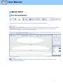
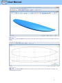
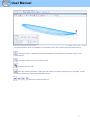

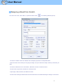

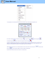
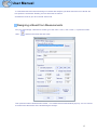
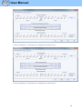
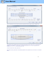
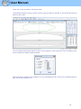
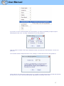
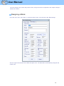
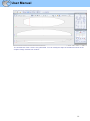
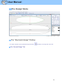
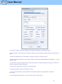
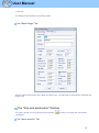
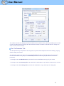
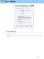
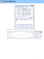

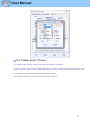
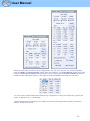
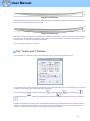
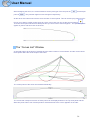
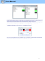
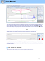
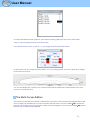
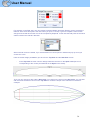
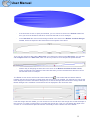
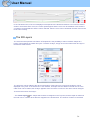
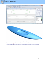
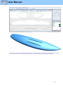
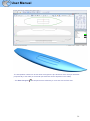
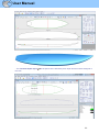
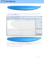
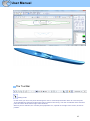
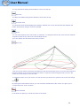
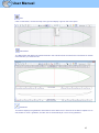
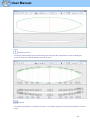
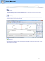
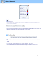
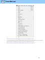
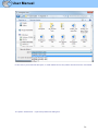
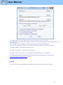
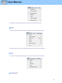
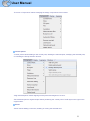
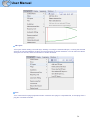
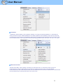
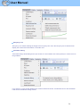
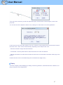
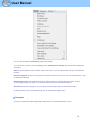
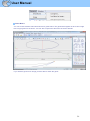
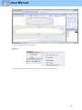
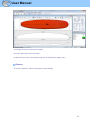
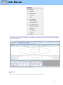
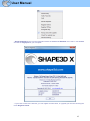
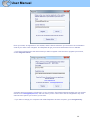
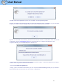
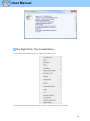
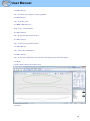
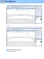
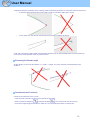
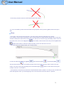
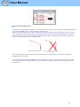
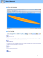
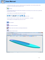
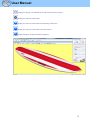
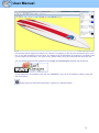
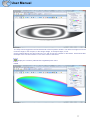
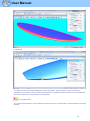
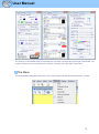

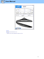
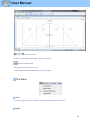
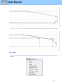

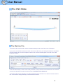
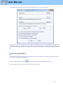
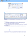
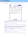
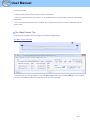
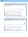
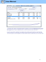
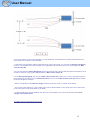

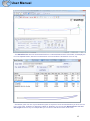
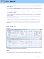
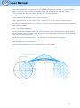
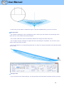
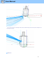
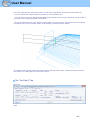
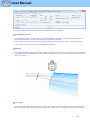
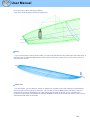

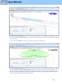
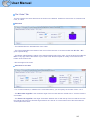
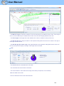
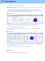
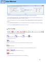
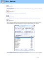
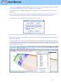
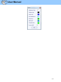
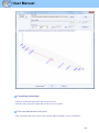
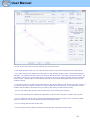
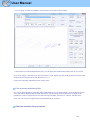
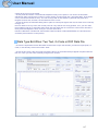
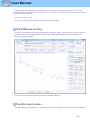
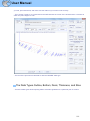
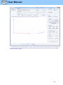
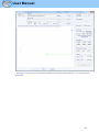
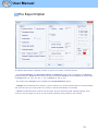
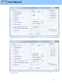

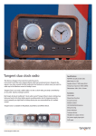


![[U4.42.02] Macro-commande MACR_CARA_POUTRE](http://vs1.manualzilla.com/store/data/006351730_1-da0dd278ec0085c1605c9c9e5244682c-150x150.png)