1
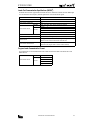
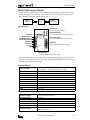
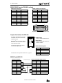
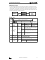
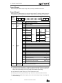
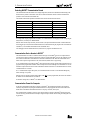
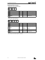
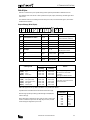
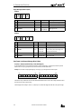
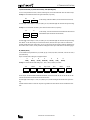
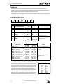
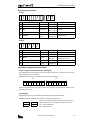
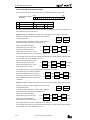
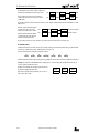
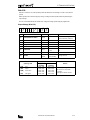
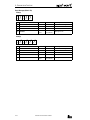
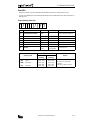
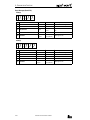
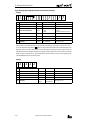
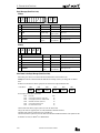
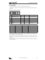
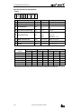
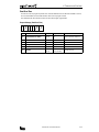
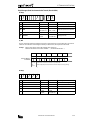
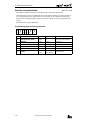
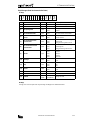
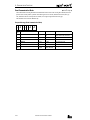
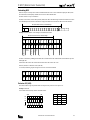
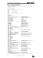
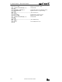
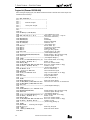
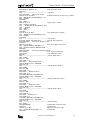
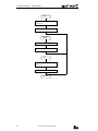
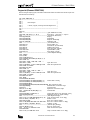
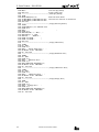
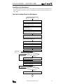
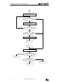
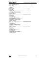
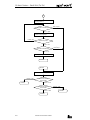
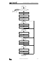
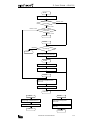
/
4: COMMUNICATION FUNCTIONS
Read User Communication Transmit/Receive Buffer
◆ MICRO3C Only ◆
While user communication is performed through the loader port, the transmit and receive buffers store the data of the last
communication. The data stored in the transmit and receive buffers can be read through the data link terminals using the
read user communication transmit/receive buffer command.
This command can be used on the MICRO3C only.
Request Message (Read User Communication Transmit/Receive Buffer)
05h **
(1)
(1)
** 30h 52h **
(2)
(3) (4) (5)
**
**
**
**
**
(6)
**
**
(7)
Communication control character
** 0Dh
(8)
(9)
1 byte
ENQ (05h)
Enquiry
Device number 0 through 31
Device number 255 (all devices)
Discontinued
(2)
Communication device number
2 bytes
00 - 1F
FF
(3)
(4)
Continuation
1 byte
0 (30h)
Command
1 byte
R (52h)
Read data
User communication receive buffer
User communication transmit buffer
First address to read data
(Nth byte in the 200-byte buffer)
Byte count of data to read
200 (C8h) bytes maximum + 1h
(5)
Data type
1 byte
G (47h)
g (67h)
(6)
Operand number
4 bytes
0000 - 0199
(7)
Data length
2 bytes
01 - C9
(8)
BCC
2 bytes
00 - 7F
Block check character
(9)
Terminator
1 byte
2 bytes
CR (0Dh)
CR LF (0Dh 0Ah)
Message end code
(7) Data length
Specify the byte count of the data to read plus one as a data length. Since a 2-byte ASCII code is attached to the beginning
of the data codes in the reply message, one byte must be added to the data length in the request message. The additional 2byte ASCII code represents the byte count of read data (see the next page).
The transmit/receive buffer has a capacity of 200 (C8h) bytes. When reading the entire data in the transmit/receive buffer,
specify C9 (43h 39h) as a data length.
4-28
COMPUTER LINK SYSTEM USER’S MANUAL