1
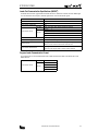
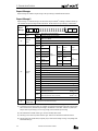
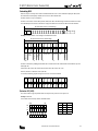
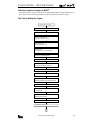
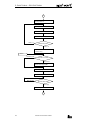
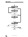
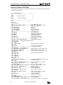
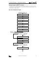
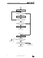
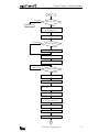
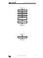
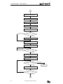
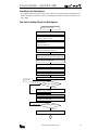
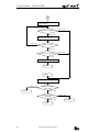
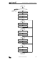
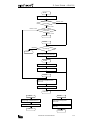
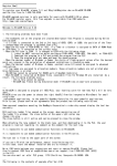
/
12: SAMPLE PROGRAM — READ 1 BIT
Read 1 Bit to Monitor Input I0
This example demonstrates a program to monitor the status of input I0 in the MICRO3 of device number 0 and display the
monitored ON/OFF status on the computer screen. Monitoring the input status is possible whether MICRO3 is running or
stopped.
Flow Chart for Reading 1 Bit to Monitor Input I0
Read 1 bit to monitor input I0
Clear the screen.
Open the communication line.
(Even parity, 7 data bits, 1 stop bit)
Set control characters.
(ENQ$, ACK$, NAK$, CR$)
Set transmit data.
(DNO$, FLK$, CND$, DTK$, OPN$)
Create request message.
REQ$=ENQ$+DNO$+FLK$+CND$+DTK$+OPN$
Determine the request message length.
Clear the BCC calculation buffer to 0.
Calculate the BCC.
Convert the BCC calculation results into character string.
Append BCC$ and CR$ to the request message.
COMLOOP
Data not received
Check the receive buffer.
Data received
Read data from the receive buffer.
Enable sending (request to send).
Write data into the transmit buffer.
Buffer not empty
Check the transmit buffer.
Buffer empty
Prohibit sending.
1
COMPUTER LINK SYSTEM USER’S MANUAL
12-1