1
/
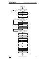
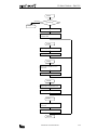
TABLE OF CONTENTS
Chapter 1:
General
Features . . . . . . . . . . . . . . . . . . . . . . . . . . . . . . . . . . . . . . . . . . . . . . . . . . . . . . .
Functions . . . . . . . . . . . . . . . . . . . . . . . . . . . . . . . . . . . . . . . . . . . . . . . . . . . . . .
Requirements . . . . . . . . . . . . . . . . . . . . . . . . . . . . . . . . . . . . . . . . . . . . . . . . . . .
Computer Link 1:1 Communication (MICRO3) . . . . . . . . . . . . . . . . . . . . . . . . . . . .
Computer Link 1:N Communication (MICRO3) . . . . . . . . . . . . . . . . . . . . . . . . . . . .
Computer Link 1:N Communication (MICRO3C) . . . . . . . . . . . . . . . . . . . . . . . . . . .
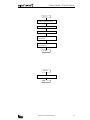
Chapter 2:
Specifications
Communication Specifications . . . . . . . . . . . . . . . . . . . . . . . . . . . . . . . . . . . . . . .
MICRO3 Communication Specifications (Loader Port) . . . . . . . . . . . . . . . . . . . . . . .
Program Loader Communication Format . . . . . . . . . . . . . . . . . . . . . . . . . . . . . . . .
Communication Specifications . . . . . . . . . . . . . . . . . . . . . . . . . . . . . . . . . . . . . . .
RS232C/RS485 Converter FC2A-MD1 . . . . . . . . . . . . . . . . . . . . . . . . . . . . . . . . . .
Computer Link Interface Unit FC2A-LC1 . . . . . . . . . . . . . . . . . . . . . . . . . . . . . . . . .
RS232C Cable HD9Z-C52 . . . . . . . . . . . . . . . . . . . . . . . . . . . . . . . . . . . . . . . . . .
Chapter 3:
2-1
2-1
2-1
2-2
2-3
2-4
2-4
Communication Protocol
Communication Procedure . . . . . . . . . . . . . . . . . . . . . . . . . . . . . . . . . . . . . . . . . .
Message Format . . . . . . . . . . . . . . . . . . . . . . . . . . . . . . . . . . . . . . . . . . . . . . . . .
Request Messages . . . . . . . . . . . . . . . . . . . . . . . . . . . . . . . . . . . . . . . . . . . . . . .
Request Message 1 . . . . . . . . . . . . . . . . . . . . . . . . . . . . . . . . . . . . . . . . . . . . . .
Request Message 2 . . . . . . . . . . . . . . . . . . . . . . . . . . . . . . . . . . . . . . . . . . . . . .
Receive Timeout . . . . . . . . . . . . . . . . . . . . . . . . . . . . . . . . . . . . . . . . . . . . . . . . .
Reply Messages . . . . . . . . . . . . . . . . . . . . . . . . . . . . . . . . . . . . . . . . . . . . . . . . .
ACK Reply Message . . . . . . . . . . . . . . . . . . . . . . . . . . . . . . . . . . . . . . . . . . . . . . .
NAK Reply Message . . . . . . . . . . . . . . . . . . . . . . . . . . . . . . . . . . . . . . . . . . . . . .
Communication Device Number in Communication Message . . . . . . . . . . . . . . . . . .
Communication Processing Time . . . . . . . . . . . . . . . . . . . . . . . . . . . . . . . . . . . . .
Calculating the Communication Processing Time . . . . . . . . . . . . . . . . . . . . . . . . . .
Selecting MICRO3 Communication Format . . . . . . . . . . . . . . . . . . . . . . . . . . . . . . .
Communication Device Number in MICRO3 . . . . . . . . . . . . . . . . . . . . . . . . . . . . . .
Communication Format for Computer . . . . . . . . . . . . . . . . . . . . . . . . . . . . . . . . . .
Chapter 4:
1-1
1-1
1-1
1-2
1-4
1-5
3-1
3-1
3-2
3-2
3-3
3-3
3-4
3-4
3-5
3-6
3-7
3-7
3-8
3-8
3-8
Communication Functions
Write User Program . . . . . . . . . . . . . . . . . . . . . . . . . . . . . . . . . . . . . . . . . . . . . . . 4-1
Read User Program . . . . . . . . . . . . . . . . . . . . . . . . . . . . . . . . . . . . . . . . . . . . . . . 4-3
Write N Bytes . . . . . . . . . . . . . . . . . . . . . . . . . . . . . . . . . . . . . . . . . . . . . . . . . . . 4-5
Read N Bytes . . . . . . . . . . . . . . . . . . . . . . . . . . . . . . . . . . . . . . . . . . . . . . . . . . . 4-8
Write 1 Bit . . . . . . . . . . . . . . . . . . . . . . . . . . . . . . . . . . . . . . . . . . . . . . . . . . . . 4-13
Read 1 Bit . . . . . . . . . . . . . . . . . . . . . . . . . . . . . . . . . . . . . . . . . . . . . . . . . . . . 4-15
Read High-speed Counter Preset and Current Values . . . . . . . . . . . . . . . . . . . . . . 4-17
Read Error Code . . . . . . . . . . . . . . . . . . . . . . . . . . . . . . . . . . . . . . . . . . . . . . . . 4-19
Clear Operand Data . . . . . . . . . . . . . . . . . . . . . . . . . . . . . . . . . . . . . . . . . . . . . . 4-21
Read PLC Operating Status . . . . . . . . . . . . . . . . . . . . . . . . . . . . . . . . . . . . . . . . 4-23
Read Scan Time . . . . . . . . . . . . . . . . . . . . . . . . . . . . . . . . . . . . . . . . . . . . . . . . 4-25
Read PLC System Program Version . . . . . . . . . . . . . . . . . . . . . . . . . . . . . . . . . . . 4-27
Read User Communication Transmit/Receive Buffer . . . . . . . . . . . . . . . . . . . . . . 4-28
Clear and Start User Communication Data Monitor . . . . . . . . . . . . . . . . . . . . . . . 4-30
Read User Communication Status . . . . . . . . . . . . . . . . . . . . . . . . . . . . . . . . . . . 4-32
Read Communication Mode . . . . . . . . . . . . . . . . . . . . . . . . . . . . . . . . . . . . . . . . 4-34
COMPUTER LINK SYSTEM USER’S MANUAL
i
TABLE
OF
/
CONTENTS
Chapter 5:
BCC (Block Check Character)
Calculating BCC . . . . . . . . . . . . . . . . . . . . . . . . . . . . . . . . . . . . . . . . . . . . . . . . . . 5-1
Exclusive OR (XOR) . . . . . . . . . . . . . . . . . . . . . . . . . . . . . . . . . . . . . . . . . . . . . . . . 5-1
Flow Chart for Calculating BCC . . . . . . . . . . . . . . . . . . . . . . . . . . . . . . . . . . . . . . . 5-2
Chapter 6:
Sample Program — Write User Program
Chapter 7:
Sample Program — Read User Program
Chapter 8:
Sample Program — Write N Bytes
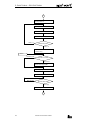
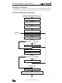
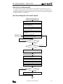
Write User Program from Computer to MICRO3 . . . . . . . . . . . . . . . . . . . . . . . . . . . . 6-1
Flow Chart for Writing User Program . . . . . . . . . . . . . . . . . . . . . . . . . . . . . . . . . . . . 6-1
Program List (Filename: WTPROG.BAS) . . . . . . . . . . . . . . . . . . . . . . . . . . . . . . . . . 6-8
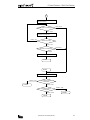
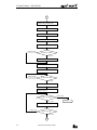
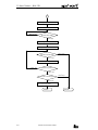
Read User Program from MICRO3 to Computer . . . . . . . . . . . . . . . . . . . . . . . . . . . . 7-1
Flow Chart for Reading User Program . . . . . . . . . . . . . . . . . . . . . . . . . . . . . . . . . . . 7-1
Program List (Filename: RDPROG.BAS) . . . . . . . . . . . . . . . . . . . . . . . . . . . . . . . . . 7-6
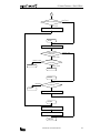
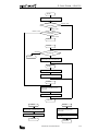
Write N Bytes to Data Registers . . . . . . . . . . . . . . . . . . . . . . . . . . . . . . . . . . . . . . 8-1
Flow Chart for Writing N Bytes to Data Registers . . . . . . . . . . . . . . . . . . . . . . . . . . . 8-1
Program List (Filename: WTNBYT.BAS) . . . . . . . . . . . . . . . . . . . . . . . . . . . . . . . . . . 8-5
Chapter 9:
Sample Program — Read N Bytes (DR)
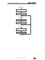
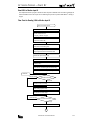
Read N Bytes from Data Registers . . . . . . . . . . . . . . . . . . . . . . . . . . . . . . . . . . . . 9-1
Flow Chart for Reading N Bytes from Data Registers . . . . . . . . . . . . . . . . . . . . . . . . 9-1
Program List (Filename: RDNBYT.BAS) . . . . . . . . . . . . . . . . . . . . . . . . . . . . . . . . . . 9-4
Chapter 10: Sample Program — Read N Bytes (Tim/Cnt)
Read N Bytes from Timer/Counter Current Value . . . . . . . . . . . . . . . . . . . . . . . . . 10-1
Flow Chart for Reading N Bytes from Timers . . . . . . . . . . . . . . . . . . . . . . . . . . . . . 10-1
Program List (Filename: RDTBYT.BAS) . . . . . . . . . . . . . . . . . . . . . . . . . . . . . . . . . 10-4
Chapter 11: Sample Program — Write 1 Bit
Write 1 Bit to Set or Reset Output Q0 . . . . . . . . . . . . . . . . . . . . . . . . . . . . . . . . . 11-1
Flow Chart for Writing 1 Bit to Set or Reset Output Q0 . . . . . . . . . . . . . . . . . . . . . 11-1
Program List (Filename: WT1BIT.BAS) . . . . . . . . . . . . . . . . . . . . . . . . . . . . . . . . . 11-4
Chapter 12: Sample Program — Read 1 Bit
Read 1 Bit to Monitor Input I0 . . . . . . . . . . . . . . . . . . . . . . . . . . . . . . . . . . . . . . . 12-1
Flow Chart for Reading 1 Bit to Monitor Input I0 . . . . . . . . . . . . . . . . . . . . . . . . . . 12-1
Program List (Filename: RD1BIT.BAS) . . . . . . . . . . . . . . . . . . . . . . . . . . . . . . . . . 12-4
Chapter 13: Troubleshooting
Communication Troubles . . . . . . . . . . . . . . . . . . . . . . . . . . . . . . . . . . . . . . . . . .
Trouble 1 . . . . . . . . . . . . . . . . . . . . . . . . . . . . . . . . . . . . . . . . . . . . . . . . . . . . . .
Trouble 2 . . . . . . . . . . . . . . . . . . . . . . . . . . . . . . . . . . . . . . . . . . . . . . . . . . . . . .
Trouble 3 . . . . . . . . . . . . . . . . . . . . . . . . . . . . . . . . . . . . . . . . . . . . . . . . . . . . . .
Trouble 4 . . . . . . . . . . . . . . . . . . . . . . . . . . . . . . . . . . . . . . . . . . . . . . . . . . . . . .
13-1
13-1
13-1
13-1
13-2
Chapter 14: Dimensions
RS232C/RS485 Converter FC2A-MD1 . . . . . . . . . . . . . . . . . . . . . . . . . . . . . . . . . 14-1
Computer Link Interface Unit FC2A-LC1 . . . . . . . . . . . . . . . . . . . . . . . . . . . . . . . . 14-2
MICRO3 Height with Computer Link Interface Cable . . . . . . . . . . . . . . . . . . . . . . . 14-2
ii
COMPUTER LINK SYSTEM USER’S MANUAL
/
1: GENERAL
Introduction
This manual introduces communication protocols and programs used for the MICRO3 and MICRO3C programmable controllers in the 1:1 and 1:N communication computer link systems.
Unless otherwise specified, all functions and descriptions relating the MICRO3 in this manual apply to both the
MICRO3 and MICRO3C. Where only MICRO3C is applicable, “MICRO3C only” is indicated.
The computer link system makes it possible to control and monitor a maximum of 32 MICRO3 units connected in a network
using a personal computer. Users can create a computer program to send and receive a user program to and from the
MICRO3, start and stop the MICRO3 operation, change data of data registers, change timer and counter preset values, and
collect data from the MICRO3. Operation status and error data can also be read to the computer. The collected data can be
stored and printed out by creating a proper program.
The CUBIQ software is available optionally to edit MICRO3 user programs and monitor MICRO3 operation in the 1:1 and 1:N
communication computer link systems.
Features
• A maximum of 32 MICRO3 units can be controlled and monitored from a computer.
• MICRO3 units can be connected to the 1:N communication computer link system using a shielded 2-core twisted pair
cable. The total length of the cable can be 200 meters (656 feet) at the maximum.
• Data can be read from MICRO3 units easily by sending an appropriate communication message from a computer.
• The 1:1 communication computer link system can be set up simply by connecting MICRO3 to a computer using computer link cable FC2A-KC2, which is 2 meters (6.56 feet) long. For the MICRO3C 1:1 computer link, see page 1-3.
Functions
• Write data from computer to MICRO3
User program
Inputs, outputs, internal relays, and shift registers in N bytes or 1 bit
Timer/counter preset values, data registers, and calendar/clock
• Read data from MICRO3 to computer
User program
Inputs, outputs, internal relays, and shift registers in N bytes or 1 bit
Timer/counter preset and current values, data registers, and calendar/clock
High-speed counter preset and current values
Error code
PLC operating status, timer/counter preset value change, user program protection, and MICRO3 base unit type
Scan time
PLC system program version
User communication transmit/receive buffer (MICRO3C only)
User communication status (MICRO3C only)
Communication mode (MICRO3C only)
• Clear operand data
Inputs, outputs, internal relays, timer/counter preset value changed data, timer/counter current values, and data register
All of inputs, outputs, internal relays, timer/counter current values, and data registers
Error code
Link formatting sequence
User communication data to start user communication data monitor (MICRO3C only)
Requirements
To create a computer program for the MICRO3 computer link system, prepare the following tools:
•
•
•
•
Programming language for computer, such as BASIC
Manual supplied with the computer
Manual for the OS such as MS-DOS (MS-DOS is a trademark of Microsoft Corporation.)
A protocol analyzer is recommended to check communication data.
COMPUTER LINK SYSTEM USER’S MANUAL
1-1
/
1: GENERAL
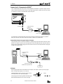
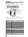
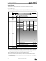
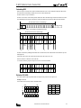
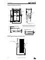
Computer Link 1:1 Communication (MICRO3)
The 1:1 communication computer link system is set up using MICRO3 and an IBM PC or compatible computer connected
with the computer link cable FC2A-KC2, 2m (6.56 ft.) long. When a longer distance is needed, the cable can be extended
up to 200m (656 ft.) using the 1:N communication computer link system.
To Loader Port
Computer Link Cable
FC2A-KC2
2m (6.56 ft.) long
To RS232C Port
D-sub 9-pin
Female Connector
Use FUN8 loader port communication mode setting to make sure that the communication parameters for the MICRO3
loader port are the same as the computer connected. For FUN8, see MICRO3 user’s manual EM317.
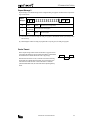
Communication between the program loader and computer
The program loader can also be connected to an IBM PC or compatible using computer link cable FC2A-KC2 for communication. An AC adapter is required to power the program loader. Connect the computer link cable to the loader cable connection port on the program loader. Plug the jack converter into the converter box on the computer link cable, and plug the
AC adapter into the jack converter.
Computer Link Cable
FC2A-KC2
2m (6.56 ft.) long
To RS232C Port
D-sub 9-pin
Female Connector
Jack Converter FC2A-CJ1
(included with computer link cable)
AC Adapter
AC Adapter
9.5
The RS232C/RS485 converter is powered by 24V DC source or
an AC adapter with 9V DC, 350mA output capacity.
The output plug of the AC adapter applicable to both the program
loader and RS232C/RS485 converter is shown on the right.
1-2
ø5.5
When using the program loader for communication with a computer, an AC adapter is required to power the program
loader. AC adapter output capacity: 5 to 6.5V DC, 4W
ø2.1
Polarity
+
Dimensions in mm.
COMPUTER LINK SYSTEM USER’S MANUAL
–
/
1: GENERAL
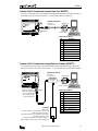
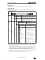
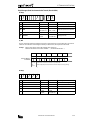
Computer Link 1:1 Communication through Loader Port (MICRO3C)
To set up a 1:1 computer link system, connect an IBM PC or compatible to the MICRO3C using the computer link cable 4C
(FC2A-KC4C). Set the protocol selector switch to 0, 2, or 4 to select loader protocol for the loader port.
Computer Link Cable 4C
To RS232C Port
FC2A-KC4C
3m (9.84 ft.) long
To Loader Port
(RS232C)
D-sub 9-pin
Female Connector
Cable Connector Pinouts
Pin
1
2
3
4
5
6
7
8
9
DCD
RXD
TXD
DTR
GND
DSR
—
CTS
—
Description
Data Carrier Detect
Receive Data
Transmit Data
Data Terminal Ready
Signal Ground
Data Set Ready
—
Clear to Send
—
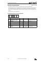
Computer Link 1:1 Communication through Data Link Terminals (MICRO3C)
A 1:1 computer link system can also be set up through the data link terminals on the MICRO3C using the computer link
cable 6C (FC2A-KC6C). Set the protocol selector switch to 2, 3, or 4 to select loader protocol for the data link terminals.
Computer Link Cable 6C
FC2A-KC6C
2m (6.56 ft.) long
To RS232C Port
RS232C/RS485
Converter
D-sub 9-pin
Female Connector
A B SG
Cable Connector Pinouts
(RS485)
B
SG
A
Connect the three spade terminals on the computer link
cable 6C to data link terminals A, B, and SG as indicated on the maker tubes.
AC Adapter
Output: 5V DC
Connect an AC adapter to the RS232C/RS485 converter in the
middle of the computer link cable 6C.
The computer link cable 6C is not supplied with an AC adapter,
which must be prepared by the user.
For applicable output plug of the AC adapter, see page 1-2.
Note: AC adapters for IDEC’s FA series PLCs cannot be used.
COMPUTER LINK SYSTEM USER’S MANUAL
Pin
1
2
3
4
5
6
7
8
9
—
RXD
TXD
—
GND
—
RTS
CTS
—
Description
—
Receive Data
Transmit Data
—
Signal Ground
—
Request to Send
Clear to Send
—
1-3
/
1: GENERAL
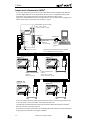
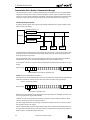
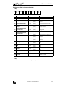
Computer Link 1:N Communication (MICRO3)
To set up a 1:N computer link system, connect a computer to RS232/RS485 converter using RS232C cable HD9Z-C52.
Connect the RS232C/RS485 converter to computer link interface units FC2A-LC1 using shielded twisted pair cables.
Connect MICRO3 to each computer link interface unit using computer link interface cable FC2A-KC3.
Supply power to the RS232C/RS485 converter by connecting a 24V DC source to terminals 6 and 7 or by plugging an AC
adapter to the DC IN jack. For specifications of the AC adapter, see page 1-2.
POWER
RS232C/RS485 Converter FC2A-MD1
132H × 110W × 34D mm
(5.917"H × 4.331"W × 1.339"D)
SD
RS485
SERIAL PORT
1
RS232C/RS485
CONVERTER
RD
Type FC2A-MD1
T
2
3
B
4
SG
5
FG
6
+
7
POWER SUPPLY
24V DC
RS232C SERIAL PORT
A
To RS232C Port
To RS232C Port
RS232C Cable
HD9Z-C52
1.5m (4.92 ft.) long
–
DC IN
+ –
24V DC or AC Adapter (9V DC, 350 mA)
1st Unit
Function selector switch: 0
FUN9: 0
D-sub 9-pin
Female
Connector
Shielded twisted pair cable 200 meters (656 feet) maximum
Core wire diameter 0.9 mm (0.035") minimum
2nd Unit
Function selector switch: 0
FUN9: 1
A B SG FG
Computer Link Interface Cable
FC2A-KC3
100 mm (3.937") long
A B SG FG
Computer Link Interface Unit
FC2A-LC1
69.5H × 55W × 35.5D mm
(2.736"H × 2.165"W × 1.398"D)
Nth Unit (N ≤ 32)
Function selector switch: 0
FUN9: N–1
3rd Unit
Function selector switch: 0
FUN9: 3
A B SG FG
A B SG FG
In place of the computer link interface cable FC2A-KC3, loader cable FC2A-KL1 (2m/6.56 ft. long) or FC2A-KL2 (5m/
16.4 ft. long) can also be used to connect MICRO3 to the computer link interface unit.
Use FUN8 loader port communication mode setting to make sure that the communication parameters for the MICRO3
loader port are the same as the computer connected.
Select a unique device number, from 0 through 31, for each MICRO3 using FUN9 PLC address for network communication
on the program loader, and transfer the user program to the MICRO3.
1-4
COMPUTER LINK SYSTEM USER’S MANUAL
/
1: GENERAL
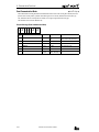
Computer Link 1:N Communication (MICRO3C)
Unlike the computer link 1:N communication system for the MICRO3, shielded twisted pair cables from the RS232C/
RS485 converter can be connected to data link terminals on the MICRO3C directly, without the need for the computer link
interface units and computer link interface cables.
To set up a 1:N computer link system, connect a computer to RS232C/RS485 converter using RS232C cable HD9Z-C52.
Connect the RS232C/RS485 converter to MICRO3C units using shielded twisted pair cables.
Supply power to the RS232C/RS485 converter by connecting a 24V DC source to terminals 6 and 7 or by plugging an AC
adapter to the DC IN jack. For specifications of the AC adapter, see page 1-2.
RS232C/RS485 Converter FC2A-MD1
132H × 110W × 34D mm
(5.917"H × 4.331"W × 1.339"D)
POWER
SD
RS485
SERIAL PORT
1
RS232C/RS485
CONVERTER
RD
Type FC2A-MD1
T
2
3
B
4
SG
5
FG
6
+
7
POWER SUPPLY
24V DC
To RS232C Port
RS232C SERIAL PORT
A
D-sub 25-pin
Male
Connector
–
DC IN
To RS232C Port
RS232C Cable
HD9Z-C52
1.5m (4.92 ft.) long
D-sub 9-pin
Female
Connector
+ –
24V DC or AC Adapter (9V DC, 350 mA)
1st Unit
2nd Unit
Function selector switch: 0
Protocol selector switch: 2, 3, or 4
FUN9: 0
Function selector switch: 0
Protocol selector switch: 2, 3, or 4
FUN9: 1
A B SG
A B SG
Shielded twisted pair cable 200m (656 ft.) maximum
Nth Unit (N≤32)
3rd Unit
Function selector switch: 0
Protocol selector switch: 2, 3, or 4
FUN9: N–1
Function selector switch: 0
Protocol selector switch: 2, 3, or 4
FUN9: 2
A B SG
A B SG
Select a unique device number, from 0 through 31, for each MICRO3C using FUN9 PLC address for network communication on the program loader, and transfer the user program to the MICRO3C.
COMPUTER LINK SYSTEM USER’S MANUAL
1-5
/
1: GENERAL
1-6
COMPUTER LINK SYSTEM USER’S MANUAL
/
2: SPECIFICATIONS
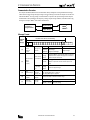
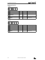
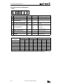
Loader Port Communication Specifications (MICRO3)
The MICRO3 base unit and the program loader have RS485 interface to communicate with each other in the RS485 signal
level. To communicate with a computer, the RS485 signals must be converted into RS232C signals.
Electrical Characteristics
Communication Method
Synchronization
Communication Configuration
Baud Rate
Communication Format
Data Bits
DTR/DSR Control
Maximum Cable Length
Receive Timeout
Communication Device Number
Compliance with EIA standard RS485
Half-duplex
Start-stop synchronization
1:N
1200, 2400, 4800, 9600, 19200 bps (Default: 9600 bps)
Start bit
1
Data bit
7, 8 (Default: 7)
Parity bit
Even, Odd, None (Default: Even)
Stop bit
1, 2 (Default: 1)
Available (when using the RS232C/RS485 converter)
200m (656 ft.) total using twisted pair cable
10 to 2550 msec (10 msec increments) designated using FUN8
MICRO3 base unit receive timeout default value 500 msec
0 through 31 (Default: 0)
255 (used by the program loader to access all device numbers)
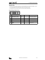
Program Loader Communication Format
The program loader uses a fixed communication format of baud rate and data bits which are the default values of the
MICRO3 base unit.
Baud Rate
Communication Format
Data Bits
9600 bps
Start bit
Data bit
Parity bit
Stop bit
1
7
Even
1
COMPUTER LINK SYSTEM USER’S MANUAL
2-1
/
2: SPECIFICATIONS
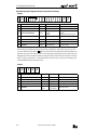
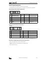
Loader Port Communication Specifications (MICRO3C)
The loader port on the MICRO3C has RS232C interface to communicate with a computer and other RS232C equipment
directly.
Standards
Maximum Cable Length
Baud Rate
Data Bits
Parity
Communication
Stop Bits
Parameters
Receive Timeout
Connection to Program Loader
Connection to RS232C Equipment
EIA RS232C
15m (49.2 ft.)
1200, 2400, 4800, 9600, 19200 bps
7 or 8 bits
Odd, Even, None
1 or 2 bits
10 to 2550 msec
(In the user communication, receive timeout is disabled when 2550 msec is
selected.)
Using optional loader cable 3C (FC2A-KL3C)
Using optional user communication cable 1C (FC2A-KP1C) or other cables
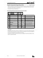
Data Link Terminal Communication Specifications (MICRO3C)
The MICRO3C can communicate with a computer through the data link terminals in a 1:N computer link configuration
using the RS232C/RS485 converter.
Standards
Recommended Cable
Conductor Resistance
Shield Resistance
Maximum Cable Length
EIA RS485 (termination resistor is not required)
ø0.9 mm shielded twisted cable
85 Ω/km maximum
12 Ω/km maximum
200m (656 ft.)
Isolation
Between data link terminals of multiple MICRO3C units: Not isolated
Expansion or data link communication:
19200 bps (fixed)
Loader protocol communication:
9600 bps (fixed)
Expansion link: Master station normal scan time + approx. 9 to 10 msec
Data link:
Master station normal scan time + approx. 12.5 to 13 msec + Slave
station scan time
Using optional loader cable 4C (FC2A-KL4C)
Baud Rate
Communication Delay
Connection to Program Loader
2-2
COMPUTER LINK SYSTEM USER’S MANUAL
/
2: SPECIFICATIONS
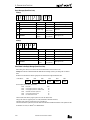
RS232C/RS485 Converter FC2A-MD1
The RS232C/RS485 converter FC2A-MD1 is used with the MICRO3C and the MICRO3 to convert data signals between EIA
RS232C and EIA RS485. This converter makes it possible to connect a host device with RS232C interface to multiple
MICRO3C and MICRO3 programmable controllers using one cable.
RS485
Signal Level
RS232C
Signal Level
Converter
Parts Description
Power Indicator
POWER
RS485
SERIAL PORT
Termination Resistor
Transmit/Receive Data A
Transmit/Receive Data B
Signal Ground
Frame Ground
Vcc (+24V)
GND
1
RS232C/RS485
CONVERTER
SD
Transmit Data Indicator
RD
Goes on when RS232C transmit data (pin #2) is on
Receive Data Indicator
Type FC2A-MD1
T
2
A
3
B
4
SG
5
FG
6
+
7
POWER SUPPLY
24V DC
RS232C SERIAL PORT
RS485 I/O
Goes on when power is supplied
Goes on when RS232C receive data (pin #3) is on
RS232C I/O
Connect to the RS232C port on the computer
–
DC IN
AC Adapter Jack
Connect AC adapter to supply 9V DC, 350mA
Note: The FC2A-MD1 contains a 220Ω termination resistor on the RS485 line, eliminating the need for an external termination resistor. To use the internal termination resistor, connect terminal T to terminal B. When the termination resistor is
not needed, disconnect terminal T from terminal B.
General Specifications
Rated Power Voltage
Current Draw
Operating Temperature
Storage Temperature
Operating Humidity
Vibration Resistance
Shock Resistance
Dielectric Strength
Insulation Resistance
Noise Resistance
Weight
Power terminals
24V DC ±20% (Ripple 10% maximum)
DC IN adapter jack
9V DC, 350mA supplied from AC adapter
Power terminals: Approx. 40 mA at the rated voltage
0 to 60°C
–20 to +70°C
45 to 85% RH (no condensation)
5 to 55 Hz, 60 m/sec2, 2 hours each in 3 axes
300 m/sec2, 3 shocks each in 3 axes
1500V AC, 1 minute between live parts and dead parts
10 MΩ minimum between live parts and dead parts (500V DC megger)
Power terminals: ±1 kV, 1 µsec (using noise simulator)
Approx. 550g
Serial Interface Specifications
Standards in Compliance
Communication Method
Communication Configuration
Communication Cable
Communication Baud Rate
Slave Stations
Maximum Cable Length
EIA standard RS232C (D-sub 25-pin female connector)
EIA standard RS485 (screw terminals)
Half-duplex
1:N (N ≤ 32)
Shielded twisted-pair cable
9600 bps (fixed)
32 slave stations maximum (RS485 line)
RS232C: 15m (49.2 ft.)
RS485: Total 200m (656 ft.)
COMPUTER LINK SYSTEM USER’S MANUAL
2-3
/
2: SPECIFICATIONS
RS232C/RS485 Converter FC2A-MD1, continued
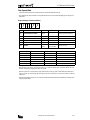
RS485 Terminal Arrangement
Terminal No.
1
2
3
4
5
6
7
8
9
10
Symbol
SG
SD A
SD B
FG
SG
RD A
RD B
FG
+
–
RS232C Connector Pin Arrangement
Name
Signal Ground
Transmit Data A
Transmit Data B
Frame Ground
Signal Ground
Receive Data A
Receive Data B
Frame Ground
Vcc (+24V)
GND
Pin No.
1
2
3
4
5
6
7
8-25
Symbol
GND
TXD
RXD
RTS
CTS
(NC)
GND
(NC)
Name
Frame Ground
Transmit Data
Receive Data
Request to Send
Clear to Send
Unused
Signal Ground
Unused
13
1
25
14
25-pin Female Connector on RS232C/RS485 Converter
Computer Link Interface Unit FC2A-LC1
One computer link interface unit is used with
each MICRO3 unit in the 1:N communication
computer link system.
Note: MICRO3C does not require the computer
link interface unit to set up the 1:N communication computer link system.
RS-485 Terminals
A
B
SG
Connect to the RS232C/RS485 converter.
FG
LINK
Cable Connector
Connect the computer link interface cable
FC2A-KC3 to MICRO3.
MICRO3
COMPUTER
LINK UNIT
TYPE: FC2A-LC1
The computer link interface unit cannot be
connected to the program loader.
RS485 Terminal Arrangement
Symbol
A
B
SG
FG
For dimensions of the computer link interface unit, see page 14-2.
Name
Transmit/Receive Data A
Transmit/Receive Data B
Signal Ground
Frame Ground
RS232C Cable HD9Z-C52
Connector for Computer
Symbol
DCD
RXD
TXD
DTR
GND
DSR
RTS
CTS
RI
Pin No.
1
2
3
4
5
6
7
8
9
D-sub 9-pin female connector
2-4
Connector for RS232C/RS485 Converter
1.5m (4.92 ft.) long
Pin No.
1
2
3
4
5
6
8
20
7
Symbol
GND
TXD
RXD
RTS
CTS
DSR
DCD
DTR
GND
D-sub 25-pin male connector
COMPUTER LINK SYSTEM USER’S MANUAL
Name
Frame Ground
Transmit Data
Receive Data
Request to Send
Clear to Send
Data Set Ready
Data Carrier Detect
Data Terminal Ready
Signal Ground
/
3: COMMUNICATION PROTOCOL
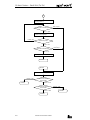
Communication Procedure
The computer and MICRO3/MICRO3C base unit communicate data by sending and receiving communication messages,
which consist of request messages and reply messages. The request message is sent from the computer to write data to or
read data from MICRO3. The reply message is sent from MICRO3 in response to the request message from the computer.
Communication is always initiated by the computer by sending a request message to MICRO3, which then returns a reply
message to the computer. MICRO3 cannot initiate communication.
Request Message
Computer or
Program Loader
MICRO3
MICRO3C
Reply Message
Message Format
Communication
Message
(1)
(2)
BCC (Block Check Character) Calculation Range
(1)
(2)
Communication
control
character
(1 byte)
Communication
device
number
(2 bytes)
(3)
Message start
character
Device number
to send request
to
(3)
Data
(variable length)
(4)
BCC
(2 bytes)
Device number
to send reply
from
Communication
command,
data type, etc.
Block check
character
(5)
Terminator
(1 or 2 bytes)
Message
end code
(4)
(5)
ENQ (05h)
Enquiry
Request message
ACK (06h)
NAK (15h)
Acknowledge
Negative acknowledge
Reply message
00 (0)
through
1F (31)
Designates MICRO3 device number (FUN9) to which the
computer sends a request message in the 1:N communication computer link system.
Used in the 1:1 communication computer link system.
MICRO3 of any device number receives request message.
FF (255)
00 (0)
Indicates the device number (FUN9) of MICRO3 which
through
returns the reply message.
1F (31)
Depends on each command.
See “Request Messages” on page 3-2.
See “Reply Messages” on page 3-4.
Exclusive OR (XOR) of the BCC calculation range.
CR (0Dh)
CR (0Dh) + LF (0Ah)
Default
Selected using FUN8 (loader port communication mode setting)
COMPUTER LINK SYSTEM USER’S MANUAL
3-1
/
3: COMMUNICATION PROTOCOL
Request Messages
Request messages are available in request message 1 and request message 2 with different data structures.
Request Message 1
Request message 1 is a command message to be sent from the computer to MICRO3, containing a command. The data type
code included in the request message determines the function. The data structure of request message 1 is shown below:
Request
Message 1
ENQ
05h
Device
(1)
Continuation
(1 byte)
(2)
Command
(1 byte)
(1) (2) (3)
(4)
BCC
0 (30h)
1 (31h)
Discontinued (no message follows)
Continued (another message follows)
W (57h)
Write data to MICRO3
R (52h)
Read data from MICRO3
C (43h)
Clear data from MICRO3
X (58h)
Input
t (74h)
Output
M (4Dh)
Internal relay
R (52h)
D (44h)
U (55h)
P (50h)
S (53h)
N (4Eh)
K (4Bh)
W (57h)
E (45h)
Z (5Ah)
I (49h)
N-byte
Shift register
x (78h)
designation
Timer
y (79h)
(preset value)
Counter
m (6Dh)
(preset value)
Data register
r (72h)
High-speed counter (preset value + current
User program
PLC operating status
PLC system program version
Scan time
Calendar/clock
Error code
System reset
Link formatting sequence
G (47h)
User communication receive buffer
MICRO3C only
g (67h)
User communication transmit buffer
MICRO3C only
A (41h)
19,200 bps (clear data)
MICRO3C only
B (42h)
9,600 bps (clear data)
User communication status (read data)
MICRO3C only
MICRO3C only
H (48h)
Communication mode (read data)
MICRO3C only
C (43h)
(4)
Data type
(1 byte)
Data
(variable length)
N-byte
designation
Y (59h)
T (54h)
(3)
Timer
(current
value)
Counter
Terminator
c (63h)
Input
Output
Internal relay
1-bit
designation
Shift register
value)
Data (depends on command and data type)
(1) “Continued” is used in request message 1 for writing the user program to inform MICRO3 that another request message
will be sent successively. In all other request messages, “discontinued” is used. When “continued” is specified, the
computer sends a request message, receives a reply message, and sends another request message.
(2) The command code is available in three types; write data, read data, and clear data.
(3) The data type code selects an operand or function. Upper- and lower-case characters have different functions.
(4) The data specifies the operand number, the quantity of bytes of the data for reading or writing, etc. depending on the
command and data type.
3-2
COMPUTER LINK SYSTEM USER’S MANUAL
/
3: COMMUNICATION PROTOCOL
Request Message 2
Request message 2 is a command message used for writing and reading user programs. The data structure of request message 2 is shown below:
Request
Message 2
(1)
(2)
ENQ
05h
Device
(1)
Continuation
(1 byte)
Data
(variable length)
Data
(1 byte)
(2)
0 (30h)
BCC
Terminator
Discontinued (no message follows)
User program (write user program)
R (52h)
Read user program
(1) “Discontinued” is used for both writing and reading user programs to inform MICRO3 that no request message will be
sent successively.
(2) The data length is variable for writing user programs and is 1-byte long (“R”) for reading user programs.
Receive Timeout
When a request message contains an interval of 500 msec or more between onebyte character data and the next one-byte character data, MICRO3 understands that
the communication is canceled and does not return a reply message.
When the interval is 500 msec or more, extend the receive timeout value using
FUN8 (loader port communication mode setting). The receive timeout can be
selected between 10 and 2550 msec in 10-msec increments. To enable the
optional communication mode, turn on the mode selection input designated by
FUN8.
COMPUTER LINK SYSTEM USER’S MANUAL
Data
Data
≤ 500 msec
3-3
/
3: COMMUNICATION PROTOCOL
Reply Messages
Reply messages are available in ACK reply message and NAK reply message with different data structures.
ACK Reply Message
The ACK reply message is a reply or response to the request message and is sent from MICRO3 to the computer when communication is completed normally.
ACK
Reply
Message
ACK
06h
Device
(1)
0 (30h)
1 (31h)
(1)
Command
(1 byte)
2 (32h)
(2)
BCC
Terminator
OK: Discontinued
All communication is completed normally (end of processing).
Communication in reply to request is completed normally and
OK: Continued
another reply message follows when reading a user program.
Communication device number, command, data type, data, or continuation code is not within the range suppor ted by MICRO3 or
NG: Error
does not match its status. When this error occurs, communication
is halted without regard to the continuation code.
When request command is W or C
No data exists. (0 byte)
OK
The data length depends on the request
reply
When request command is R
command (variable length).
NG code (2 bytes)
NG
Code
0 (30h)
to
9 (39h)
(2)
Data
(variable
length)
or
A (41h)
to
F (46h)
NG
reply
Error
Cause
00
Expansion station error
Communication attempted to expansion station
01
Program size error
Improper write/read program size
02
Protect error
Protected against write/read in MICRO3
03
RUN error
Writing user program attempted while MICRO3 is
running
04
CRC error
User program CRC code not matched
06
Data range error
Invalid data range designated
07
Timer/counter preset
value change error
Preset value change attempted to timer or
counter with preset value designated by data register
08
Calendar/clock data error
Invalid value written to calendar/clock
09
Data clear error
Designated data cannot be cleared
10
Data error
Invalid data other than 0 (30h) - 9 (39h) or
A (41h) - F (46h)
11
Setting error
Incorrect setting for user communication
(MICRO3C only)
(1) The command code indicates whether the request command is completed normally or not and also whether another
reply message will be sent successively.
When reading a user program from MICRO3, reply message 1 is returned in response to request message 1 and reply
message 2 is returned in response to request message 2. Reply message 1 contains command 1 (OK: continued) to
inform the computer that another reply message follows. All other reply messages contain command 0 (OK: discontinued) to indicate that no reply message follows when communication is completed normally.
(2) When an OK reply is returned in response to request command R (read data), the read data is included in this place.
When an NG reply is returned, the cause of error exists in MICRO3. See page 13-2.
3-4
COMPUTER LINK SYSTEM USER’S MANUAL
/
3: COMMUNICATION PROTOCOL
NAK Reply Message
When an error is found during communication, a NAK reply message is sent from MICRO3 to the computer.
NAK
Reply
Message
(1)
NAK
15h
Device
(1)
Command
(2)
BCC
Terminator
0 (no meaning): dummy data for consistent communication format
Depending on the communication error, an error code is set in this place.
Error
Code
(2)
Communication
error code
(2 bytes)
Error Type
Error Contents
00
BCC error
Appended BCC code does not match BCC calculated
value of received data.
01
Frame error
Quantity of received bits differs from the preset
value (stop bit is 0 for example).
02
Data send/receive error
Parity error or overrun error occurred.
03
Command error
Unsupported request message is received.
04
Procedure/data quantity error
Received request message does not match the
expected data (including quantity of data).
(1) The command code in the NAK reply message is always 0.
(2) The next two bytes indicate the communication error code.
COMPUTER LINK SYSTEM USER’S MANUAL
3-5
/
3: COMMUNICATION PROTOCOL
Communication Device Number in Communication Message
The communication device number is an address number 0 through 31 of the MICRO3 base unit in a 1:N communication
computer link network. The device number is stored in the FUN9 area of the user program in the MICRO3 base unit. The
computer uses the device number to differentiate various MICRO3 base units that it communicates with. When the communication device number in the request message matches the value stored in FUN9, MICRO3 returns a reply message.
Communication Procedure Schematic
For example, when the computer sends a request message including communication device number 2, MICRO3 of device
number 2 returns a reply message.
Communication Device # = 2
Request Message
RS232C/RS485 Converter
Computer
Reply Message
MICRO3
FUN9 = 1
MICRO3
FUN9 = 2
MICRO3
FUN9 = 3
A communication device number must also be included in the request message in the 1:1 computer link system. If communication device number 255 is included in the request message, MICRO3 receives the request message regardless of the
FUN9 value and returns a reply message.
Since the program loader sends a request message including device number 255, the program loader can communicate
with MICRO3 base units of any device number and can change the device number of MICRO3 base units.
To select a MICRO3 base unit in a computer link network, include the desired communication device number in the request
message.
Request message
05h
Device
(1) (2) (3)
(4)
BCC
Terminator
Include the MICRO3 device number to communicate with.
Example: To specify communication device number 10
Convert decimal value 10 into hexadecimal value 0Ah. Convert each character of the hexadecimal value into hexadecimal
ASCII codes of 30h and 41h. Include the two-byte code in place of the device number in the request message.
10 (0Ah) → ASCII codes (30h 41h)
Request message
05h 30h 41h (1) (2) (3)
(4)
BCC
Terminator
Device number to communicate with.
Note: The device number of MICRO3 is selected using FUN9 on the program loader. After changing the FUN9 value, transfer the user program from the program loader to MICRO3.
All MICRO3 base units in a computer link network must have a unique device number 0 through 31. Make sure that the
same device number does not exist in a computer link network.
If the device number included in the request message is not found in the computer link network, no response is returned
from any MICRO3 base unit to the computer.
The device number of MICRO3 can also be changed using the CUBIQ software. Change the FUN9 communication device #
in the FUN table. In the transfer menu box, select device number 255, and transfer the user program from the computer to
MICRO3 using the 1:1 communication computer link system.
3-6
COMPUTER LINK SYSTEM USER’S MANUAL
/
3: COMMUNICATION PROTOCOL
Communication Processing Time
When monitoring the MICRO3 status in a computer link system, the communication processing time between the computer
and MICRO3 is required in addition to the processing times at the computer and MICRO3. When setting up a computer link
system, the communication processing time must be taken into consideration.
Calculating the Communication Processing Time
1. From the communication format, calculate the quantity of data in bytes that can be sent and received per second:
Bytes of data per second = Baud rate (bps) ÷ Communication bit count
Communication bit count = Start bit + Data bits + Parity bit + Stop bit
(Parity bit: None = 0, Even or Odd = 1)
2. Calculate the byte count to be communicated.
Communication byte count = Byte count to send + Byte count to receive
3. Calculate the communication processing time using these values.
Communication processing time = Communication byte count ÷ Bytes of data per second
Example: Read data register 1-word (2 bytes) data from 10 MICRO3 base units with the default communication format.
1. The default communication format values are:
Baud rate
Start bit
Data bits
Parity bit
Stop bit
9600 bps
1 bit
7 bits
Even (1 bit)
1 bit
Therefore, the communication bit count is 10 bits (= 1 + 7 + 1 + 1).
The characters (bytes) of data communicated per second are 960 bytes (= 9600 ÷ 10).
2. The byte count of the request message is:
Communication control character
Communication device number
Continuation code
Data
BCC
Terminator
Total
The byte count of the reply message is:
1 byte
2 bytes
1 byte
8 bytes
2 bytes
1 byte
15 bytes
Communication control character
Communication device number
Command
Data
BCC
Terminator
Total
1 byte
2 bytes
1 byte
4 bytes *
2 bytes
1 byte
11 bytes
Therefore, the communication byte count is 26 bytes (= 15 + 11).
* Although reading 2 bytes of data is specified in the request message, the data of a data register consists of 4 characters and 4 bytes of data is returned in the reply message.
3. The communication processing time for one MICRO3 base unit is 0.027 sec (= 26 ÷ 960).
Since the communication is executed for 10 MICRO3 base units, the total communication processing time will be 0.27
sec (= 0.027 × 10).
For calculating the byte counts of the request and reply messages, see chapter 4.
COMPUTER LINK SYSTEM USER’S MANUAL
3-7
/
3: COMMUNICATION PROTOCOL
Selecting MICRO3 Communication Format
The communication format for MICRO3 can be changed using FUN8 (Loader Port Communication Mode Setting). This
function makes it possible to communicate with a device which has an RS232C interface with fixed communication
parameters such as baud rate and terminator code.
The available communication parameters and default values selected with FUN8 are listed below:
Communication Parameter
Baud Rate
Terminator Code
Data Bits
Parity Check
Stop Bits
Mode Selection Input
Receive Timeout
Option
Default (Standard Mode)
1200, 2400, 4800, 9600, 19200 bps
0D (CR), 0D 0A (CR LF)
7, 8 bits
None, Even, Odd
1, 2 bits
I0 to I15
10 to 2550 (10-msec increments)
9600 bps
0D (CR)
7 bits
Even
1 bit
None
500 msec
For setting FUN8 using the program loader, see MICRO3 User’s Manual EM317. For changing FUN table settings using the
CUBIQ software, see CUBIQ User’s Manual EM292.
When the mode selection input selected by FUN8 is turned on, the optional communication mode is enabled. When the
mode selection input is off, the default communication mode is enabled. When using the program loader to communicate
with MICRO3, use the standard communication mode of all default values.
After changing the FUN8 communication format, transfer the user program to the MICRO3 base unit.
Communication Device Number in MICRO3
The communication device number is an address number 0 through 31 of the MICRO3 base unit in a computer link network. The device number is stored in the FUN9 area of the user program in the MICRO3 base unit. The computer uses the
device number to differentiate various MICRO3 base units that it communicates with. When the communication device
number in the request message matches the value stored in FUN9, MICRO3 returns a reply message.
To set a communication device number in MICRO3, change the FUN9 value using the program loader and transfer the user
program from the program loader to MICRO3. Allocate a unique device number 0 through 31 to each MICRO3 in a 1:N communication computer link network. If the same communication number is found at two or more MICRO3 units in a network,
a communication error will result.
In a 1:1 communication computer link system, use of communication device number 0 is recommended although any
number 0 through 31 is possible.
When the entire user program is deleted using the DEL, END,
the default value of communication device number 0.
keys on the program loader, the FUN9 is also cleared to
For details of setting FUN9, see MICRO3 User’s Manual EM317.
Communication Format for Computer
Set the same communication format for the computer as for MICRO3. The communication format for the computer is
selected by the parameters for opening the communications file. See sample programs shown later in this manual. The
default values of the MICRO3 communication format are even parity, 7 data bits, and 1 stop bit.
Since communication is initiated by sensing a request message from the computer in the MICRO3computer link system,
select the start-stop synchronization for the computer using the computer internal clock for timing the sending and receiving operations.
3-8
COMPUTER LINK SYSTEM USER’S MANUAL
/
4: COMMUNICATION FUNCTIONS
Write User Program
The user program can be written from a computer or program loader to the MICRO3 base unit.
When writing a user program from a computer, two request messages must be sent to the MICRO3.
Send request message 1 first. After confirming that the returned reply message is an OK reply, send request message 2.
This function is the same as writing a user program from the program loader by pressing the TRS,
,
keys.
Request Messages (Write User Program)
Request Message 1
05h **
(1)
** 31h 57h 50h **
(2)
(3) (4) (5)
**
**
**
**
(6)
** 0Dh
(7)
(8)
(1)
Communication control character
1 byte
ENQ (05h)
Enquiry
(2)
Communication device number
2 bytes
00 - 1F
FF
Device number 0 through 31
Device number 255 (all devices)
(3)
(4)
(5)
Continuation
1 byte
1 (31h)
Continued
Command
1 byte
W (57h)
Write data
Data type
1 byte
P (50h)
User program
01FA
03FA
07FA
244 steps
500 steps
1K (1012) steps
(6)
Program capacity
4 bytes
(7)
BCC
2 bytes
00 - 7F
Block check character
Terminator
1 byte
2 bytes
CR (0Dh)
CR LF (0Dh 0Ah)
Message end code
(8)
Request Message 2
05h **
(1)
** 30h **
(2)
(3)
**
**
**
**
**
**
**
**
** 0Dh
(5)
(4)
(6)
(1)
Communication control character
1 byte
ENQ (05h)
Enquiry
(2)
Communication device number
2 bytes
00 - 1F
FF
Device number 0 through 31
Device number 255 (all devices)
(3)
Continuation
1 byte
0 (30h)
Discontinued
User program (ASCII code file)
(4)
User program
Variable length
0 (30h) - 9 (39h)
A (41h) - F (46h)
(5)
BCC
2 bytes
00 - 7F
Block check character
(6)
Terminator
1 byte
2 bytes
CR (0Dh)
CR LF (0Dh 0Ah)
Message end code
Note: The user program must be stored in a file of the ASCII code format such as a file received from MICRO3 shown in the
sample program on page 7-6. Ladder program files (.LDR) created by the CUBIQ software cannot be sent to MICRO3 using
this request message.
COMPUTER LINK SYSTEM USER’S MANUAL
4-1
/
4: COMMUNICATION FUNCTIONS
Reply Messages (Write User Program)
OK Reply (Reply to Request Messages 1 and 2)
06h **
(1)
** 30h **
(2)
(3)
** 0Dh
(4)
(5)
(1)
(2)
(3)
(4)
Communication control character
1 byte
ACK (06h)
Acknowledge
Communication device number
2 bytes
00 - 1F
Device number 0 through 31
Command
1 byte
0 (30h)
OK: Discontinued
BCC
2 bytes
00 - 7F
Block check character
(5)
Terminator
1 byte
2 bytes
CR (0Dh)
CR LF (0Dh 0Ah)
Message end code
Communication control character
1 byte
ACK (06h)
Acknowledge
Communication device number
2 bytes
00 - 1F
Device number 0 through 31
Command
1 byte
2 (32h)
01
02
03
04
NG Reply (Reply to Request Message 1)
06h **
(1)
(1)
(2)
(3)
** 32h 30h 3*h **
(2)
(3)
(4)
** 0Dh
(5)
(6)
(30h
(30h
(30h
(30h
31h)
32h)
33h)
34h)
(4)
NG code
2 bytes
(5)
BCC
2 bytes
00 - 7F
Block check character
Terminator
1 byte
2 bytes
CR (0Dh)
CR LF (0Dh 0Ah)
Message end code
(6)
Note: NG replies are not returned in response to reply message 2.
4-2
NG
Program capacity error
Protect error
RUN error
CRC error
COMPUTER LINK SYSTEM USER’S MANUAL
/
4: COMMUNICATION FUNCTIONS
Read User Program
The user program can be read from the MICRO3 base unit to a computer or program loader.
When reading a user program to a computer, two request messages must be sent from the computer to the MICRO3.
Send request message 1 first. After confirming that the returned reply message is an OK reply, send request message 2.
Specify a value larger than the user program capacity selected in the MICRO3 in place of the program capacity in request
message 1. Reserve a buffer larger than the specified value. For details, see the sample program on page 7-6.
This function is the same as reading a user program to the program loader by pressing the TRS,
,
, keys.
Request Messages (Read User Program)
Request Message 1
05h **
(1)
** 30h 52h 50h **
(2)
(3) (4) (5)
**
**
**
**
(6)
** 0Dh
(7)
(8)
(1)
Communication control character
1 byte
ENQ (05h)
Enquiry
(2)
Communication device number
2 bytes
00 - 1F
FF
Device number 0 through 31
Device number 255 (all devices)
(3)
(4)
(5)
(6)
(7)
Continuation
1 byte
0 (30h)
Dummy (no meaning)
Command
1 byte
R (52h)
Read data
Data type
1 byte
P (50h)
User program
Program capacity
4 bytes
0000 - FFFF
User program receive buffer size
BCC
2 bytes
00 - 7F
Block check character
Terminator
1 byte
2 bytes
CR (0Dh)
CR LF (0Dh 0Ah)
Message end code
(8)
Request Message 2
05h **
(1)
(1)
** 30h 52h **
(2)
(3) (4)
** 0Dh
(5)
(6)
Communication control character
1 byte
ENQ (05h)
Enquiry
Device number 0 through 31
Device number 255 (all devices)
(2)
Communication device number
2 bytes
00 - 1F
FF
(3)
(4)
(5)
Continuation
1 byte
0 (30h)
Dummy (no meaning)
Command
1 byte
R (52h)
Read data
BCC
2 bytes
00 - 7F
Block check character
Terminator
1 byte
2 bytes
CR (0Dh)
CR LF (0Dh 0Ah)
Message end code
(6)
COMPUTER LINK SYSTEM USER’S MANUAL
4-3
/
4: COMMUNICATION FUNCTIONS
Reply Messages (Read User Program)
OK Reply
• Reply Message 1
06h **
(1)
** 31h **
(2)
**
(3)
**
**
**
(4)
** 0Dh
(5)
(6)
(1)
(2)
(3)
Communication control character
1 byte
Communication device number
Command
(4)
ACK (06h)
Acknowledge
2 bytes
00 - 1F
Device number 0 through 31
1 byte
1 (31h)
OK: Continued
Program capacity
4 bytes
01FA
03FA
07FA
244 steps
500 steps
1K (1012) steps
(5)
BCC
2 bytes
00 - 7F
Block check character
(6)
Terminator
1 byte
2 bytes
CR (0Dh)
CR LF (0Dh 0Ah)
Message end code
• Reply Message 2
06h **
(1)
** 30h **
(2)
(1)
(2)
(3)
**
**
**
(3)
**
**
**
**
**
** 0Dh
(5)
(4)
(6)
Communication control character
1 byte
ACK (06h)
Acknowledge
Communication device number
2 bytes
00 - 1F
Device number 0 through 31
Command
1 byte
0 (30h)
OK: Discontinued
User program (ASCII code file)
(4)
User program
Variable length
0 (30h) - 9 (39h)
A (41h) - F (46h)
(5)
BCC
2 bytes
00 - 7F
Block check character
(6)
Terminator
1 byte
2 bytes
CR (0Dh)
CR LF (0Dh 0Ah)
Message end code
Note: The received user program is stored on the disk in the ASCII code format.
NG Reply (Reply to Request Message 1)
06h **
(1)
** 32h 30h 3*h **
(2)
(3)
(4)
** 0Dh
(5)
(6)
(1)
(2)
(3)
Communication control character
1 byte
Communication device number
Command
(4)
NG code
2 bytes
(5)
BCC
Terminator
(6)
ACK (06h)
Acknowledge
2 bytes
00 - 1F
Device number 0 through 31
1 byte
2 (32h)
01 (30h 31h)
02 (30h 32h)
NG
Program capacity error
Protect error
2 bytes
00 - 7F
Block check character
1 byte
2 bytes
CR (0Dh)
CR LF (0Dh 0Ah)
Message end code
Note: NG replies are not returned in response to reply message 2.
4-4
COMPUTER LINK SYSTEM USER’S MANUAL
/
4: COMMUNICATION FUNCTIONS
Write N Bytes
Data can be written into N-bytes of operands starting with the specified operand number in the MICRO3 base unit.
This command can be used to turn on or off bit operands such as inputs, outputs, internal relays, and shift register bits in
units of 8 bits.
This command can also be used to change timer and counter preset values, enter data into data registers, and set data of
calendar and clock (FUN28).
Request Message (Write N Bytes)
05h **
(1)
(1)
** 30h 57h **
(2)
**
(3) (4) (5)
**
**
**
**
(6)
**
**
**
**
**
**
**
(8)
(7)
Communication control character
** 0Dh
(9)
(10)
1 byte
ENQ (05h)
Enquiry
Device number 0 through 31
Device number 255 (all devices)
(2)
Communication device number
2 bytes
00 - 1F
FF
(3)
(4)
(5)
(6)
Continuation
1 byte
0 (30h)
Discontinued
Command
1 byte
W (57h)
Write data
Data type
1 byte
See table below.
N-byte designation
Operand number
4 bytes
See table below.
First operand number to write to
(7)
Data length
2 bytes
00 - C8
Byte count of data to write
200 (C8h) bytes maximum
(8)
Data
Variable
length
0 (30h) - 9 (39h)
A (41h) - F (46h)
Data to write
(9)
BCC
2 bytes
00 - 7F
Block check character
Terminator
1 byte
2 bytes
CR (0Dh)
CR LF (0Dh 0Ah)
Message end code
(10)
(5) Data type code
(6) Operand number
High-speed
Standard
processing
processing
Remarks
X (58h)
Y (59h)
M (4Dh)
Input
Output
Internal relay
0000 - 0017
0000 - 0017
0000 - 0047
0000 - 0037
0000 - 0037
0000 - 0287
The least significant digit of the operand number is an octal number
(0 through7).
Upper digits are decimal numbers.
R (52h)
T (54h)
C (43h)
D (44h)
W (57h)
Shift register
Timer (preset value)
Counter (preset value)
Data register
Calendar/clock
0000
0000
0000
0000
0000
0000 - 0063
0000 - 0031
0000 - 0031
0000 - 0099*
0000 - 0006
All four digits of the operand number
are decimal numbers.
-
0031
0015
0015
0031
0006
Note*: Data registers can be up to 0099 for the MICRO3 and up to 0499 for the MICRO3C.
Operand numbers for calendar and clock are allocated as listed on the right:
When the range specified by the data type and data length is invalid, MICRO3
returns an NG reply.
When a data register is designated as a preset value for a timer or counter, data
cannot be written into the preset value. To change the preset value, write data
into the data register designated as a preset value.
COMPUTER LINK SYSTEM USER’S MANUAL
Calendar/clock
operand number
0000
0001
0002
0003
0004
0005
0006
Data
Year
Month
Day
Day of week
Hour
Minute
Second
4-5
/
4: COMMUNICATION FUNCTIONS
Reply Messages (Write N Bytes)
OK Reply
06h **
(1)
** 30h **
(2)
(3)
** 0Dh
(4)
(5)
(1)
(2)
(3)
(4)
Communication control character
1 byte
ACK (06h)
Acknowledge
Communication device number
2 bytes
00 - 1F
Device number 0 through 31
Command
1 byte
0 (30h)
OK: Discontinued
BCC
2 bytes
00 - 7F
Block check character
(5)
Terminator
1 byte
2 bytes
CR (0Dh)
CR LF (0Dh 0Ah)
Message end code
NG Reply
06h **
(1)
(1)
(2)
(3)
** 32h 30h 3*h **
(2)
(3)
(4)
** 0Dh
(5)
(6)
Communication control character
1 byte
ACK (06h)
Acknowledge
Communication device number
2 bytes
00 - 1F
Device number 0 through 31
Command
1 byte
2 (32h)
NG
06 (30h 36h)
07 (30h 37h)
08 (30h 38h)
Data range error
Timer/counter preset value change error
Calendar/clock data error
(4)
NG code
2 bytes
(5)
BCC
2 bytes
00 - 7F
Block check character
Terminator
1 byte
2 bytes
CR (0Dh)
CR LF (0Dh 0Ah)
Message end code
(6)
Data Format in the Request Message (Write N Bytes)
X (Input), Y (Output), M (Internal Relay), and R (Shift Register)
To write ON/OFF statuses of bit operands such as inputs, outputs, internal relays, or shift registers, divide the operand
numbers into 8-bit (1-byte) groups and convert the 8-bit value into a hexadecimal number.
Example: To write data to outputs Q0 through Q17 to set Q5, Q7, Q12, and Q15 and reset other outputs.
Q7
1
0
1
0
0
0
0
Q0
Q17
0
0
Q10
0
1
0
A0h
0
1
0
0
24h
The character array resulted from conversion into hexadecimal numbers must be sent. In this example, include data A024
(41h 30h 32h 34h) in the request message.
The data length of this example is 16 bits, or 2 (02h) bytes. So, include data length code 30h 32h in the request message.
4-6
COMPUTER LINK SYSTEM USER’S MANUAL
/
4: COMMUNICATION FUNCTIONS
T (Timer Preset Value), C (Counter Preset Value), and D (Data Register)
To write word operands such as timers, counters, and data registers, convert the hexadecimal values into character arrays.
Example: To send 123Bh and 4567h to data registers D0 and D1, respectively.
D0
D1
123Bh
4567h
In this example, send data 123B4567 (31h 32h 33h 42h 34h 35h 36h 37h).
The data length of this example is 2 words, or 4 (04h) bytes. So, include data length code 30h 34h in the request message.
Example: To write decimal 987 and 6543 to preset values for timers T0 and T1, respectively.
T0
T1
0987
6543
03DBh
198Fh
In this example, convert the decimal values into hexadecimal values and send
data 03DB198F (30h 33h 44h 42h 31h 39h 38h 46h).
The data length of this example is 2 words, or 4 (04h) bytes. So, include data length code 30h 34h in the request message.
Since MICRO3 uses the same memory area for timers and counters, timer and counter preset values are written into the
specified operand number in the same memory area. If you want to know from the computer whether the destination operand is used for timer or counter, use the procedure for reading timer/counter preset values shown on the following pages.
W (Calendar/Clock)
To send calendar/clock operands such as year, month, day, day of week, hour, minute, and second, write each one-word (2
bytes) data directly.
Day of week data format (0 through 6) is assigned as follows:
0
Sunday
1
Monday
2
Tuesday
3
Wednesday
4
Thursday
5
Friday
6
Saturday
Example: To send calendar/clock data Friday, July 1, 1994, 13 hour, 24 minutes, 56 seconds.
Year
Month
Day
Day of week
Hour
Minute
Second
94
July
1
Friday
13
24
56
0094
0007
0001
0005
0013
0024
0056
In this example, send data 0094000700010005001300240056 (30h 30h 39h 34h 30h 30h 30h 37h 30h 30h 30h 31h 30h
30h 30h 35h 30h 30h 31h 33h 30h 30h 32h 34h 30h 30h 35h 36h).
The data length of this example is 7 words, or 14 (0Eh) bytes. So, include data length code 30h 3Eh in the request message.
Calendar/clock data cannot be written into 10-point I/O type MICRO3 base units which do not have calendar/clock functions.
COMPUTER LINK SYSTEM USER’S MANUAL
4-7
/
4: COMMUNICATION FUNCTIONS
Read N Bytes
Data can be read from N-bytes of operands starting with the specified operand number in the MICRO3 base unit.
Like the monitor mode using the program loader, this command can be used to monitor the ON/OFF statuses of bit operands such as inputs, outputs, internal relays, and shift register bits in units of 8 bits.
This command can also be used to monitor preset and current values of timers and counters, data of data registers, and read
data of calendar and clock (FUN28).
Request Message (Read N Bytes)
05h **
(1)
(1)
** 30h 52h **
(2)
**
(3) (4) (5)
**
**
**
**
(6)
**
(7)
Communication control character
**
** 0Dh
(8)
(9)
1 byte
ENQ (05h)
Enquiry
Device number 0 through 31
Device number 255 (all devices)
(2)
Communication device number
2 bytes
00 - 1F
FF
(3)
(4)
(5)
(6)
Continuation
1 byte
0 (30h)
Discontinued
Command
1 byte
R (52h)
Read data
Data type
1 byte
See table below.
N-byte designation
Operand number
4 bytes
See table below.
First operand number to read
00 - C8
Byte count of data to read
200 (C8h) bytes maximum
(7)
Data length
2 bytes
(8)
BCC
2 bytes
00 - 7F
Block check character
Terminator
1 byte
2 bytes
CR (0Dh)
CR LF (0Dh 0Ah)
Message end code
(9)
(5) Data type code
X (58h)
Y (59h)
M (4Dh)
Input
Output
Internal relay
R (52h)
T (54h)
t (74h)
C (43h)
c (63h)
D (44h)
W (57h)
Shift register
Timer (preset value)
Timer (current value)
Counter (preset value)
Counter (current value)
Data register
Calendar/clock
(6) Operand number
High-speed
Standard
processing
processing
0000 - 0037
0000 - 0017
0000 - 0037
0000 - 0017
0000 - 0287
0000 - 0047
0290 - 0317
0290 - 0317
0000 - 0063
0000 - 0031
0000 - 0031
0000 - 0015
0000 - 0031
0000 - 0015
0000 - 0031
0000 - 0015
0000 - 0031
0000 - 0015
0000 - 0099*
0000 - 0031
0000 - 0006
0000 - 0006
Remarks
The least significant digit of the operand number is an octal number
(0 through7).
Upper digits are decimal numbers.
All four digits of the operand number
are decimal numbers.
Note*: Data registers can be up to 0099 for the MICRO3 and up to 0499 for the MICRO3C.
Operand numbers for calendar and clock are allocated as listed on the right:
The internal relay memory area is divided into the ordinary internal relays and
special internal relays. N-byte data cannot be read from the internal relay area
continuing from the ordinary internal relays through special internal relays.
When the range specified by the data type and data length is invalid, MICRO3
returns an NG reply.
When a preset value is read from a timer or counter for which a data register is
designated as a preset value, the data register number is returned as a reply.
4-8
COMPUTER LINK SYSTEM USER’S MANUAL
Calendar/clock
operand number
0000
0001
0002
0003
0004
0005
0006
Data
Year
Month
Day
Day of week
Hour
Minute
Second
/
4: COMMUNICATION FUNCTIONS
Reply Messages (Read N Bytes)
OK Reply
06h **
(1)
** 30h **
(2)
(1)
(2)
(3)
**
**
**
**
**
**
**
**
**
(4)
(3)
** 0Dh
(5)
(6)
Communication control character
1 byte
ACK (06h)
Acknowledge
Communication device number
2 bytes
00 - 1F
Device number 0 through 31
Command
1 byte
0 (30h)
OK: Discontinued
Read data
(4)
Data
Variable length
0 (30h) - 9 (39h)
A (41h) - F (46h)
(5)
BCC
2 bytes
00 - 7F
Block check character
(6)
Terminator
1 byte
2 bytes
CR (0Dh)
CR LF (0Dh 0Ah)
Message end code
NG Reply
06h **
(1)
(1)
(2)
(3)
** 32h 30h 3*h **
(2)
(3)
(4)
** 0Dh
(5)
(6)
Communication control character
1 byte
ACK (06h)
Acknowledge
Communication device number
2 bytes
00 - 1F
Device number 0 through 31
Command
1 byte
2 (32h)
NG
Data range error
Calendar/clock data error
(4)
NG code
2 bytes
06 (30h 36h)
08 (30h 38h)
(5)
BCC
2 bytes
00 - 7F
Block check character
(6)
Terminator
1 byte
2 bytes
CR (0Dh)
CR LF (0Dh 0Ah)
Message end code
Data Format in the Reply Message (Read N Bytes)
X (Input), Y (Output), M (Internal Relay), and R (Shift Register)
When reading ON/OFF statuses of bit operands such as inputs, outputs, internal relays, or shift registers, the received data
show the hexadecimal value of 8-bit groups.
Example: The read data is 02C4 when reading 2 bytes starting with internal relay M0.
02h
0
M7
0
0
0
C4h
0
0
1
0
M0
1
M17
1
0
0
0
1
0
0
M10
Divide the read data into one-byte (8-bit) groups. The bits where a 1 is stored are ON. In this example, internal relays M1,
M12, M16, and M17 are on.
D (Data Register)
When reading data registers, the received data show the hexadecimal values in four characters each.
Example: The read data is C7380100 when reading 4 bytes starting with data register D27.
C738h
0100h
D27
D28
Divide the received data into 4-character groups and convert the data into 4digit hexadecimal values. In this example, the read data is shown below:
D27 = C738h (51000 decimal)
D28 = 100h (256 decimal)
COMPUTER LINK SYSTEM USER’S MANUAL
4-9
/
4: COMMUNICATION FUNCTIONS
T (Timer Preset Value) and C (Counter Preset Value)
Timer/counter preset values are received in units of 2 bytes with the internal data structure as shown below:
Timer/Counter Preset Value
Data Format
(1)
(2)
(3)
MSB
LSB
(3) (2)
(1)
Preset value
0 through 9999 (0000h through 270Fh)
Preset value operand type
0
Data register
1
Constant
Timer or Counter
0
Timer
1
Counter
Since MICRO3 uses the same memory area for timers and counters, timer and counter preset values are read from the specified operand number in the same memory area.
Example: The read data is 000AD388 when reading 4 bytes starting with timer T5 for reading timer preset values.
Divide the received data into 4-character groups and convert the data into
4-digit hexadecimal values.
000Ah
D388h
To determine whether the read data is for a timer or counter, AND the 4digit hexadecimal value with 8000h to see if the MSB is 0 or 1.
T/C 5
T/C 6
When the result is 0000h, the MSB is 0,
which means the preset value is for a timer.
T/C 5
000Ah
AND
8000h
0000h
Timer
When the result is 8000h, the MSB is 1,
which means the preset value is for a counter.
T/C 6
D388h
AND
8000h
8000h
Counter
In this example, number 5 is a timer (T5) and number 6 is a counter (C6).
Next, to determine whether the preset value is designated with a data register or constant, AND the 4-digit hexadecimal
value with 4000h to see if the second MSB (bit 14) is 0 or 1.
When the result is 0000h, the bit is 0, which
means the preset value is a data register.
T5
000Ah
AND
4000h
0000h
Data register
When the result is 4000h, the bit is 1, which
means the preset value is a constant.
C6
D388h
AND
4000h
4000h
Constant
In this example, the T5 preset value is a data register and the C6 preset value is a constant.
To determine the preset value, AND the 4-digit hexadecimal value with 3FFFh to mask off upper 2 bits.
In this example, the timer T5 preset value is the data in
data register D000Ah (D10) and the C6 preset value is
1388h (5000).
T5
000Ah
AND
3FFFh
000Ah
D10
C6
D388h
AND
3FFFh
1388h
5000
Example: The read data is 4348801F when reading 4 bytes starting with counter C20 for reading counter preset values.
Divide the received data into 4-character groups and convert the data into
4-digit hexadecimal values.
4348h
801Fh
To determine whether the read data is for a timer or counter, AND the 4digit hexadecimal value with 8000h to see if the MSB is 0 or 1.
T/C 20
T/C 21
When the result is 0000h, the MSB is 0,
which means the preset value is for a timer.
T/C 20
4348h
AND
8000h
0000h
Timer
When the result is 8000h, the MSB is 1,
which means the preset value is for a counter.
T/C 21
801Fh
AND
8000h
8000h
Counter
In this example, number 20 is a timer (T20) and number 21 is a counter (C21).
Next, to determine whether the preset value is designated with a data register or constant, AND the 4-digit hexadecimal
value with 4000h to see if the second MSB (bit 14) is 0 or 1.
4-10
COMPUTER LINK SYSTEM USER’S MANUAL
/
4: COMMUNICATION FUNCTIONS
When the result is 0000h, the bit is 0, which
means the preset value is a data register.
When the result is 4000h, the bit is 1, which
means the preset value is a constant.
T20
4348h
AND
4000h
4000h
Constant
C21
801Fh
AND
4000h
0000h
Data register
In this example, the T20 preset value is a constant and the C21 preset value is a data register.
To determine the preset value, AND the 4-digit hexadecimal value with 3FFFh to mask off upper 2 bits.
In this example, the timer T20 preset value is 0348h
(840) and the C21 preset value is the data in data register D001Fh (D31).
T20
4348h
AND
3FFFh
0348h
840
C21
801Fh
AND
3FFFh
001Fh
D31
t (Timer Current Value) and c (Counter Current Value)
Timer/counter current values are received in units of 2 bytes with the internal data structure as shown below:
Timer/Counter Current Value
Data Format
(1)
(2)
(3)
MSB
LSB
(3) (2)
(1)
Current value
0 through 9999 (0000h through 270Fh)
(Reserved)
Indefinite
Timeout or countout flag
0
Not timeout or countout (OFF)
1
Timeout or countout (ON)
Since MICRO3 uses the same memory area for timers and counters, timer and counter current values are read from the specified operand number in the same memory area. If you want to know the source operand is used for timer or counter from
the computer, use the procedure for reading timer/counter preset values shown on the preceding page.
Example: The read data is 03E88037 when reading 4 bytes starting with
timer T13 for reading timer current values.
03E8h
8037h
Divide the received data into 4-character groups and convert the data into
4-digit hexadecimal values.
T13
T14
To determine the current value, AND the 4-digit hexadecimal value with 3FFFh to mask off upper 2 bits.
T13
03E8h
AND
3FFFh
03E8h
1000
In this example, the timer T13 current value is 03E8h
(1000) and the timer T14 current value is 0037h (55).
T14
8037h
AND
3FFFh
0037h
55
To determine whether the timer has been timed out or not, AND the 4-digit hexadecimal value with 8000h to see if the
MSB is 0 or 1.
When the result is 0000h, the MSB is
0, which means the timer is not timed
out yet and the status is OFF.
When the result is 8000h, the MSB is
1, which means the timer has been
timed out and the status is ON.
T13
03E8h
AND
8000h
0000h
Not timed out (OFF)
T14
8037h
AND
8000h
8000h
Timed out (ON)
In this example, timer T13 is not timed out yet (OFF) and timer T14 has been timed out (ON).
Example: The read data is 119E974B when reading 4 bytes starting with counter C25 for reading counter current values.
The counter current values are also processed in the same manner.
Divide the received data into 4-character groups and convert the data into
4-digit hexadecimal values.
COMPUTER LINK SYSTEM USER’S MANUAL
119Eh
974Bh
C25
C26
4-11
/
4: COMMUNICATION FUNCTIONS
To determine the current value, AND the 4-digit hexadecimal value with 3FFFh to mask off upper 2 bits.
In this example, the counter C25 current value is
119Eh (4510) and the counter C26 current value is
174Bh (5963).
C25
119Eh
AND
3FFFh
119Eh
4510
C26
974Bh
AND
3FFFh
174Bh
5963
To determine whether the counter has been counted out or not, AND the 4-digit hexadecimal value with 8000h to see if the
MSB is 0 or 1.
When the result is 0000h, the MSB is
0, which means the counter is not
C25
counted out yet and the status is OFF.
When the result is 8000h, the MSB is C26
1, which means the counter has been
counted out and the status is ON.
119Eh
AND
8000h
0000h
Not counted out (OFF)
974Bh
AND
8000h
8000h
Counted out (ON)
In this example, counter C25 is not counted out yet (OFF) and counter C26 has been counted out (ON).
W (Calendar/Clock)
Calendar/clock data are received in units of 2 bytes starting with the specified operand number 0000 (year) through 0006
(second). For operand numbers for the calendar and clock, see page 4-8.
Day of week data format (0 through 6) is assigned as follows:
0
Sunday
1
Monday
2
Tuesday
3
Wednesday
4
Thursday
5
Friday
6
Saturday
Calendar/clock data cannot be read from 10-point I/O type MICRO3 base units which do not have calendar/clock functions.
Example: The read data is 000200200059 when reading 6 bytes (3 words) starting with operand number 0003 (day of
week) for reading calendar/clock values.
Divide the received data into 4-character groups and convert
the data into 4-digit hexadecimal values.
0002h
0020h
0059h
Data of three operands starting with 0003 (day of week) is
read as shown on the right.
2 = Tuesday
20 hours
59 minutes
4-12
COMPUTER LINK SYSTEM USER’S MANUAL
/
4: COMMUNICATION FUNCTIONS
Write 1 Bit
Data can be written into 1 bit of the specified operand in the MICRO3 base unit, enabling to set (ON) or reset (OFF) the
operand.
MICRO3 operation can be started or stopped by setting or resetting start control special internal relay M300 using this
request message.
The write 1 bit command has the same function as the setting and resetting operation using the program loader.
Request Message (Write 1 Bit)
05h **
(1)
** 30h 57h **
(2)
(1)
**
(3) (4) (5)
**
**
** 3*h **
(6)
(7)
Communication control character
** 0Dh
(8)
(9)
1 byte
ENQ (05h)
Enquiry
Device number 0 through 31
Device number 255 (all devices)
(2)
Communication device number
2 bytes
00 - 1F
FF
(3)
(4)
(5)
(6)
Continuation
1 byte
0 (30h)
Discontinued
Command
1 byte
W (57h)
Write data
Data type
1 byte
See table below.
1-bit designation
Operand number
4 bytes
See table below.
Operand number to write to
0 (30h)
1 (31h)
OFF
ON
(7)
ON/OFF status
1 byte
(8)
BCC
2 bytes
00 - 7F
Block check character
Terminator
1 byte
2 bytes
CR (0Dh)
CR LF (0Dh 0Ah)
Message end code
(9)
(5) Data type code
x (78h)
y (79h)
m (6Dh)
Input
Output
Internal relay
r (72h)
Shift register
(6) Operand number
High-speed
Standard
processing
processing
0000 - 0037
0000 - 0017
0000 - 0037
0000 - 0017
0000 - 0287
0000 - 0047
0290 - 0317
0290 - 0317
0000 - 0063
0000 - 0031
COMPUTER LINK SYSTEM USER’S MANUAL
Remarks
The least significant digit of the operand number is an octal number
(0 through7).
Upper digits are decimal numbers.
4-13
/
4: COMMUNICATION FUNCTIONS
Reply Messages (Write 1 Bit)
OK Reply
06h **
(1)
** 30h **
(2)
(3)
** 0Dh
(4)
(5)
(1)
(2)
(3)
(4)
Communication control character
1 byte
ACK (06h)
Acknowledge
Communication device number
2 bytes
00 - 1F
Device number 0 through 31
Command
1 byte
0 (30h)
OK: Discontinued
BCC
2 bytes
00 - 7F
Block check character
(5)
Terminator
1 byte
2 bytes
CR (0Dh)
CR LF (0Dh 0Ah)
Message end code
Communication control character
1 byte
ACK (06h)
Acknowledge
Communication device number
2 bytes
00 - 1F
Device number 0 through 31
Command
1 byte
2 (32h)
NG
NG code
2 bytes
06 (30h 36h)
Data range error
BCC
2 bytes
00 - 7F
Block check character
Terminator
1 byte
2 bytes
CR (0Dh)
CR LF (0Dh 0Ah)
Message end code
NG Reply
06h **
(1)
(1)
(2)
(3)
(4)
(5)
(6)
4-14
** 32h 30h 36h **
(2)
(3)
(4)
** 0Dh
(5)
(6)
COMPUTER LINK SYSTEM USER’S MANUAL
/
4: COMMUNICATION FUNCTIONS
Read 1 Bit
Data can be read from 1 bit of the specified operand in the MICRO3 base unit to see if the operand is on or off.
The read 1 bit command can be used to monitor the ON/OFF status of a bit operand such as input, output, internal relay, or
shift register bit.
Request Message (Read 1 Bit)
05h **
(1)
** 30h 52h **
(2)
(1)
**
(3) (4) (5)
**
**
**
**
(6)
** 0Dh
(7)
Communication control character
(8)
1 byte
ENQ (05h)
Enquiry
Device number 0 through 31
Device number 255 (all devices)
(2)
Communication device number
2 bytes
00 - 1F
FF
(3)
(4)
(5)
(6)
(7)
Continuation
1 byte
0 (30h)
Discontinued
Command
1 byte
R (52h)
Read data
Data type
1 byte
See table below.
1-bit designation
Operand number
4 bytes
See table below.
Operand number to read from
BCC
2 bytes
00 - 7F
Block check character
Terminator
1 byte
2 bytes
CR (0Dh)
CR LF (0Dh 0Ah)
Message end code
(8)
(5) Data type code
x (78h)
y (79h)
m (6Dh)
Input
Output
Internal relay
r (72h)
Shift register
(6) Operand number
High-speed
Standard
processing
processing
0000 - 0037
0000 - 0017
0000 - 0037
0000 - 0017
0000 - 0287
0000 - 0047
0290 - 0317
0290 - 0317
0000 - 0063
0000 - 0031
COMPUTER LINK SYSTEM USER’S MANUAL
Remarks
The least significant digit of the operand number is an octal number
(0 through7).
Upper digits are decimal numbers.
4-15
/
4: COMMUNICATION FUNCTIONS
Reply Messages (Read 1 Bit)
OK Reply
06h **
(1)
** 30h 3*h **
(2)
(1)
(2)
(3)
(3) (4)
** 0Dh
(5)
(6)
Communication control character
1 byte
ACK (06h)
Acknowledge
Communication device number
2 bytes
00 - 1F
Device number 0 through 31
Command
1 byte
0 (30h)
OK: Discontinued
OFF
ON
(4)
ON/OFF status
1 byte
0 (30h)
1 (31h)
(5)
BCC
2 bytes
00 - 7F
Block check character
(6)
Terminator
1 byte
2 bytes
CR (0Dh)
CR LF (0Dh 0Ah)
Message end code
NG Reply
06h **
(1)
(1)
(2)
(3)
(4)
(5)
(6)
4-16
** 32h 30h 36h **
(2)
(3)
(4)
** 0Dh
(5)
(6)
Communication control character
1 byte
ACK (06h)
Acknowledge
Communication device number
2 bytes
00 - 1F
Device number 0 through 31
Command
1 byte
2 (32h)
NG
NG code
2 bytes
06 (30h 36h)
Data range error
BCC
2 bytes
00 - 7F
Block check character
Terminator
1 byte
2 bytes
CR (0Dh)
CR LF (0Dh 0Ah)
Message end code
COMPUTER LINK SYSTEM USER’S MANUAL
/
4: COMMUNICATION FUNCTIONS
Read High-speed Counter Preset and Current Values
Preset and current values of high-speed counters HSC0 through HSC3 can be read from the MICRO3 base unit.
This command can be used to monitor the preset and current values of high-speed counters.
Request Message (Read High-speed Counter Preset and Current Values)
05h **
(1)
** 30h 52h 55h **
(2)
(3) (4) (5)
**
**
**
**
(6)
** 0Dh
(7)
(8)
(1)
Communication control character
1 byte
ENQ (05h)
Enquiry
(2)
Communication device number
2 bytes
00 - 1F
FF
Device number 0 through 31
Device number 255 (all devices)
(3)
(4)
Continuation
1 byte
0 (30h)
Discontinued
Command
1 byte
R (52h)
Read data
(5)
Data type
1 byte
U (55h)
High-speed counter
(preset and current values)
HSC0
HSC1
HSC2
HSC3
(6)
High-speed counter number
4 bytes
0000
0001
0002
0003
(7)
BCC
2 bytes
00 - 7F
Block check character
(8)
Terminator
1 byte
2 bytes
CR (0Dh)
CR LF (0Dh 0Ah)
Message end code
COMPUTER LINK SYSTEM USER’S MANUAL
4-17
/
4: COMMUNICATION FUNCTIONS
Reply Messages (Read High-speed Counter Preset and Current Values)
OK Reply
06h **
(1)
** 30h 3*h **
(2)
(1)
(2)
(3)
**
**
(3) (4)
**
**
**
**
**
**
**
**
**
(5)
**
**
**
**
(6)
**
** 0Dh
(7)
(8)
Communication control character
1 byte
ACK (06h)
Acknowledge
Communication device number
2 bytes
00 - 1F
Device number 0 through 31
Command
1 byte
0 (30h)
OK: Discontinued
Data register (variable)
Constant
Specified HSC number not found
HSC preset value
(4)
Preset value operand type
1 byte
0 (30h)
1 (31h)
2 (32h)
(5)
(6)
(7)
Preset value data
8 bytes
00000000 - FFFFFFFF
Current value data
8 bytes
00000000 - FFFFFFFF
HSC current value
BCC
2 bytes
00 - 7F
Block check character
(8)
Terminator
1 byte
2 bytes
CR (0Dh)
CR LF (0Dh 0Ah)
Message end code
When an OK reply is returned with (4) preset value operand type containing “0” (data register), the upper 4 bytes of (5)
preset value data contain always 0000 in
. The lower 4 bytes indicate the first data register number designated for the
high-speed counter preset value, which uses two consecutive data registers containing upper and lower digits, respectively.
When the high-speed counter number designated by (6) high-speed counter number in the request message is not found in
MICRO3, the reply message indicates “2” (specified HSC number not found) in place of (4) preset value operand type and
contains 00000000 in both preset and current values.
NG Reply
06h **
(1)
(1)
(2)
(3)
(4)
(5)
(6)
4-18
** 32h 30h 36h **
(2)
(3)
(4)
** 0Dh
(5)
(6)
Communication control character
1 byte
ACK (06h)
Acknowledge
Communication device number
2 bytes
00 - 1F
Device number 0 through 31
Command
1 byte
2 (32h)
NG
NG code
2 bytes
06 (30h 36h)
Data range error
BCC
2 bytes
00 - 7F
Block check character
Terminator
1 byte
2 bytes
CR (0Dh)
CR LF (0Dh 0Ah)
Message end code
COMPUTER LINK SYSTEM USER’S MANUAL
/
4: COMMUNICATION FUNCTIONS
Read Error Code
Error codes can be read from the MICRO3 base unit.
This function is the same as FUN20 to read error data using the program loader.
Request Message (Read Error Code)
05h **
(1)
** 30h 52h 45h 30h 30h 30h 3*h 30h **
(2)
(3) (4) (5)
(6)
(7)
**
** 0Dh
(8)
(9)
(1)
Communication control character
1 byte
ENQ (05h)
Enquiry
(2)
Communication device number
2 bytes
00 - 1F
FF
Device number 0 through 31
Device number 255 (all devices)
(3)
(4)
(5)
(6)
(7)
(8)
Continuation
1 byte
0 (30h)
Discontinued
Command
1 byte
R (52h)
Read data
Data type
1 byte
E (45h)
Error code
Error address
4 bytes
See table below.
First error address to read
Data length
2 bytes
00 - 0C
2 bytes per error address
BCC
2 bytes
00 - 7F
Block check character
(9)
Terminator
1 byte
2 bytes
CR (0Dh)
CR LF (0Dh 0Ah)
Message end code
(6) Error address
0000
0001
0002
0003
0004
0005
Error details
Error code
User program syntax error: Type code
User program syntax error: Address code
Advanced instruction syntax error
User program execution error
Link communication error
COMPUTER LINK SYSTEM USER’S MANUAL
4-19
/
4: COMMUNICATION FUNCTIONS
Reply Messages (Read Error Code)
OK Reply
06h **
(1)
** 30h **
(2)
(1)
(2)
(3)
**
**
**
**
**
**
**
**
**
(4)
(3)
** 0Dh
(5)
(6)
Communication control character
1 byte
ACK (06h)
Acknowledge
Communication device number
2 bytes
00 - 1F
Device number 0 through 31
Command
1 byte
0 (30h)
OK: Discontinued
Error code
(4)
Data
Variable length
0 (30h) - 9 (39h)
A (41h) - F (46h)
(5)
BCC
2 bytes
00 - 7F
Block check character
(6)
Terminator
1 byte
2 bytes
CR (0Dh)
CR LF (0Dh 0Ah)
Message end code
ACK (06h)
Acknowledge
NG Reply
06h **
(1)
** 32h 30h 36h **
(2)
(3)
(4)
** 0Dh
(5)
(6)
(1)
(2)
(3)
(4)
(5)
Communication control character
1 byte
Communication device number
2 bytes
00 - 1F
Device number 0 through 31
Command
1 byte
2 (32h)
NG
NG code
2 bytes
06 (30h 36h)
Data range error (error address)
BCC
2 bytes
00 - 7F
Block check character
(6)
Terminator
1 byte
2 bytes
CR (0Dh)
CR LF (0Dh 0Ah)
Message end code
Data Format in the Reply Message (Read Error Code)
When reading error codes, the received data show the hexadecimal values in four characters each.
Example: The read data is 0080 0006 0004 0001 0000 0000 when reading 12 (0Ch) bytes starting with error address
0000.
Divide the received data into 4-character groups and convert the data into 4-digit hexadecimal values.
Error address:
0000
0001
0002
0003
0004
0005
0080h
0006h
0004h
0001h
0000h
0000h
In this example, the read data is shown below:
0000
0001
0002
0003
0004
0005
Error code
User program syntax error: Type code
User program syntax error: Address code
Advanced instruction syntax error
User program execution error
Link communication error
80h
6h
4h
1h
0h
0h
The above data means that user program syntax error (error code 80h) is found.
The type code of the user program syntax error is 6h (invalid data for advanced instruction).
The address code of the user program syntax error is 4h (address 4).
The advanced instruction syntax error code is 1h which means that the internal allocation number of the operand is invalid.
For details of error codes, see MICRO3 User’s Manual EM317.
4-20
COMPUTER LINK SYSTEM USER’S MANUAL
/
4: COMMUNICATION FUNCTIONS
Clear Operand Data
All data of selected operand area or all operands can be cleared from the MICRO3 base unit.
This command is the same as FUN26 to clear operand and FUN27 to execute the link formatting sequence using the program loader.
Request Message (Clear Operand Data)
05h **
(1)
(1)
** 30h 43h **
(2)
(3) (4) (5)
**
** 0Dh
(6)
(7)
Communication control character
1 byte
ENQ (05h)
Enquiry
Device number 0 through 31
Device number 255 (all devices)
(2)
Communication device number
2 bytes
00 - 1F
FF
(3)
(4)
(5)
(6)
Continuation
1 byte
0 (30h)
Discontinued
Command
1 byte
C (43h)
Clear data
Data type
1 byte
See table below.
BCC
2 bytes
00 - 7F
Block check character
Terminator
1 byte
2 bytes
CR (0Dh)
CR LF (0Dh 0Ah)
Message end code
(7)
(5) Data type
X (58h)
Y (59h)
M (4Dh)
R (52h)
T (54h)
t (74h)
Data to clear
Input
Output
Internal relay
Shift register
Timer (preset value)
Timer (current value)
(5) Data type
C (43h)
c (63h)
D (44h)
E (45h)
Z (5Ah)
I (49h)
Data to clear
Counter (preset value)
Counter (current value)
Data register
Error code
System reset (all operands)
Link formatting sequence
When the timer preset value (T) or counter preset value (C) is cleared, the changed preset values in the MICRO3 base unit
RAM are cleared and the original preset values are restored.
When the system reset is executed with Z (5Ah) specified for the (5) data type, data is cleared from all operand areas of
inputs (X), outputs (Y), internal relays (M), shift registers (R), timer current values (t), counter current values (c), and data
registers (D).
When the link formatting sequence (I) is executed, the data link terminal connection data is updated like executing FUN27
using the program loader.
COMPUTER LINK SYSTEM USER’S MANUAL
4-21
/
4: COMMUNICATION FUNCTIONS
Reply Messages (Clear Operand Data)
OK Reply
06h **
(1)
** 30h **
(2)
(3)
** 0Dh
(4)
(5)
(1)
(2)
(3)
(4)
Communication control character
1 byte
ACK (06h)
Acknowledge
Communication device number
2 bytes
00 - 1F
Device number 0 through 31
Command
1 byte
0 (30h)
OK: Discontinued
BCC
2 bytes
00 - 7F
Block check character
(5)
Terminator
1 byte
2 bytes
CR (0Dh)
CR LF (0Dh 0Ah)
Message end code
Communication control character
1 byte
ACK (06h)
Acknowledge
Communication device number
2 bytes
00 - 1F
Device number 0 through 31
Command
1 byte
2 (32h)
NG
NG code
2 bytes
09 (30h 39h)
Data clear error
BCC
2 bytes
00 - 7F
Block check character
Terminator
1 byte
2 bytes
CR (0Dh)
CR LF (0Dh 0Ah)
Message end code
NG Reply
06h **
(1)
(1)
(2)
(3)
(4)
(5)
(6)
4-22
** 32h 30h 39h **
(2)
(3)
(4)
** 0Dh
(5)
(6)
COMPUTER LINK SYSTEM USER’S MANUAL
/
4: COMMUNICATION FUNCTIONS
Read PLC Operating Status
This command can be used to read the operating status of the MICRO3 base unit to the computer. When this command is
executed, the received data also indicates whether the timer/counter preset values have been changed, whether the user
program in MICRO3 is protected, and the type of the MICRO3 base unit.
Similar reading functions are allocated to FUN21 (timer/counter preset value readout), FUN22 (user program protection),
and FUN24 (PLC operating status readout) executed using the program loader.
Request Message (Read PLC Operating Status)
05h **
(1)
(1)
** 30h 52h 53h **
(2)
(3) (4) (5)
** 0Dh
(6)
(7)
Communication control character
1 byte
ENQ (05h)
Enquiry
Device number 0 through 31
Device number 255 (all devices)
(2)
Communication device number
2 bytes
00 - 1F
FF
(3)
(4)
(5)
(6)
Continuation
1 byte
0 (30h)
Discontinued
Command
1 byte
R (52h)
Read data
Data type
1 byte
S (53h)
PLC operating status
BCC
2 bytes
00 - 7F
Block check character
Terminator
1 byte
2 bytes
CR (0Dh)
CR LF (0Dh 0Ah)
Message end code
(7)
COMPUTER LINK SYSTEM USER’S MANUAL
4-23
/
4: COMMUNICATION FUNCTIONS
Reply Message (Read PLC Operating Status)
OK Reply
06h **
(1)
(1)
(2)
(3)
** 30h 3*h 3*h 3*h 3*h **
(2)
(3) (4) (5) (6)
(7)
**
** 0Dh
(8)
(9)
Communication control character
1 byte
ACK (06h)
Acknowledge
Communication device number
2 bytes
00 - 1F
Device number 0 through 31
Command
1 byte
0 (30h)
OK: Discontinued
0
1
0
1
0
1
2
3
Run
Stop
Not changed
Changed
Not protected
Write protect
Read protect
Read and write protect
(30h)
(31h)
(30h)
(31h)
(30h)
(31h)
(32h)
(33h)
(4)
PLC operating status
1 byte
(5)
Timer/counter preset value change
1 byte
(6)
User program protection
1 byte
(7)
(8)
MICRO3 base unit type code
2 bytes
BCC
2 bytes
00 - 7F
Terminator
1 byte
2 bytes
CR (0Dh)
CR LF (0Dh 0Ah)
(9)
Input type
(7) MICRO3 base unit
type code
01 (30h 31h)
02 (30h 32h)
04 (30h 34h)
11 (31h 31h)
12 (31h 32h)
14 (31h 34h)
0A (30h 41h)
DC
x
x
x
x
x
x
AC
x
See table below.
Output protection
Not
Protected
x
x
x
x
x
x
x
MICRO3 base unit type
Block check character
Message end code
14/10
x
I/O points
9/7
x
x
x
x
x
x
Note: NG replies are not returned in response to the request message of reading the PLC operating status.
4-24
COMPUTER LINK SYSTEM USER’S MANUAL
6/4
/
4: COMMUNICATION FUNCTIONS
Read Scan Time
The scan time of the user program in operation can be read from the MICRO3 base unit. When this command is executed,
the received data indicates the current and maximum values of the user program scan time.
This command has the same function as FUN25 scan time readout using the program loader.
Request Message (Read Scan Time)
05h **
(1)
(1)
** 30h 52h 4Bh **
(2)
(3) (4) (5)
** 0Dh
(6)
(7)
Communication control character
1 byte
ENQ (05h)
Enquiry
Device number 0 through 31
Device number 255 (all devices)
(2)
Communication device number
2 bytes
00 - 1F
FF
(3)
(4)
(5)
(6)
Continuation
1 byte
0 (30h)
Discontinued
Command
1 byte
R (52h)
Read data
Data type
1 byte
K (4Bh)
Scan time
BCC
2 bytes
00 - 7F
Block check character
(7)
Terminator
1 byte
2 bytes
CR (0Dh)
CR LF (0Dh 0Ah)
Message end code
COMPUTER LINK SYSTEM USER’S MANUAL
4-25
/
4: COMMUNICATION FUNCTIONS
Reply Message (Read Scan Time)
OK Reply
06h **
(1)
** 30h **
(2)
(3)
**
**
**
**
(4)
**
**
(5)
**
**
** 0Dh
(6)
(7)
(1)
(2)
(3)
(4)
(5)
(6)
Communication control character
1 byte
ACK (06h)
Acknowledge
Communication device number
2 bytes
00 - 1F
Device number 0 through 31
Command
1 byte
0 (30h)
OK: Discontinued
Scan time (current value)
4 bytes
0000 - FFFF
Current value of the scan time
Scan time (maximum value)
4 bytes
0000 - FFFF
Maximum value of the scan time
BCC
2 bytes
00 - 7F
Block check character
(7)
Terminator
1 byte
2 bytes
CR (0Dh)
CR LF (0Dh 0Ah)
Message end code
Note: NG replies are not returned in response to the request message of reading the scan time.
Data Format in the Reply Message (Read Scan Time)
The scan time is read in units of msec.
The current and maximum values of the scan time are displayed in the hexadecimal notation for the integer and in the octal
notation for the fraction.
Example: The read data is 0145 when reading the scan time.
Divide the received data into upper 3 characters and the lowest 1 character.
014h
5o
The upper 3 digits indicate the integer part of the scan time in the hexadecimal notation.
The lowest digit indicates the fraction part of the scan time in the octal notation.
In this example, the scan time reads 1 × 16 + 4 + 0.5 × 1.25 = 20.625 msec in the decimal notation.
4-26
COMPUTER LINK SYSTEM USER’S MANUAL
/
4: COMMUNICATION FUNCTIONS
Read PLC System Program Version
The system program version of the MICRO3 base unit can be read to the computer.
This command has the same function as FUN23 PLC system program version readout using the program loader.
Request Message (Read PLC System Program Version)
05h **
(1)
** 30h 52h 4Eh **
(2)
(3) (4) (5)
** 0Dh
(6)
(7)
(1)
Communication control character
1 byte
ENQ (05h)
Enquiry
(2)
Communication device number
2 bytes
00 - 1F
FF
Device number 0 through 31
Device number 255 (all devices)
(3)
(4)
(5)
(6)
Continuation
1 byte
0 (30h)
Discontinued
Command
1 byte
R (52h)
Read data
Data type
1 byte
N (4Eh)
PLC system program version
BCC
2 bytes
00 - 7F
Block check character
(7)
Terminator
1 byte
2 bytes
CR (0Dh)
CR LF (0Dh 0Ah)
Message end code
Reply Message (Read PLC System Program Version)
OK Reply
06h **
(1)
(1)
(2)
(3)
(4)
(5)
(6)
** 30h **
(2)
(3)
**
**
**
**
(4)
** 0Dh
(5)
(6)
Communication control character
1 byte
ACK (06h)
Acknowledge
Communication device number
Command
2 bytes
00 - 1F
Device number 0 through 31
1 byte
0 (30h)
OK: Discontinued
PLC system program version
4 bytes
0000 - FFFF
System program version of MICRO3
BCC
2 bytes
00 - 7F
Block check character
Terminator
1 byte
2 bytes
CR (0Dh)
CR LF (0Dh 0Ah)
Message end code
Note: NG replies are not returned in response to the request message of reading the PLC system program version.
Data Format in the Reply Message (Read PLC System Program Version)
The PLC system program version is read in the hexadecimal notation.
Example: The read data is 0123 when reading the PLC system program version.
The PLC program version is 0123.
COMPUTER LINK SYSTEM USER’S MANUAL
4-27
/
4: COMMUNICATION FUNCTIONS
Read User Communication Transmit/Receive Buffer
◆ MICRO3C Only ◆
While user communication is performed through the loader port, the transmit and receive buffers store the data of the last
communication. The data stored in the transmit and receive buffers can be read through the data link terminals using the
read user communication transmit/receive buffer command.
This command can be used on the MICRO3C only.
Request Message (Read User Communication Transmit/Receive Buffer)
05h **
(1)
(1)
** 30h 52h **
(2)
(3) (4) (5)
**
**
**
**
**
(6)
**
**
(7)
Communication control character
** 0Dh
(8)
(9)
1 byte
ENQ (05h)
Enquiry
Device number 0 through 31
Device number 255 (all devices)
Discontinued
(2)
Communication device number
2 bytes
00 - 1F
FF
(3)
(4)
Continuation
1 byte
0 (30h)
Command
1 byte
R (52h)
Read data
User communication receive buffer
User communication transmit buffer
First address to read data
(Nth byte in the 200-byte buffer)
Byte count of data to read
200 (C8h) bytes maximum + 1h
(5)
Data type
1 byte
G (47h)
g (67h)
(6)
Operand number
4 bytes
0000 - 0199
(7)
Data length
2 bytes
01 - C9
(8)
BCC
2 bytes
00 - 7F
Block check character
(9)
Terminator
1 byte
2 bytes
CR (0Dh)
CR LF (0Dh 0Ah)
Message end code
(7) Data length
Specify the byte count of the data to read plus one as a data length. Since a 2-byte ASCII code is attached to the beginning
of the data codes in the reply message, one byte must be added to the data length in the request message. The additional 2byte ASCII code represents the byte count of read data (see the next page).
The transmit/receive buffer has a capacity of 200 (C8h) bytes. When reading the entire data in the transmit/receive buffer,
specify C9 (43h 39h) as a data length.
4-28
COMPUTER LINK SYSTEM USER’S MANUAL
/
4: COMMUNICATION FUNCTIONS
Reply Messages (Read User Communication Transmit/Receive Buffer)
OK Reply
06h **
(1)
** 30h **
(2)
(1)
(2)
(3)
**
**
**
**
**
**
**
**
**
(4)
(3)
** 0Dh
(5)
(6)
Communication control character
1 byte
ACK (06h)
Acknowledge
Communication device number
2 bytes
00 - 1F
Device number 0 through 31
Command
1 byte
0 (30h)
OK: Discontinued
(4)
Data
Variable length
402 bytes max.
0 (30h) - 9 (39h)
A (41h) - F (46h)
Read data byte count and read data
(5)
BCC
2 bytes
00 - 7F
Block check character
(6)
Terminator
1 byte
2 bytes
CR (0Dh)
CR LF (0Dh 0Ah)
Message end code
(4) Data
The byte count of data read from the transmit/receive buffer is stored in the first 2 bytes of the data codes, represented in
ASCII code. The read data is stored starting at the third byte in the data codes, also represented in ASCII code.
Example:
The byte count of data to read is C8h (maximum value of 200 bytes).
The data in the transmit/receive buffer is ABCEDF ...... (41h 42h 43h 44h 45h 46h ......)
C8h
Data in the OK Reply
as transmitted
43h
A (41h)
38h
34h
Byte count
code
(2 bytes)
31h
B (42h)
34h
32h
C (43h)
34h
33h
D (44h)
34h
34h
E (45h)
34h
35h
F (46h)
34h
36h
Each character of read data is converted to a 2-byte ASCII code.
When reading 200 bytes of data, the data is converted to 400 bytes in the reply message.
NG Reply
06h **
(1)
(1)
(2)
(3)
(4)
(5)
(6)
** 32h 30h 36h **
(2)
(3)
(4)
** 0Dh
(5)
(6)
Communication control character
1 byte
ACK (06h)
Acknowledge
Communication device number
2 bytes
00 - 1F
Device number 0 through 31
Command
1 byte
2 (32h)
NG
NG code
2 bytes
06 (30h 36h)
Data range error
BCC
2 bytes
00 - 7F
Block check character
Terminator
1 byte
2 bytes
CR (0Dh)
CR LF (0Dh 0Ah)
Message end code
COMPUTER LINK SYSTEM USER’S MANUAL
4-29
/
4: COMMUNICATION FUNCTIONS
Clear and Start User Communication Data Monitor
◆ MICRO3C Only ◆
This command is implemented in FUN50 user communication data monitor using the program loader.
While user communication is performed through the loader port, the transmit and receive data of the user communication
can be monitored from the data link terminals. The data monitor can also be performed when the loader port is shifted
from the modem mode to the loader protocol.
When the MICRO3C receives this command through the data link terminals, the MICRO3C clears the monitor buffer of the
previous user communication data, and starts to monitor the incoming and outgoing data through the loader port. The transition to the monitor mode occurs in approximately 100 msec after receiving this command. The monitored data is stored
in the monitor buffer temporarily and sent out through the data link terminals continuously.
The internal buffer for the user communication data monitor has a capacity of 256 bytes. When the buffer is filled to the
full capacity, the monitor data is not updated.
Once the user communication data monitor mode is started, the monitor mode remains in effect until the communication
enable button on the MICRO3C is pressed or the MICRO3C is powered up again. When a communication error, such us parity
error, framing error, or overrun error, occurs during monitoring, the MICRO3C sends out an error code E! from the data link
terminals.
When 8-bit data is received while FUN8 is set to select 7 data bits for user communication, the MSB of the monitored data
is ignored.
This command can be used on the MICRO3C only.
Request Message (Clear and Start User Communication Data Monitor)
05h **
(1)
(1)
** 30h 43h 4*h **
(2)
(3) (4) (5)
** 0Dh
(6)
(7)
Communication control character
1 byte
ENQ (05h)
Enquiry
Device number 0 through 31
Device number 255 (all devices)
Discontinued
(2)
Communication device number
2 bytes
00 - 1F
FF
(3)
(4)
Continuation
1 byte
0 (30h)
Command
1 byte
C (43h)
Clear data
A (41h)
B (42h)
19,200 bps, D8, NP, S1
9,600 bps, D8, NP, S1 (default)
(5)
Data type
1 byte
(6)
BCC
2 bytes
00 - 7F
Block check character
Terminator
1 byte
2 bytes
CR (0Dh)
CR LF (0Dh 0Ah)
Message end code
(7)
(5) Data type
Specify A (19,200 bps) or B (9,600 bps) to match the baud rate for the loader port selected in FUN8 loader port communication parameters. For either selection, other parameters are 8 data bits, none parity, and 1 stop bit.
4-30
COMPUTER LINK SYSTEM USER’S MANUAL
/
4: COMMUNICATION FUNCTIONS
Reply Messages (Clear and Start User Communication Data Monitor)
OK Reply
06h **
(1)
** 30h **
(2)
(3)
** 0Dh
(4)
(5)
(1)
(2)
(3)
(4)
Communication control character
1 byte
ACK (06h)
Acknowledge
Communication device number
2 bytes
00 - 1F
Device number 0 through 31
Command
1 byte
0 (30h)
OK: Discontinued
BCC
2 bytes
00 - 7F
Block check character
(5)
Terminator
1 byte
2 bytes
CR (0Dh)
CR LF (0Dh 0Ah)
Message end code
Communication control character
1 byte
ACK (06h)
Acknowledge
Communication device number
2 bytes
00 - 1F
Device number 0 through 31
Command
1 byte
2 (32h)
NG
Data error
Setting error
NG Reply
06h **
(1)
(1)
(2)
(3)
** 32h 31h 3*h **
(2)
(3)
(4)
** 0Dh
(5)
(6)
(4)
NG code
2 bytes
10 (31h 30h)
11 (31h 31h)
(5)
BCC
2 bytes
00 - 7F
Block check character
(6)
Terminator
1 byte
2 bytes
CR (0Dh)
CR LF (0Dh 0Ah)
Message end code
(7) NG code
Error code 11 is returned and the user communication data cannot be monitored in the following cases:
• The loader port is not in the user protocol mode or not in the loader protocol mode shifted from the modem mode. Note
that the user communication data monitor command is accepted through the data link terminals only.
• Data type B is designated in the request message to select 9600 bps for the loader port while the loader port is set to
19,200 bps using FUN8 loader port communication mode setting.
Note: FUN50 user communication data monitor uses data type A to select 19,200 bps.
COMPUTER LINK SYSTEM USER’S MANUAL
4-31
/
4: COMMUNICATION FUNCTIONS
Read User Communication Status
◆ MICRO3C Only ◆
This command is implemented in FUN29 user communication status readout using the program loader.
Various information concerning user communication can be read out using this command, such as the PLC operating status, user communication mode, user communication receive error interrupt, and user communication transmit/receive
instruction status. Communication parameter settings are also read out. For details, see the reply message format on the
next page.
This command can be used on the MICRO3C only.
Request Message (Read User Communication Status)
05h **
(1)
(1)
** 30h 52h 42h **
(2)
(3) (4) (5)
** 0Dh
(6)
(7)
Communication control character
1 byte
ENQ (05h)
Enquiry
Device number 0 through 31
Device number 255 (all devices)
(2)
Communication device number
2 bytes
00 - 1F
FF
(3)
(4)
(5)
(6)
Continuation
1 byte
0 (30h)
Discontinued
Command
1 byte
R (52h)
Read data
Data type
1 byte
B (42h)
User communication status
BCC
2 bytes
00 - 7F
Block check character
Terminator
1 byte
2 bytes
CR (0Dh)
CR LF (0Dh 0Ah)
Message end code
(7)
4-32
COMPUTER LINK SYSTEM USER’S MANUAL
/
4: COMMUNICATION FUNCTIONS
Reply Messages (Read User Communication Status)
OK Reply
06h **
(1)
(1)
(2)
(3)
** 30h 3*h 3*h 3*h 3*h 3*h 3*h 3*h 3*h 3*h **
(2)
(3) (4) (5) (6) (7) (8) (9) (10) (11) (12)
**
**
(13)
** 0Dh
(14)
(15)
Communication control character
1 byte
ACK (06h)
Acknowledge
Communication device number
2 bytes
00 - 1F
Device number 0 through 31
Command
1 byte
0 (30h)
OK: Discontinued
0
1
0
1
0
1
0
2
3
0
2
4
0
1
2
3
4
0
1
0
1
2
0
1
Running
Stopped
User communication mode not enabled
User communication mode enabled
Interrupt not occurred
Interrupt occurred
No valid RXD instruction in user program
Receiving data
Waiting for executing RXD instruction
No valid TXD instruction in user program
Transmitting data
Waiting for executing TXD instruction
1200 bps
2400 bps
4800 bps
9600 bps
19200 bps
7 bits
8 bits
None
Odd
Even
1 bit
2 bits
(30h)
(31h)
(30h)
(31h)
(30h)
(31h)
(30h)
(32h)
(33h)
(30h)
(32h)
(34h)
(30h)
(31h)
(32h)
(33h)
(34h)
(30h)
(31h)
(30h)
(31h)
(32h)
(30h)
(31h)
(4)
PLC operating status
1 byte
(5)
User communication mode
1 byte
(6)
User communication receive error
interrupt
1 byte
(7)
User communication receive
instruction status
1 byte
(8)
User communication transmit
instruction status
1 byte
(9)
Baud rate
1 byte
(10)
Data length
1 byte
(11)
Parity
1 byte
(12)
Stop bits
1 byte
(13)
(14)
Receive timeout
2 bytes
01 - FF
10 to 2550 msec
BCC
2 bytes
00 - 7F
Block check character
(15)
Terminator
1 byte
2 bytes
CR (0Dh)
CR LF (0Dh 0Ah)
Message end code
NG Reply
NG reply never occurs in response to the request message of reading the user communication status.
COMPUTER LINK SYSTEM USER’S MANUAL
4-33
/
4: COMMUNICATION FUNCTIONS
Read Communication Mode
◆ MICRO3C Only ◆
Various information concerning the MICRO3C communication functions can be read out using this command, such as the
protocol selector switch position, expansion control data register service selection, modem mode selection, PLC type
code, and function selector switch position. For details, see the reply message format on the next page.
This command can be used on the MICRO3C only.
Request Message (Read Communication Mode)
05h **
(1)
(1)
** 30h 52h 48h **
(2)
(3) (4) (5)
** 0Dh
(6)
(7)
Communication control character
1 byte
ENQ (05h)
Enquiry
Device number 0 through 31
Device number 255 (all devices)
(2)
Communication device number
2 bytes
00 - 1F
FF
(3)
(4)
(5)
(6)
Continuation
1 byte
0 (30h)
Discontinued
Command
1 byte
R (52h)
Read data
Data type
1 byte
H (48h)
Communication mode
BCC
2 bytes
00 - 7F
Block check character
Terminator
1 byte
2 bytes
CR (0Dh)
CR LF (0Dh 0Ah)
Message end code
(7)
4-34
COMPUTER LINK SYSTEM USER’S MANUAL
/
4: COMMUNICATION FUNCTIONS
Reply Messages (Read Communication Mode)
OK Reply
06h **
(1)
** 30h 3*h 3*h 3*h 3*h ** 3*h **
(2)
(1)
(2)
(3)
(4)
(3) (4) (5) (6)
(7)
(8)
** 0Dh
(9)
(10)
Communication control character
1 byte
ACK (06h)
Acknowledge
Communication device number
2 bytes
00 - 1F
Device number 0 through 31
Command
1 byte
0 (30h)
OK: Discontinued
Protocol selector switch position
Expansion Control Data Register Service
Group 1 (Expansion Control D492-D495)
1 byte
(6)
Modem mode
1 byte
0 (30h) to 7 (37h)
0 (30h)
1 (31h)
0 (30h)
1 (31h)
0 to 7
Group 1 disabled
Group 1 enabled
Modem mode disabled
Modem mode enabled
(7)
(8)
(9)
PLC type code
2 bytes
See table below.
MICRO3C base unit type
Function selector switch position
1 byte
0 (30h) to 7 (37h)
0 to 7
BCC
2 bytes
00 - 7F
Block check character
Terminator
1 byte
2 bytes
CR (0Dh)
CR LF (0Dh 0Ah)
Message end code
(5)
(10)
(7) PLC type code
01 (30h 31h)
02 (30h 32h)
04 (30h 34h)
11 (31h 31h)
12 (31h 32h)
14 (31h 34h)
0A (30h 41h)
21 (32h 31h)
22 (32h 32h)
Input type
DC
x
x
x
x
x
x
AC
Output protection
Not
x
x
x
Protected
x
x
x
I/O points
14/10
x
9/7
6/4
x
x
x
x
x
x
x
x
1 byte
x
x
x
x
x
x
User
communication
Without
With
x
x
x
x
x
x
x
x
x
NG Reply
NG reply never occurs in response to the request message of reading the communication mode.
COMPUTER LINK SYSTEM USER’S MANUAL
4-35
/
4: COMMUNICATION FUNCTIONS
4-36
COMPUTER LINK SYSTEM USER’S MANUAL
/
5: BCC (BLOCK CHECK CHARACTER)
Calculating BCC
Data error may be caused by noises while the communication data is sent or received. MICRO3 employs the BCC (block
check character) horizontal parity method to detect errors in data communication.
The BCC consists of 2 bytes of characters.
The BCC is the result of exclusive OR operation (XOR) on the BCC calculation range from the first character to the character immediately before the BCC. The character string of the XOR result is inserted as a BCC before the terminator.
BCC (Block Check Character) Calculation Range
(1)
(2)
(3)
(4)
(5)
Example: Calculate the BCC when sending the command shown below.
0
0
R
D
0
0
2
4
0
A
CR
05h
30h
30h
30h
52h
44h
30h
30h
32h
34h
30h
41h
0Dh
Command
Data
type
Device
number
Operand number
Data length
Terminator
0
Communication
control character
ENQ
Continuation
BCC (Block Check Character) Calculation Range
BCC
The BCC is calculated by XORing hexadecimal values of characters from the communication control character up to the
data length code.
05h ⊕ 30h ⊕ 30h ⊕ 30h ⊕ 52h ⊕ 44h ⊕ 30h ⊕ 30h ⊕ 32h ⊕ 34h ⊕ 30h ⊕ 41h = 54h
Therefore, the BCC is characters 5 and 4 (35h 34h).
As a result, the following request message must be sent to execute this command.
ENQ
0
0
0
R
D
0
0
2
4
0
A
5
4
CR
05h
30h
30h
30h
52h
44h
30h
30h
32h
34h
30h
41h
35h
34h
0Dh
Exclusive OR (XOR)
The exclusive OR is a logical operation which turns output on only when one of two inputs is on.
Example: 52h ⊕ 44h
Convert both values into binary numbers and XOR each bit.
MSB
52h
LSB
0
1
0
1
0
0
1
0
44h
0
1
0
0
0
1
0
0
16h
0
0
0
1
0
1
1
0
⊕
X1
0
0
1
1
COMPUTER LINK SYSTEM USER’S MANUAL
X2
0
1
0
1
Output
0
1
1
0
5-1
/
5: BCC (BLOCK CHECK CHARACTER)
Flow Chart for Calculating BCC
Calculate the BCC (block check character) using the chart shown below.
START
Initialize the BCC data (BCC = 0)
XOR the characters at the first and
second bytes of the data.
Enter the result into BCC.
Read the next one byte of data.
XOR the data with BCC.
Enter the result into BCC.
Is the last data XORed?
NO
YES
Use the result as BCC of the data.
END
For actual programming of BCC, see sample programs shown in the following chapters.
5-2
COMPUTER LINK SYSTEM USER’S MANUAL
6: SAMPLE PROGRAM — WRITE USER PROGRAM
/
Write User Program from Computer to MICRO3
This example demonstrates a program to send a 1K-step user program (filename PROG1) stored on a diskette in drive A to
MICRO3 of device number 0. Writing user program from a computer is possible only while MICRO3 is stopped.
Flow Chart for Writing User Program
Write 1K-step User Program
Clear the screen.
Specify the maximum value of arrays.
Open the communication line.
(Even parity, 7 data bits, 1 stop bit)
Set control characters.
(ENQ$, ACK$, NAK$, CR$)
Set transmit data.
(DNO$, FK0$, FK1$, CND$, DTK$, SIZ$)
Open the user program file (PROG1).
Display message “Reading User Program from Disk.”
Read the user program from the file and
store the user program in the buffer array.
Close the user program file (PROG1).
Display message “Calculating BCC.”
Create request message.
REQ$=ENQ$+DNO$+FK1$+CND$+DTK$+SIZ$
Calculate BCC. (BCCCAL1)
Set the request message to the buffer
for the first frame.
Create request message.
REQ$=ENQ$+DNO$+FK0$
Clear the BCC calculation buffer to 0.
Calculate BCC. (BCCCAL2)
1
COMPUTER LINK SYSTEM USER’S MANUAL
6-1
/
6: SAMPLE PROGRAM — WRITE USER PROGRAM
1
Set the loop counter to 0.
Read user program from the buffer array.
Calculate BCC. (BCCCAL2)
Increment the loop counter by 1.
Counter < 16
Check the loop counter.
Counter ≥ 16
Convert the BCC calculation results
into character string.
COMST1
Data not received
Check the receive buffer.
Data received
Read data from the receive buffer.
Enable sending (request to send).
Write data into the transmit buffer.
Buffer not empty
Check the transmit buffer.
Buffer empty
Prohibit sending.
2
6-2
COMPUTER LINK SYSTEM USER’S MANUAL
/
6: SAMPLE PROGRAM — WRITE USER PROGRAM
2
Set the loop counter to 1.
Check the received data bytes.
Data ≥ 7 bytes
Data < 7 bytes
Increment the loop counter by 1.
Counter < 100
Check the loop counter.
Counter ≥ 100
Check the received data bytes.
Data ≠ 0 byte
Data = 0 byte
Clear the reply message buffer.
TOVERR
RDCHK1
Read data from the receive buffer.
Other than 0
0
NGERR
Character = ACK
COMST2
Check the reply.
Check the first character
of received data.
Character ≠ ACK
Check the first character
of received data.
Character ≠ NAK
Character = NAK
NAKERR
COMERR
COMPUTER LINK SYSTEM USER’S MANUAL
6-3
/
6: SAMPLE PROGRAM — WRITE USER PROGRAM
COMST2
Data not received
Check the receive buffer.
Data received
Read data from the receive buffer.
Enable sending (request to send).
Display message “Sending User Program.”
Create request message.
REQ1$=ENQ$+DNO$+FK0$
Write data into the transmit buffer.
Set the loop counter to 0.
Write the user program from the buffer
array to the transmit buffer.
Increment the loop counter by 1.
Counter < 16
Check the loop counter.
Counter ≥ 16
Write BCC$ and CR$ to the transmit buffer.
Buffer not empty
Check the transmit buffer.
Buffer empty
Prohibit sending.
3
6-4
COMPUTER LINK SYSTEM USER’S MANUAL
/
6: SAMPLE PROGRAM — WRITE USER PROGRAM
3
Set the loop counter to 1.
Check the received data bytes.
Data ≥ 7 bytes
Data < 7 bytes
Increment the loop counter by 1.
Counter < 100
Check the loop counter.
Counter ≥ 100
Check the received data bytes.
Data ≠ 0 byte
Data = 0 byte
Clear the reply message buffer.
TOVERR
RDCHK2
Read data from the receive buffer.
Character = ACK
COMEND
Check the first character
of received data.
Character ≠ ACK
Check the first character
of received data.
Character ≠ NAK
Character = NAK
NAKERR
COMERR
COMPUTER LINK SYSTEM USER’S MANUAL
6-5
6: SAMPLE PROGRAM — WRITE USER PROGRAM
TOVERR
Display message “Receive Timeout Error!”
Wait for retry.
NAKERR
Display message “NAK Receive Error!”
and error code.
Wait for retry.
COMERR
Display message “Communication Error!”
Wait for retry.
NGERR
Display message “NG Reply Error!”
and error code.
Wait for retry.
COMEXIT
COMEND
Display “Sending User Program Completed.”
Close the communication line.
END
6-6
COMPUTER LINK SYSTEM USER’S MANUAL
/
/
6: SAMPLE PROGRAM — WRITE USER PROGRAM
BCCCAL1
Determine the request message length.
Clear the BCC calculation buffer to 0.
Calculate the BCC.
Convert the BCC calculation results
into character string.
Append BCC$ and CR$
to the request message.
RETURN
BCCCAL2
Determine the request message length.
Calculate the BCC.
RETURN
COMEXIT
Close the communication line.
END
COMPUTER LINK SYSTEM USER’S MANUAL
6-7
6: SAMPLE PROGRAM — WRITE USER PROGRAM
/
Program List (Filename: WTPROG.BAS)
When executing this sample program, set the MICRO3 communication format to the default values and the computer communication baud rate to 9600 bps.
1000 ' SAVE "WTPROG.BAS",A
1010 '+---------------------------------------------+
1020 '|
|
1030 '|
Write User Program
|
1040 '|
|
1050 '|
1K-step User Program
|
1060 '|
|
1070 '+---------------------------------------------+
1080 '
10000 CLS
10010 DIM TDT$(17)
10020 '----------------------------------------- [Open Communication Line]
10030 OPEN "COM1:9600,E,7,1" AS #1
'Even parity, 7 data bits, 1 stop bit
10040 '----------------------------------------- [Set Control Characters]
10050 ENQ$=CHR$(&H5)
'Enquiry
10060 ACK$=CHR$(&H6)
'Acknowledge
10070 NAK$=CHR$(&H15)
'Negative acknowledge
10080 CR$ =CHR$(&HD)
'Terminator code
10090 '----------------------------------------- [Set Transmit Data]
10100 DNO$="00"
'Device number (00)
10110 FK0$="0"
'Continuation (Discontinued)
10120 FK1$="1"
'Continuation (Continued)
10130 CND$="W"
'Command (Write data)
10140 DTK$="P"
'Data type (User program)
10150 SIZ$="07FA"
'Program capacity (1K steps)
10160 '----------------------------------------- [File Control]
10170 OPEN "A:\PROG1" FOR INPUT AS #2
'Open the user program file
10180 PRINT:PRINT "
Reading User Program from Disk
";
10190 FOR I=0 TO 16
10200
PRINT ".";
10210
INPUT #2,TDT$(I)
'Read user program from disk file
10220 NEXT I
10230 CLOSE #2
'Close the user program file
10240 '----------------------------------------- [Create Request Message]
10250 PRINT:PRINT "
Calculating BCC
";
10260 REQ$=ENQ$+DNO$+FK1$+CND$+DTK$+SIZ$
'Request message 1 BCC calculation range
10270 GOSUB 11250
:REQ0$=REQ$
'Calculate request message 1 BCC
10280 REQ$=ENQ$+DNO$+FK0$
'Request message 2 BCC calculation range
10290 BCC=0
10300 GOSUB 11340
'Calculate request message 2 BCC
10310 FOR J=0 TO 16
10320
PRINT ".";
10330
REQ$=TDT$(J)
10340
GOSUB 11340
10350 NEXT J
10360 BCC$=RIGHT$("0"+HEX$(BCC),2)
'Convert BCC results into character string
10370 '----------------------------------------- [Send Request Message 1]
10380 'COMST1
10390 IF LOC(1)<>0 THEN DUM$=INPUT$(LOC(1),#1) 'Clear receive buffer if not empty
10400 OUT &H3FC,( INP(&H3FC) OR 2 )
'Enable to send
10410 PRINT #1,REQ0$;
'Write into transmit buffer
10420 IF INP(&H3FD)=&H60 THEN 10430 ELSE 10420 'Wait until transmit buffer is empty
10430 OUT &H3FC,( INP(&H3FC) AND 253 )
'Prohibit to send
10440 '----------------------------------------- [Receive Reply Message 1]
10450 FOR WAITA=1 TO 500
'Wait for receive data
10460
IF LOC(1)>=7 THEN GOTO 10520
'Check received data bytes
10470 NEXT WAITA
10480 IF LOC(1)<>0 THEN GOTO *RDCHK1
'Jump if receive buffer is not empty
10490 REP$=""
'Clear the reply message
10500 GOTO 10920
'Display timeout error
10510 '----------------------------------------- [Check Reply Message 1]
10520 'RDCHK1
10530 REPLY$=INPUT$(LOC(1),#1)
'Read from receive buffer
10540 IF MID$(REPLY$,4,1)<>"0" THEN GOTO 11150 'Check for NG reply
10550 IF LEFT$(REPLY$,1)=ACK$ THEN GOTO 10590
'Check the first character of received data
6-8
COMPUTER LINK SYSTEM USER’S MANUAL
/
10560
10570
10580
10590
10600
10610
10620
10630
10640
10650
10660
10670
10680
10690
10700
10710
10720
10730
10740
10750
10760
10770
10780
10790
10800
10810
10820
10830
10840
10850
10860
10870
10880
10890
10900
10910
10920
10930
10940
10950
10960
10970
10980
10990
11000
11010
11020
11030
11040
11050
11060
11070
11080
11090
11100
11110
11120
11130
11140
11150
11160
11170
11180
11190
11200
11210
11220
11230
11240
11250
11260
6: SAMPLE PROGRAM — WRITE USER PROGRAM
IF LEFT$(REPLY$,1)=NAK$ THEN GOTO 10990
GOTO 11080
'----------------------------------------- [Send Request Message 2]
'COMST2
IF LOC(1)<>0 THEN DUM$=INPUT$(LOC(1),#1) 'Clear receive buffer if not empty
OUT &H3FC,( INP(&H3FC) OR 2 )
'Enable to send
PRINT:PRINT "
Sending User Program
";
REQ1$=ENQ$+DNO$+FK0$
'BCC calculation range
PRINT #1,REQ1$;
'Send ENQ, Device No., and Continuation
FOR I=0 TO 16
PRINT ".";
PRINT #1,TDT$(I);
'Send user program
NEXT I
REQ1$=BCC$+CR$
'Send BCC and CR
PRINT #1,REQ1$;
IF INP(&H3FD)=&H60 THEN 10720 ELSE 10710 'Wait until transmit buffer is empty
OUT &H3FC,( INP(&H3FC) AND 253 )
'Prohibit to send
'----------------------------------------- [Receive Reply Message 2]
FOR WAITA=1 TO 100
'Wait for receive data
IF LOC(1)>=7 THEN GOTO 10820
'Check received data bytes
NEXT WAITA
IF LOC(1)<>0 THEN GOTO 10820
'Jump if receive buffer is not empty
REP$=""
'Clear the reply message
GOTO 10920
'Display timeout error
'----------------------------------------- [Check Reply Message 2]
'RDCHK2
REPLY$=INPUT$(LOC(1),#1)
'Read from receive buffer
IF LEFT$(REPLY$,1)=ACK$ THEN GOTO 10870
'Check the first character of received data
IF LEFT$(REPLY$,1)=NAK$ THEN GOTO 10990
GOTO 11080
'----------------------------------------- [End Communication]
'COMEND
PRINT:PRINT "
Sending User Program Completed
";
CLOSE #1
'Close communication line
END
'----------------------------------------- [Display Timeout Error]
'TOVERR
CLS : BEEP
LOCATE 10,10
PRINT "
Receive Timeout Error !
"
FOR WAITB=1 TO 5000 : NEXT WAITB
GOTO 11410
'----------------------------------------- [Display NAK Receive Error]
'NAKERR
CLS : BEEP
LOCATE 10,10
PRINT "
NAK Receive Error !
"
LOCATE 14,12
PRINT "ERROR CODE=";MID$(REPLY$,5,2)
FOR WAITC=1 TO 5000 : NEXT WAITC
GOTO 11410
'----------------------------------------- [Display Communication Error]
'COMERR
CLS : BEEP
LOCATE 10,10
PRINT "
Communication Error !
"
FOR WAITD=1 TO 5000 : NEXT WAITD
GOTO 11410
'----------------------------------------- [Display NG Reply Error]
'NGERR
CLS : BEEP
LOCATE 10,10
PRINT "
NG Reply Error !
"
LOCATE 14,12
PRINT "ERROR CODE=";MID$(REPLY$,5,2)
FOR WAITE=1 TO 5000 : NEXT WAITE
GOTO 11410
'----------------------------------------- [BCC Calculation 1]
'BCCCAL1
REQL=LEN(REQ$)
'Determine BCC calculation range
BCC=0
'Initialize BCC
COMPUTER LINK SYSTEM USER’S MANUAL
6-9
6: SAMPLE PROGRAM — WRITE USER PROGRAM
11270
11280
11290
11300
11310
11320
11330
11340
11350
11360
11370
11380
11390
11400
11410
11420
11430
6-10
/
FOR I=1 TO REQL
'Repeat BCC calculation range
BCC=BCC XOR ASC(MID$(REQ$,I,1))
'Calculate BCC
NEXT I
BCC$=RIGHT$("0"+HEX$(BCC),2)
'Convert BCC results into character string
REQ$=REQ$+BCC$+CR$
'Append BCC and CR to request message
RETURN
'----------------------------------------- [BCC Calculation 2]
'BCCCAL2
REQL=LEN(REQ$)
'Determine BCC calculation range
FOR I=1 TO REQL
'Repeat BCC calculation range
BCC=BCC XOR ASC(MID$(REQ$,I,1))
'Calculate BCC
NEXT I
RETURN
'----------------------------------------- [Exit Communication]
'COMEXIT
CLOSE #1
'Close communication line
END
COMPUTER LINK SYSTEM USER’S MANUAL
7: SAMPLE PROGRAM — READ USER PROGRAM
/
Read User Program from MICRO3 to Computer
This example demonstrates a program to read a 1K-step user program from the MICRO3 of device number 0 to the computer and store the user program (filename PROG1) on a diskette in drive A. Reading user program from MICRO3 is possible whether MICRO3 is running or stopped.
Flow Chart for Reading User Program
Read 1K-step User Program
Clear the screen.
Specify the maximum value of arrays.
Open the communication line.
(Even parity, 7 data bits, 1 stop bit)
Set control characters.
(ENQ$, ACK$, NAK$, CR$)
Set transmit data.
(DNO$, FLK$, CND$, DTK$, SIZ$)
Create request message.
REQ$=ENQ$+DNO$+FLK$+CND$+DTK$+SIZ$
Calculate BCC. (BCCCAL)
COMST1
Data not received
Check the receive buffer.
Data received
Read data from the receive buffer.
Enable sending (request to send).
Write data into the transmit buffer.
Buffer not empty
Check the transmit buffer.
Buffer empty
Prohibit sending.
1
COMPUTER LINK SYSTEM USER’S MANUAL
7-1
/
7: SAMPLE PROGRAM — READ USER PROGRAM
1
Set the loop counter to 1.
Check the received data bytes.
Data ≥ 11 bytes
Data < 11 bytes
Increment the loop counter by 1.
Counter < 100
Check the loop counter.
Counter ≥ 100
Check the received data bytes.
Data ≠ 0 byte
Data = 0 byte
Clear the reply message buffer.
TOVERR
RDCHK1
Read data from the receive buffer.
Character = ACK
COMST2
Check the first character
of received data.
Character ≠ ACK
Check the first character
of received data.
Character ≠ NAK
COMERR
7-2
COMPUTER LINK SYSTEM USER’S MANUAL
Character = NAK
NAKERR
/
7: SAMPLE PROGRAM — READ USER PROGRAM
COMST2
Discontinued
Check the continuation.
NGERR
Continued
Create request message.
REQ$=ENQ$+DNO$+FLK$+CND$
Calculate BCC. (BCCCAL)
Data not received
Check the receive buffer.
Data received
Read data from the receive buffer.
Enable sending (request to send).
Write data into the transmit buffer.
Buffer not empty
Check the transmit buffer.
Buffer empty
Prohibit sending.
Display message “Receiving User Program.”
Receive user program of 4095 bytes.
(254 × 16 + 31)
Display message “Editing User Program.”
Extract user program from the reply message
and store the program in the buffer array.
Open the user program file (PROG1).
Display “Writing User Program on Disk.”
Write user program in the file (PROG1).
2
COMPUTER LINK SYSTEM USER’S MANUAL
7-3
/
7: SAMPLE PROGRAM — READ USER PROGRAM
2
Display “Writing User Program Completed.”
Close the user program file (PROG1).
Close the communication line.
END
TOVERR
Display message “Receive Timeout Error!”
Wait for retry.
NAKERR
Display message “NAK Receive Error!”
and error code.
Wait for retry.
COMERR
Display message “Communication Error!”
Wait for retry.
NGERR
Display message “NG Reply Error!”
and error code.
Wait for retry.
COMEXIT
7-4
COMPUTER LINK SYSTEM USER’S MANUAL
/
7: SAMPLE PROGRAM — READ USER PROGRAM
BCCCAL
Determine the request message length.
Clear the BCC calculation buffer to 0.
Calculate the BCC.
Convert the BCC calculation results
into character string.
Append BCC$ and CR$
to the request message.
RETURN
COMEXIT
Close the communication line.
END
COMPUTER LINK SYSTEM USER’S MANUAL
7-5
7: SAMPLE PROGRAM — READ USER PROGRAM
/
Program List (Filename: RDPROG.BAS)
When executing this sample program, set the MICRO3 communication format to the default values and the computer communication baud rate to 9600 bps.
1000 'SAVE "RDPROG.BAS",A
1010 '+---------------------------------------------+
1020 '|
|
1030 '|
Read User Program
|
1040 '|
|
1050 '|
1K-step User Program
|
1060 '|
|
1070 '+---------------------------------------------+
1080 '
10000 CLS
10010 DIM REPLY$(17):DIM REP(2048)
10020 '----------------------------------------- [Open Communication Line]
10030 OPEN "COM1:9600,E,7,1" AS #1
'Even parity, 7 data bits, 1 stop bit
10040 '----------------------------------------- [Set Control Characters]
10050 ENQ$=CHR$(&H5)
'Enquiry
10060 ACK$=CHR$(&H6)
'Acknowledge
10070 NAK$=CHR$(&H15)
'Negative acknowledge
10080 CR$ =CHR$(&HD)
'Terminator code
10090 '----------------------------------------- [Set Transmit Data]
10100 DNO$="00"
'Device number (00)
10110 FLK$="0"
'Continuation (Discontinued)
10120 CND$="R"
'Command (Read data)
10130 DTK$="P"
'Data type (User program)
10140 SIZ$="07FA"
'Program capacity (1K steps)
10150 '----------------------------------------- [Create Request Message 1]
10160 REQ$=ENQ$+DNO$+FLK$+CND$+DTK$+SIZ$
'Request message 1 BCC calculation range
10170 GOSUB 11210
'Calculate request message 1 BCC
10180 '----------------------------------------- [Send Request Message 1]
10190 'COMST1
10200 IF LOC(1)<>0 THEN DUM$=INPUT$(LOC(1),#1) 'Clear receive buffer if not empty
10210 OUT &H3FC,( INP(&H3FC) OR 2 )
'Enable to send
10220 PRINT #1,REQ$;
'Write into transmit buffer
10230 IF INP(&H3FD)=&H60 THEN 10240 ELSE 10230 'Wait until transmit buffer is empty
10240 OUT &H3FC,( INP(&H3FC) AND 253 )
'Prohibit to send
10250 '----------------------------------------- [Receive Reply Message 1]
10260 FOR WAITA=1 TO 100
'Wait for receive data
10270
IF LOC(1)>=11 THEN 10330
'Check received data bytes
10280 NEXT WAITA
10290 IF LOC(1)<>0 THEN GOTO 10330
'Jump if receive buffer is not empty
10300 REP$=""
'Clear the reply message
10310 GOTO 10890
'Display timeout error
10320 '----------------------------------------- [Check Reply Message 1]
10330 'RDCHK1
10340 REPLY$=INPUT$(LOC(1),#1)
'Read from receive buffer
10350 IF LEFT$(REPLY$,1)=ACK$ THEN GOTO 10390
'Check the first character of received data
10360 IF LEFT$(REPLY$,1)=NAK$ THEN GOTO 10960
10370 GOTO 11050
10380 '----------------------------------------- [Create Request Message 2]
10390 'COMST2
10400 IF MID$(REPLY$,4,1)<>"1" THEN GOTO 11120
10410 REQ$=ENQ$+DNO$+FLK$+CND$
'Request message 2 BCC calculation range
10420 GOSUB 11210
'Calculate request message 2 BCC
10430 '----------------------------------------- [Send Request Message 2]
10440 IF LOC(1)<>0 THEN DUM$=INPUT$(LOC(1),#1) 'Clear receive buffer if not empty
10450 OUT &H3FC,( INP(&H3FC) OR 2 )
'Enable to send
10460 PRINT #1,REQ$;
'Write into transmit buffer
10470 IF INP(&H3FD)=&H60 THEN 10480 ELSE 10470 'Wait until transmit buffer is empty
10480 OUT &H3FC,( INP(&H3FC) AND 253 )
'Prohibit to send
10490 '----------------------------------------- [Receive Reply Message 2]
10500 'RDCHK2
10510 PRINT:PRINT "
Receiving User Program
";
10520 FOR I=0 TO 15
'Read every 254 bytes
10530
PRINT ".";
10540
REPLY$(I)=INPUT$(254,#1)
'Read from receive buffer
10550 NEXT I
7-6
COMPUTER LINK SYSTEM USER’S MANUAL
/
10560
10570
10580
10590
10600
10610
10620
10630
10640
10650
10660
10670
10680
10690
10700
10710
10720
10730
10740
10750
10760
10770
10780
10790
10800
10810
10820
10830
10840
10850
10860
10870
10880
10890
10900
10910
10920
10930
10940
10950
10960
10970
10980
10990
11000
11010
11020
11030
11040
11050
11060
11070
11080
11090
11100
11110
11120
11130
11140
11150
11160
11170
11180
11190
11200
11210
11220
11230
11240
11250
11260
7: SAMPLE PROGRAM — READ USER PROGRAM
REPLY$(16)=INPUT$(31,#1)
'Read from receive buffer
WCT=0
'----------------------------------------- [Copy Data]
PRINT:PRINT "
Editing User Program
";
FOR J=5 TO 254 STEP 2
'Eliminate unnecessary data and copy to buffer
REP(WCT)=VAL("&H"+MID$(REPLY$(0),J,2))
WCT=WCT+1
NEXT J
PRINT ".";
FOR L=1 TO 15
'Copy all data to buffer
FOR M=1 TO 254 STEP 2
REP(WCT)=VAL("&H"+MID$(REPLY$(L),M,2))
WCT=WCT+1
NEXT M
PRINT ".";
NEXT L
FOR N=1 TO 28 STEP 2
'Copy remaining data to buffer
REP(WCT)=VAL("&H"+MID$(REPLY$(16),N,2))
WCT=WCT+1
NEXT N:
'----------------------------------------- [File Control]
OPEN "A:PROG1" FOR OUTPUT AS #2
'Open the user program file
PRINT:PRINT "
Writing User Program on Disk
";
WSC=0
FOR I=0 TO 2043
'Write user program in disk file
PRINT #2,RIGHT$("0"+HEX$(REP(I)),2);
WSC=WSC+1:IF WSC=125 THEN WSC=0:PRINT ".";
NEXT I
PRINT:PRINT "
Writing User Program Completed
"
CLOSE #2
'Close the user program file
CLOSE #1
'Close communication line
END
'----------------------------------------- [Display Timeout Error]
'TOVERR
CLS : BEEP
LOCATE 10,10
PRINT "
Receive Timeout Error !
"
FOR WAITB=1 TO 5000 : NEXT WAITB
GOTO 11310
'----------------------------------------- [Display NAK Receive Error]
'NAKERR
CLS : BEEP
LOCATE 10,10
PRINT "
NAK Receive Error !
"
LOCATE 14,12
PRINT "ERROR CODE=";MID$(REPLY$,5,2)
FOR WAITC=1 TO 5000 : NEXT WAITC
GOTO 11310
'----------------------------------------- [Display Communication Error]
'COMERR
CLS : BEEP
LOCATE 10,10
PRINT "
Communication Error !
"
FOR WAITD=1 TO 5000 : NEXT WAITD
GOTO 11310
'----------------------------------------- [Display NG Reply Error]
'NGERR
CLS : BEEP
LOCATE 10,10
PRINT "
NG Reply Error !
"
LOCATE 14,12
PRINT "ERROR CODE=";MID$(REPLY$,5,2)
FOR WAITE=1 TO 5000 : NEXT WAITE
GOTO 11310
'----------------------------------------- [BCC Calculation]
'BCCCAL
REQL=LEN(REQ$)
'Determine BCC calculation range
BCC=0
'Initialize BCC
FOR I=1 TO REQL
'Repeat BCC calculation range
BCC=BCC XOR ASC(MID$(REQ$,I,1))
'Calculate BCC
NEXT I
COMPUTER LINK SYSTEM USER’S MANUAL
7-7
7: SAMPLE PROGRAM — READ USER PROGRAM
11270
11280
11290
11300
11310
11320
11330
7-8
/
BCC$=RIGHT$("0"+HEX$(BCC),2)
'Convert BCC results into character string
REQ$=REQ$+BCC$+CR$
'Append BCC and CR to request message
RETURN
'----------------------------------------- [Exit Communication]
'COMEXIT
CLOSE #1
'Close communication line
END
COMPUTER LINK SYSTEM USER’S MANUAL
8: SAMPLE PROGRAM — WRITE N BYTES
/
Write N Bytes to Data Registers
This example demonstrates a program to write two numeric values entered from the keyboard to data registers D0 and D1
in the MICRO3 of device number 0. Writing data from the computer is possible whether MICRO3 is running or stopped.
Flow Chart for Writing N Bytes to Data Registers
Write 2-word data to data registers starting with D0
Clear the screen.
Open the communication line.
(Even parity, 7 data bits, 1 stop bit)
Set control characters.
(ENQ$, ACK$, NAK$, CR$)
Set transmit data.
(DNO$, FLK$, CND$, DTK$, OPN$, DLN$)
COMLOOP
Display prompt to enter D0 data.
Wait for D0 data entry.
Data ≤ 65535
Check the entered data.
Data > 65535
Clear the entered data display.
Display prompt to enter D1 data display.
Wait for D1 data entry.
Data ≤ 65535
Check the entered data.
Data > 65535
Clear the entered data display.
MKCOM
Convert the entered data into binary.
Create request message.
REQ$=ENQ$+DNO$+FLK$+CND$+DTK$+OPN$+DLN$+WDT$
1
COMPUTER LINK SYSTEM USER’S MANUAL
8-1
/
8: SAMPLE PROGRAM — WRITE N BYTES
1
Determine the BCC calculation range.
Clear the BCC calculation buffer to 0.
Calculate the BCC.
Convert BCC results into character string.
Append BCC$ and CR$ to request message.
Data not received
Check the receive buffer.
Data received
Read data from the receive buffer.
Enable sending (request to send).
Write data into the transmit buffer.
Buffer not empty
Check the transmit buffer.
Buffer empty
Prohibit sending.
Set the loop counter to 1.
Check the received data bytes.
Data < 7 bytes
Increment the loop counter by 1.
Counter < 100
Check the loop counter.
Counter ≥ 100
2
8-2
COMPUTER LINK SYSTEM USER’S MANUAL
Data ≥ 7 bytes
RDCHK
/
8: SAMPLE PROGRAM — WRITE N BYTES
2
Check the received data bytes.
Data ≠ 0 byte
Data = 0 byte
Clear the reply message buffer.
RDCHK
Read data from the receive buffer.
Check the first character
of received data.
Character = ACK
Character ≠ ACK
Character = NAK
Check the first character
of received data.
Character ≠ NAK
NAKERR
COMERR
DATDSP
Other than 0
Check the reply.
NGERR
0
Display message “– WRITE OK –”
TOVERR
Display message “Receive Timeout Error!”
Write for retry
COMLOOP
COMPUTER LINK SYSTEM USER’S MANUAL
8-3
/
8: SAMPLE PROGRAM — WRITE N BYTES
NAKERR
Display message “NAK Receive Error!”
and error code.
Wait for retry.
COMERR
Display message “Communication Error!”
Wait for retry.
NGERR
Display message “NG Reply Error!”
and error code.
Wait for retry.
COMLOOP
8-4
COMPUTER LINK SYSTEM USER’S MANUAL
/
8: SAMPLE PROGRAM — WRITE N BYTES
Program List (Filename: WTNBYT.BAS)
When executing this sample program, set the MICRO3 communication format to the default values and the computer communication baud rate to 9600 bps.
1000 'SAVE "WTNBYT.BAS",A
1010 '+----------------------------------------------------------+
1020 '|
|
1030 '|
Write N Bytes
|
1040 '|
|
1050 '|
2 words (4 bytes) starting with Data Register D0 |
1060 '|
|
1070 '+----------------------------------------------------------+
1080 '
10000 CLS
10010 '----------------------------------------- [Open Communication Line]
10020 OPEN "COM1:9600,E,7,1" AS #1
'Even parity, 7 data bits, 1 stop bit
10030 '----------------------------------------- [Set Control Characters]
10040 ENQ$=CHR$(&H5)
'Enquiry
10050 ACK$=CHR$(&H6)
'Acknowledge
10060 NAK$=CHR$(&H15)
'Negative acknowledge
10070 CR$ =CHR$(&HD)
'Terminator code
10080 '----------------------------------------- [Set Transmit Data]
10090 DNO$="00"
'Device number (00)
10100 FLK$="0"
'Continuation (Discontinued)
10110 CND$="W"
'Command (Write data)
10120 DTK$="D"
'Data type (Data register)
10130 OPN$="0000"
'Operand number (0000)
10140 DLN$="04"
'Data length (4 bytes)
10150 '----------------------------------------- [Create Request Message]
10160 'COMLOOP
10170 O$=OPN$
10180 O$=STR$(VAL(O$)+1)
10190 O$=RIGHT$("000"+RIGHT$(O$,LEN(O$)-1),4)
10200 LOCATE 10,6
10210 PRINT " INPUT ";DTK$;OPN$;" DATA : ";
10220 INPUT "",WDT0$
'Input data to D0
10230 IF VAL(WDT0$) <= 65535! THEN GOTO 10260
'Check the inputted data
10240 LOCATE 10,26:PRINT "
"
10250 BEEP:GOTO 10200
10260 LOCATE 11,6
10270 PRINT " INPUT ";DTK$;O$;" DATA : ";
10280 INPUT "",WDT1$
'Input data to D1
10290 IF VAL(WDT1$) <= 65535! THEN GOTO 10320
'Check the inputted data
10300 LOCATE 11,26:PRINT "
"
10310 BEEP:GOTO 10260
10320 'MKCOM
10330 WD0$=WDT0$:WD1$=WDT1$
10340 WDT0$=RIGHT$("000"+HEX$(VAL(WDT0$)),4)
'Convert BCD to binary
10350 WDT1$=RIGHT$("000"+HEX$(VAL(WDT1$)),4)
10360 WDT$=WDT0$+WDT1$
10370 REQ$=ENQ$+DNO$+FLK$+CND$+DTK$+OPN$+DLN$+WDT$ 'BCC calculation range
10380 REQL=LEN(REQ$)
'Determine BCC calculation range
10390 BCC=0
'Initialize BCC
10400 FOR I=1 TO REQL
'Repeat BCC calculation range
10410
BCC=BCC XOR ASC(MID$(REQ$,I,1))
'Calculate BCC
10420 NEXT I
10430 BCC$=RIGHT$("0"+HEX$(BCC),2)
'Convert BCC results into character string
10440 REQ$=REQ$+BCC$+CR$
'Append BCC and CR to request message
10450 '----------------------------------------- [Send Request Message]
10460 IF LOC(1)<>0 THEN DUM$=INPUT$(LOC(1),#1) 'Clear receive buffer if not empty
10470 OUT &H3FC,( INP(&H3FC) OR 2 )
'Enable to send
10480 PRINT #1,REQ$;
'Write into transmit buffer
10490 IF INP(&H3FD)=&H60 THEN 10500 ELSE 10490 'Wait until transmit buffer is empty
10500 OUT &H3FC,( INP(&H3FC) AND 253 )
'Prohibit to send
10510 '----------------------------------------- [Receive Reply Message]
10520 FOR WAITA=1 TO 100
'Wait for receive data
10530
IF LOC(1)>=7 THEN GOTO 10590
'Check received data bytes
10540 NEXT WAITA
10550 IF LOC(1)<>0 THEN GOTO 10590
'Jump if receive buffer is not empty
COMPUTER LINK SYSTEM USER’S MANUAL
8-5
8: SAMPLE PROGRAM — WRITE N BYTES
10560
10570
10580
10590
10600
10610
10620
10630
10640
10650
10660
10670
10680
10690
10700
10710
10720
10730
10740
10750
10760
10770
10780
10790
10800
10810
10820
10830
10840
10850
10860
10870
10880
10890
10900
10910
10920
10930
10940
10950
10960
10970
10980
10990
11000
11010
11020
11030
11040
11050
11060
11070
8-6
/
REP$=""
'Clear the reply message
GOTO 10770
'Display timeout error
'----------------------------------------- [Check Reply Message]
'RDCHK
REPLY$=INPUT$(LOC(1),#1)
'Read from receive buffer
IF LEFT$(REPLY$,1)=ACK$ THEN GOTO 10650
'Check the first character of received data
IF LEFT$(REPLY$,1)=NAK$ THEN GOTO 10840
GOTO 10930
'----------------------------------------- [Display DR Writing Results]
'DATDSP
IF MID$(REPLY$,4,1)<>"0" THEN GOTO 11000
LOCATE 12,10
PRINT "
"
LOCATE 12,10
PRINT DTK$;OPN$;" <- ";WD0$;" , ";
PRINT DTK$;O$;" <- ";WD1$;
PRINT ST$; "
- WRITE OK -"
LOCATE 10,26:PRINT "
"
LOCATE 11,26:PRINT "
"
GOTO 10160
'----------------------------------------- [Display Timeout Error]
'TOVERR
CLS : BEEP
LOCATE 10,10
PRINT "
Receive Timeout Error !
"
FOR WAITB=1 TO 5000 : NEXT WAITB
CLS : GOTO 10160
'----------------------------------------- [Display NAK Receive Error]
'NAKERR
CLS : BEEP
LOCATE 10,10
PRINT "
NAK Receive Error !
"
LOCATE 14,12
PRINT "ERROR CODE=";MID$(REPLY$,5,2)
FOR WAITC=1 TO 5000 : NEXT WAITC
CLS : GOTO 10160
'----------------------------------------- [Display Communication Error]
'COMERR
CLS : BEEP
LOCATE 10,10
PRINT "
Communication Error !
"
FOR WAITD=1 TO 5000 : NEXT WAITD
CLS : GOTO 10160
'----------------------------------------- [Display NG Reply Error]
'NGERR
CLS : BEEP
LOCATE 10,10
PRINT "
NG Reply Error !
"
LOCATE 14,12
PRINT "ERROR CODE=";MID$(REPLY$,5,2)
FOR WAITE=1 TO 5000 : NEXT WAITE
CLS : GOTO 10160
COMPUTER LINK SYSTEM USER’S MANUAL
9: SAMPLE PROGRAM — READ N BYTES (DR)
/
Read N Bytes from Data Registers
This example demonstrates a program to read two numeric values from data registers D0 and D1 in the MICRO3 of device
number 0 and display the values on the computer screen. Reading data from MICRO3 is possible whether MICRO3 is running or stopped.
Flow Chart for Reading N Bytes from Data Registers
Read timer T0 current value
Clear the screen.
Open the communication line.
(Even parity, 7 data bits, 1 stop bit)
Set control characters.
(ENQ$, ACK$, NAK$, CR$)
Set transmit data.
(DNO$, FLK$, CND$, DTK$, OPN$, DLN$)
Create request message.
REQ$=ENQ$+DNO$+FLK$+CND$+DTK$+OPN$+DLN$
Determine the request message length.
Clear the BCC calculation buffer to 0.
Calculate the BCC.
Convert the BCC calculation results into character string.
Append BCC$ and CR$ to the request message.
COMLOOP
Data not received
Check the receive buffer.
Data received
Read data from the receive buffer.
Enable sending (request to send).
Write data into the transmit buffer.
Buffer not empty
Check the transmit buffer.
Buffer empty
Prohibit sending.
1
COMPUTER LINK SYSTEM USER’S MANUAL
9-1
/
9: SAMPLE PROGRAM — READ N BYTES (DR)
1
Set the loop counter to 1.
Check the received data bytes.
Data ≥ 15 bytes
Data < 15 bytes
Increment the loop counter by 1.
Counter < 100
Check the loop counter.
Counter ≥ 100
Check the received data bytes.
Data ≠ 0 byte
Data = 0 byte
Clear the reply message buffer.
TOVERR
RDCHK
Read data from the receive buffer.
Character = ACK
DATDSP
Check the first character
of received data.
Character ≠ ACK
Check the first character
of received data.
Character ≠ NAK
COMERR
9-2
COMPUTER LINK SYSTEM USER’S MANUAL
Character = NAK
NAKERR
/
9: SAMPLE PROGRAM — READ N BYTES (DR)
DATDSP
Other than 0
Check the reply.
NGERR
0
Read 2-word data from data registers.
Display data type, operand numbers,
and data of data registers.
TOVERR
Display message “Receive Timeout Error!”
Wait for retry.
NAKERR
Display message “NAK Receive Error!”
and error code.
Wait for retry.
COMERR
Display message “Communication Error!”
Wait for retry.
NGERR
Display message “NG Reply Error!”
and error code.
Wait for retry.
COMLOOP
COMPUTER LINK SYSTEM USER’S MANUAL
9-3
9: SAMPLE PROGRAM — READ N BYTES (DR)
/
Program List (Filename: RDNBYT.BAS)
When executing this sample program, set the MICRO3 communication format to the default values and the computer communication baud rate to 9600 bps.
1000 'SAVE "RDNBYT.BAS",A
1010 '+----------------------------------------------------------+
1020 '|
|
1030 '|
Read N Bytes
|
1040 '|
2 words (4 bytes) starting with Data Register D0 |
1050 '|
|
1060 '|
|
1070 '+----------------------------------------------------------+
1080 '
10000 CLS
10010 '----------------------------------------- [Open Communication Line]
10020 OPEN "COM1:9600,E,7,1" FOR RANDOM AS #1
'Even parity, 7 data bits, 1 stop bit
10030 '----------------------------------------- [Set Control Characters]
10040 ENQ$ = CHR$(&H5)
'Enquiry
10050 ACK$ = CHR$(&H6)
'Acknowledge
10060 NAK$ = CHR$(&H15)
'Negative acknowledge
10070 CR$ = CHR$(&HD)
'Terminator code
10080 '----------------------------------------- [Set Transmit Data]
10090 DNO$ = "00"
'Device number (00)
10100 FLK$ = "0"
'Continuation (Discontinued)
10110 CND$ = "R"
'Command (Read data)
10120 DTK$ = "D"
'Data type (Data register)
10130 OPN$ = "0000"
'Operand number (0000)
10140 DLN$ = "04"
'Data length (4 bytes)
10150 '----------------------------------------- [Create Request Message]
10160 REQ$=ENQ$+DNO$+FLK$+CND$+DTK$+OPN$+DLN$
'BCC calculation range
10170 REQL = LEN(REQ$)
'Determine BCC calculation range
10180 BCC = 0
'Initialize BCC
10190 FOR I = 1 TO REQL
'Repeat BCC calculation range
10200
BCC = BCC XOR ASC(MID$(REQ$, I, 1))
'Calculate BCC
10210 NEXT I
10220 BCC$ = RIGHT$("0" + HEX$(BCC), 2)
'Convert BCC results into character string
10230 REQ$ = REQ$ + BCC$ + CR$
'Append BCC and CR to request message
10240 '----------------------------------------- [Send Request Message]
10250 'COMLOOP
10255 FOR I = 1 TO 100: NEXT
10260 IF LOC(1)<>0 THEN DUM$=INPUT$(LOC(1),#1) 'Clear receive buffer if not empty
10270 OUT &H3FC, (INP(&H3FC) OR 2)
'Enable to send
10280 PRINT #1, REQ$;
'Write into transmit buffer
10290 IF INP(&H3FD)=&H60 THEN 10300 ELSE 10290 'Wait until transmit buffer is empty
10300 OUT &H3FC, (INP(&H3FC) AND 253)
'Prohibit to send
10310 '----------------------------------------- [Receive Reply Message]
10320 FOR WAITA = 1 TO 1000
'Wait for receive data
10330
IF LOC(1) >= 15 THEN GOTO 10390
'Check received data bytes
10340 NEXT WAITA
10350 IF LOC(1) <> 0 THEN GOTO 10390
'Jump if receive buffer is not empty
10360 REPLY$ = ""
'Clear the reply message
10370 GOTO 10620
'Display timeout error
10380 '----------------------------------------- [Check Reply Message]
10390 'RDCHK
10400 REPLY$ = INPUT$(LOC(1), #1)
'Read from receive buffer
10410 IF LEFT$(REPLY$,1)=ACK$ THEN GOTO 10450
'Check the first character of received data
10420 IF LEFT$(REPLY$, 1) = NAK$ THEN GOTO 10840
10430 GOTO 10780
10440 '----------------------------------------- [Display Data Register]
10450 'DATDSP
10460 IF MID$(REPLY$, 4, 1) <> "0" THEN GOTO 10850
10470 LOCATE 10, 10
10480 O$ = OPN$
10490 FOR J = 1 TO 2
'Repeat DR display 2 times
10500
DAT!=VAL("&H"+MID$(REPLY$,J*4+1,4))
'Select data of data register
10510
PRINT DTK$; O$; " ";
'Display data register number and data
10520
IF DAT! >= 0 THEN GOTO 10550
10530
PRINT USING "#####"; 65536! - ABS(DAT);
10540
GOTO 10560
9-4
COMPUTER LINK SYSTEM USER’S MANUAL
/
10550
10560
10570
10580
10590
10600
10610
10620
10630
10640
10650
10660
10665
10670
10680
10690
10700
10710
10720
10730
10740
10750
10755
10760
10770
10780
10790
10800
10810
10820
10825
10830
10840
10850
10860
10870
10880
10890
10900
10910
10920
9: SAMPLE PROGRAM — READ N BYTES (DR)
PRINT USING "#####"; DAT;
PRINT "
";
O$ = STR$(VAL(O$) + 1)
'Increment data register number by 1
O$=RIGHT$("000"+RIGHT$(O$,LEN(O$)-1),4) 'Convert DR number to character string
NEXT J
GOTO 10250
'----------------------------------------- [Display Timeout Error]
'TOVERR
CLS : 'BEEP
LOCATE 10, 10
PRINT "
Receive Timeout Error !
"
FOR WAITB = 1 TO 5000: NEXT WAITB
TOV = TOV + 1
CLS : GOTO 10250
'----------------------------------------- [Display NAK Receive Error]
'NAKERR
CLS : BEEP
LOCATE 10, 10
PRINT "
NAK Receive Error !
"
LOCATE 14, 12
PRINT "ERROR CODE="; MID$(REPLY$, 5, 2)
FOR WAITC = 1 TO 5000: NEXT WAITC
NR = NR + 1
CLS : GOTO 10250
'----------------------------------------- [Display Communication Error
'COMERR
CLS : BEEP
LOCATE 10, 10
PRINT "
Communication Error !
"
FOR WAITD = 1 TO 5000: NEXT WAITD
TR = TR + 1
CLS : GOTO 10250
'----------------------------------------- [Display NG Reply Error]
'NGERR
CLS : BEEP
LOCATE 10, 10
PRINT "
NG Reply Error !
"
LOCATE 14, 12
PRINT "ERROR CODE="; MID$(REPLY$, 5, 2)
FOR WAITE = 1 TO 5000: NEXT WAITE
CLS : GOTO 10250
COMPUTER LINK SYSTEM USER’S MANUAL
9-5
9: SAMPLE PROGRAM — READ N BYTES (DR)
9-6
COMPUTER LINK SYSTEM USER’S MANUAL
/
10: SAMPLE PROGRAM — READ N BYTES (TIM/CNT)
/
Read N Bytes from Timer/Counter Current Value
This example demonstrates a program to read the current value of timer T0 or counter C0, whichever in the user program,
from the MICRO3 of device number 0 and display the value and timeout/countout status on the computer screen. Reading
data from MICRO3 is possible whether MICRO3 is running or stopped.
Flow Chart for Reading N Bytes from Timers
Read timer T0 current value
Clear the screen.
Open the communication line.
(Even parity, 7 data bits, 1 stop bit)
Set control characters.
(ENQ$, ACK$, NAK$, CR$)
Set transmit data.
(DNO$, FLK$, CND$, DTK$, OPN$, DLN$)
Create request message.
REQ$=ENQ$+DNO$+FLK$+CND$+DTK$+OPN$+DLN$
Determine the request message length.
Clear the BCC calculation buffer to 0.
Calculate the BCC.
Convert the BCC calculation results into character string.
Append BCC$ and CR$ to the request message.
COMLOOP
Data not received
Check the receive buffer.
Data received
Read data from the receive buffer.
Enable sending (request to send).
Write data into the transmit buffer.
Buffer not empty
Check the transmit buffer.
Buffer empty
Prohibit sending.
1
COMPUTER LINK SYSTEM USER’S MANUAL
10-1
/
10: SAMPLE PROGRAM — READ N BYTES (TIM/CNT)
1
Set the loop counter to 1.
Check the received data bytes.
Data ≥ 11 bytes
Data < 11 bytes
Increment the loop counter by 1.
Counter < 100
Check the loop counter.
Counter ≥ 100
Check the received data bytes.
Data ≠ 0 byte
Data = 0 byte
Clear the reply message buffer.
TOVERR
RDCHK
Read data from the receive buffer.
Character = ACK
DATDSP
Check the first character
of received data.
Character ≠ ACK
Check the first character
of received data.
Character ≠ NAK
COMERR
10-2
COMPUTER LINK SYSTEM USER’S MANUAL
Character = NAK
NAKERR
/
10: SAMPLE PROGRAM — READ N BYTES (TIM/CNT)
DATDSP
Other than 0
Check the reply.
NGERR
0
Read the timeout bit of timer T0.
Read the T0 current value, convert into
BCD, and clear the upper 2 bits to 0.
Display data type, operand number,
current value, and timeout status.
TOVERR
Display message “Receive Timeout Error!”
Wait for retry.
NAKERR
Display message “NAK Receive Error!”
and error code.
Wait for retry.
COMERR
Display message “Communication Error!”
Wait for retry.
NGERR
Display message “NG Reply Error!”
and error code.
Wait for retry.
COMLOOP
COMPUTER LINK SYSTEM USER’S MANUAL
10-3
10: SAMPLE PROGRAM — READ N BYTES (TIM/CNT)
/
Program List (Filename: RDTBYT.BAS)
When executing this sample program, set the MICRO3 communication format to the default values and the computer communication baud rate to 9600 bps.
1000 'SAVE "RDTBYT.BAS",A
1010 '+---------------------------------------------+
1020 '|
|
1030 '|
Read Timer/Counter Current Value
|
1040 '|
|
1050 '|
Timer T0 Current Value
|
1060 '|
|
1070 '+---------------------------------------------+
1080 '
10000 CLS
10010 '----------------------------------------- [Open Communication Line]
10020 OPEN "COM1:9600,E,7,1" AS #1
'Even parity, 7 data bits, 1 stop
10030 '----------------------------------------- [Set Control Characters]
10040 ENQ$=CHR$(&H5)
'Enquiry
10050 ACK$=CHR$(&H6)
'Acknowledge
10060 NAK$=CHR$(&H15)
'Negative acknowledge
10070 CR$ =CHR$(&HD)
'Terminator code
10080 '----------------------------------------- [Set Transmit Data]
10090 DNO$="00"
'Device number (00)
10100 FLK$="0"
'Continuation (Discontinued)
10110 CND$="R"
'Command (Read data)
10120 DTK$="t"
'Data type (Timer current value)
10130 OPN$="0000"
'Operand number (0000)
10140 DLN$="02"
'Data length (2 bytes)
10150 '----------------------------------------- [Create Request Message]
10160 REQ$=ENQ$+DNO$+FLK$+CND$+DTK$+OPN$+DLN$
'BCC calculation range
10170 REQL=LEN(REQ$)
'Determine BCC calculation range
10180 BCC=0
'Initialize BCC
10190 FOR I=1 TO REQL
'Repeat BCC calculation range
10200
BCC=BCC XOR ASC(MID$(REQ$,I,1))
'Calculate BCC
10210 NEXT I
10220 BCC$=RIGHT$("0"+HEX$(BCC),2)
'Convert BCC results into character string
10230 REQ$=REQ$+BCC$+CR$
'Append BCC and CR to request message
10240 '----------------------------------------- [Send Request Message]
10250 'COMLOOP
10260 IF LOC(1)<>0 THEN DUM$=INPUT$(LOC(1),#1) 'Clear receive buffer if not empty
10270 OUT &H3FC,( INP(&H3FC) OR 2 )
'Enable to send
10280 PRINT #1,REQ$;
'Write into transmit buffer
10290 IF INP(&H3FD)=&H60 THEN 10300 ELSE 10290 'Wait until transmit buffer is empty
10300 OUT &H3FC,( INP(&H3FC) AND 253 )
'Prohibit to send
10310 '----------------------------------------- [Receive Reply Message]
10320 FOR WAITA=1 TO 500
'Wait for receive data
10330
IF LOC(1)>=11 THEN GOTO 10390
'Check received data bytes
10340 NEXT WAITA
10350 IF LOC(1)<>0 THEN GOTO 10390
'Jump if receive buffer is not empty
10360 REP$=""
'Clear the reply message
10370 GOTO 10590
'Display timeout error
10380 '----------------------------------------- [Check Reply Message]
10390 'RDCHK
10400 REPLY$=INPUT$(LOC(1),#1)
'Read from receive buffer
10410 IF LEFT$(REPLY$,1)=ACK$ THEN GOTO 10450
'Check the first character of received data
10420 IF LEFT$(REPLY$,1)=NAK$ THEN GOTO 10660
10430 GOTO 10750
10440 '----------------------------------------- [Display Current Value]
10450 'DATDSP
10460 IF MID$(REPLY$,4,1)<>"0" THEN GOTO 10820
10470 D1=VAL(MID$(REPLY$,5,1))
'Extract the timeout/countout bit
10480 TUP=D1 AND 8
10490 IF TUP=0 THEN TUP$="OFF" ELSE TUP$="ON "
10500 DAT=VAL("&h"+MID$(REPLY$,5,4))
'Convert binary to BCD
10510 DAT=DAT AND &H3FFF
'Clear upper 2 bits to zero
10520 LOCATE 10,10
10530 PRINT CHR$(ASC(DTK$)-32);OPN$;" ";
'Display current value
10540 PRINT USING "#####";DAT
10550 LOCATE 10,25
10-4
COMPUTER LINK SYSTEM USER’S MANUAL
/
10560
10570
10580
10590
10600
10610
10620
10625
10630
10640
10650
10660
10670
10680
10690
10695
10700
10710
10720
10730
10740
10750
10760
10770
10780
10790
10800
10810
10820
10830
10840
10850
10860
10870
10880
10890
10: SAMPLE PROGRAM — READ N BYTES (TIM/CNT)
PRINT " STATUS ";TUP$
'Display timeout/countout status
GOTO 10250
'----------------------------------------- [Display Timeout Error]
'TOVERR
CLS
LOCATE 10,10
PRINT "
Receive Timeout Error !
"
BEEP
FOR WAITB=1 TO 5000 : NEXT WAITB
CLS : GOTO 10250
'----------------------------------------- [Display NAK Receive Error]
'NAKERR
CLS :
LOCATE 10,10
PRINT "
NAK Receive Error !
"
BEEP
LOCATE 14,12
PRINT "ERROR CODE=";MID$(REPLY$,5,2)
FOR WAITC=1 TO 5000 : NEXT WAITC
CLS : GOTO 10250
'----------------------------------------- [Display Communication Error]
'COMERR
CLS : BEEP
LOCATE 10,10
PRINT "
Communication Error !
"
FOR WAITD=1 TO 5000 : NEXT WAITD
CLS : GOTO 10250
'----------------------------------------- [Display NG Reply Error]
'NGERR
CLS : BEEP
LOCATE 10,10
PRINT "
NG Reply Error !
""
LOCATE 14,12
PRINT "ERROR CODE=";MID$(REPLY$,5,2)
FOR WAITE=1 TO 5000 : NEXT WAITE
CLS : GOTO 10250
COMPUTER LINK SYSTEM USER’S MANUAL
10-5
10: SAMPLE PROGRAM — READ N BYTES (TIM/CNT)
10-6
COMPUTER LINK SYSTEM USER’S MANUAL
/
/
11: SAMPLE PROGRAM — WRITE 1 BIT
Write 1 Bit to Set or Reset Output Q0
This example demonstrates a program to turn output Q0 on or off of the MICRO3 of device number 0 when a 1 or 0 is
entered from the computer keyboard, respectively. Setting or resetting the output is possible only while MICRO3 is running.
If output Q0 is included in the user program, actual output Q0 is driven according to the user program at the END instruction although output Q0 is set or reset internally.
Flow Chart for Writing 1 Bit to Set or Reset Output Q0
Write 1 bit to set or reset output Q0
Clear the screen.
Open the communication line.
(Even parity, 7 data bits, 1 stop bit)
Set control characters.
(ENQ$, ACK$, NAK$, CR$)
Set transmit data.
(DNO$, FLK$, CND$, DTK$, OPN$)
COMLOOP
Display prompt “TYPE 1 (ON) or 0 (OFF).”
No key input
Check the key input.
Inputted from key
Check the key input data.
Other than 0 or 1
0 or 1
Create request message.
REQ$=ENQ$+DNO$+FLK$+CND$+DTK$+OPN$+WDT$
Determine the request message length.
Clear the BCC calculation buffer to 0.
Calculate the BCC.
Convert the BCC calculation results into character string.
Append BCC$ and CR$ to the request message.
Data not received
Check the receive buffer.
Data received
Read data from the receive buffer.
1
COMPUTER LINK SYSTEM USER’S MANUAL
11-1
/
11: SAMPLE PROGRAM — WRITE 1 BIT
1
Enable sending (request to send).
Write data into the transmit buffer.
Buffer not empty
Check the transmit buffer.
Buffer empty
Prohibit sending.
Set the loop counter to 1.
Check the received data bytes.
Data ≥ 7 bytes
Data < 7 bytes
Increment the loop counter by 1.
Counter < 100
Check the loop counter.
Counter ≥ 100
Check the received data bytes.
Data ≠ 0 byte
Data = 0 byte
Clear the reply message buffer.
TOVERR
11-2
COMPUTER LINK SYSTEM USER’S MANUAL
RDCHK
/
11: SAMPLE PROGRAM — WRITE 1 BIT
RDCHK
Read data from the receive buffer.
Character = ACK
Check the first character
of received data.
Character ≠ ACK
Character = NAK
Check the first character
of received data.
Character ≠ NAK
COMERR
DATDSP
Other than 0
Check the reply.
NGERR
0
Display message “ON or OFF WRITE OK”
TOVERR
Display message “Receive Timeout Error!”
Wait for retry.
NAKERR
Display message “NAK Receive Error!”
and error code.
Wait for retry.
COMLOOP
COMERR
NGERR
Display message “Communication Error!”
Display message “NG Reply Error!”
and error code.
Wait for retry.
Wait for retry.
COMLOOP
COMLOOP
COMPUTER LINK SYSTEM USER’S MANUAL
11-3
11: SAMPLE PROGRAM — WRITE 1 BIT
/
Program List (Filename: WT1BIT.BAS)
When executing this sample program, set the MICRO3 communication format to the default values and the computer communication baud rate to 9600 bps.
1000 'SAVE "WT1BIT.BAS",A
1010 '+---------------------------------------------+
1020 '|
|
1030 '|
Write 1 Bit
|
1040 '|
|
1050 '|
Write to Output Q0
|
1060 '|
|
1070 '+---------------------------------------------+
1080 '
10000 CLS
10010 '----------------------------------------- [Open Communication Line]
10020 OPEN "COM1:9600,E,7,1" AS #1
'Even parity, 7 data bits, 1 stop bit
10030 '----------------------------------------- [Set Control Characters]
10040 ENQ$=CHR$(&H5)
'Enquiry
10050 ACK$=CHR$(&H6)
'Acknowledge
10060 NAK$=CHR$(&H15)
'Negative acknowledge
10070 CR$ =CHR$(&HD)
'Terminator code
10080 '----------------------------------------- [Set Transmit Data]
10090 DNO$="00"
'Device number (00)
10100 FLK$="0"
'Continuation (Discontinued)
10110 CND$="W"
'Command (Write data)
10120 DTK$="y"
'Data type (Output)
10130 OPN$="0000"
'Operand number (0000)
10140 '----------------------------------------- [Create Request Message]
10150 'COMLOOP
10160 LOCATE 10,6
10170 PRINT " TYPE 1(ON) or 0(OFF) : ";
10180 WDT$=INKEY$:IF WDT$="" THEN GOTO 10180
'Wait for key input
10190 PRINT WDT$
'Display ON/OFF setting
10200 IF WDT$="0" OR WDT$="1" THEN GOTO 10230
'Check input data
10210 BEEP:LOCATE 10,31:PRINT " "
10220 GOTO 10150
'Retry key input
10230 'MKCOM
10240 REQ$=ENQ$+DNO$+FLK$+CND$+DTK$+OPN$+WDT$
'BCC calculation range
10250 REQL=LEN(REQ$)
'Determine BCC calculation range
10260 BCC=0
'Initialize BCC
10270 FOR I=1 TO REQL
'Repeat BCC calculation range
10280
BCC=BCC XOR ASC(MID$(REQ$,I,1))
'Calculate BCC
10290 NEXT I
10300 BCC$=RIGHT$("0"+HEX$(BCC),2)
'Convert BCC results into character string
10310 REQ$=REQ$+BCC$+CR$
'Append BCC and CR to request message
10320 '----------------------------------------- [Send Request Message]
10330 IF LOC(1)<>0 THEN DUM$=INPUT$(LOC(1),#1) 'Clear receive buffer if not empty
10340 OUT &H3FC,( INP(&H3FC) OR 2 )
'Enable to send
10350 PRINT #1,REQ$;
'Write into transmit buffer
10360 IF INP(&H3FD)=&H60 THEN 10370 ELSE 10360 'Wait until transmit buffer is empty
10370 OUT &H3FC,( INP(&H3FC) AND 253 )
'Prohibit to send
10380 '----------------------------------------- [Receive Reply Message]
10390 FOR WAITA=1 TO 500
'Wait for receive data
10400
IF LOC(1)>=7 THEN GOTO 10460
'Check received data bytes
10410 NEXT WAITA
10420 IF LOC(1)<>0 THEN GOTO 10460
'Jump if receive buffer is not empty
10430 REP$=""
'Clear the reply message
10440 GOTO 10600
'Display timeout error
10450 '----------------------------------------- [Check Reply Message]
10460 'RDCHK
10470 REPLY$=INPUT$(LOC(1),#1)
'Read from receive buffer
10480 IF LEFT$(REPLY$,1)=ACK$ THEN GOTO 10520
'Check the first character of received data
10490 IF LEFT$(REPLY$,1)=NAK$ THEN GOTO 10670
10500 GOTO 10760
10510 '----------------------------------------- [Display ON/OFF Results]
10520 'DATDSP
10530 IF MID$(REPLY$,4,1)<>"0" THEN GOTO 10830 'Check ON/OFF results
10540 LOCATE 11,10
10550 PRINT "Q";OPN$;" ";
11-4
COMPUTER LINK SYSTEM USER’S MANUAL
/
10560
10570
10580
10590
10600
10610
10620
10630
10640
10650
10660
10670
10680
10690
10700
10710
10720
10730
10740
10750
10760
10770
10780
10790
10793
10795
10800
10810
10820
10830
10840
10850
10860
10870
10880
10890
10900
11: SAMPLE PROGRAM — WRITE 1 BIT
IF WDT$="0" THEN ST$="OFF" ELSE ST$="ON "
PRINT ST$; "
- WRITE OK -"
GOTO 10150
'----------------------------------------'TOVERR
CLS : BEEP
LOCATE 10,10
PRINT "
Receive Timeout Error !
"
FOR WAITB=1 TO 5000 : NEXT WAITB
CLS : GOTO 10150
'----------------------------------------'NAKERR
CLS : BEEP
LOCATE 10,10
PRINT "
NAK Receive Error !
"
LOCATE 14,12
PRINT "ERROR CODE=";MID$(REPLY$,5,2)
FOR WAITC=1 TO 5000 : NEXT WAITC
CLS : GOTO 10150
'----------------------------------------'COMERR
CLS : BEEP
LOCATE 10,10
PRINT "
Communication Error !
"
LOCATE 11,10
PRINT "Reply=";REPLY$
FOR WAITD=1 TO 15000 : NEXT WAITD
CLS : GOTO 10150
'----------------------------------------'NGERR
CLS : BEEP
LOCATE 10,10
PRINT "
NG Reply Error !
"
LOCATE 14,12
PRINT "ERROR CODE=";MID$(REPLY$,5,2)
FOR WAITE=1 TO 5000 : NEXT WAITE
CLS : GOTO 10150
[Display Timeout Error]
[Display NAK Receive Error]
[Display Communication Error]
[Display NG Reply Error]
COMPUTER LINK SYSTEM USER’S MANUAL
11-5
11: SAMPLE PROGRAM — WRITE 1 BIT
11-6
COMPUTER LINK SYSTEM USER’S MANUAL
/
/
12: SAMPLE PROGRAM — READ 1 BIT
Read 1 Bit to Monitor Input I0
This example demonstrates a program to monitor the status of input I0 in the MICRO3 of device number 0 and display the
monitored ON/OFF status on the computer screen. Monitoring the input status is possible whether MICRO3 is running or
stopped.
Flow Chart for Reading 1 Bit to Monitor Input I0
Read 1 bit to monitor input I0
Clear the screen.
Open the communication line.
(Even parity, 7 data bits, 1 stop bit)
Set control characters.
(ENQ$, ACK$, NAK$, CR$)
Set transmit data.
(DNO$, FLK$, CND$, DTK$, OPN$)
Create request message.
REQ$=ENQ$+DNO$+FLK$+CND$+DTK$+OPN$
Determine the request message length.
Clear the BCC calculation buffer to 0.
Calculate the BCC.
Convert the BCC calculation results into character string.
Append BCC$ and CR$ to the request message.
COMLOOP
Data not received
Check the receive buffer.
Data received
Read data from the receive buffer.
Enable sending (request to send).
Write data into the transmit buffer.
Buffer not empty
Check the transmit buffer.
Buffer empty
Prohibit sending.
1
COMPUTER LINK SYSTEM USER’S MANUAL
12-1
/
12: SAMPLE PROGRAM — READ 1 BIT
1
Set the loop counter to 1.
Check the received data bytes.
Data ≥ 8 bytes
Data < 8 bytes
Increment the loop counter by 1.
Counter < 100
Check the loop counter.
Counter ≥ 100
Check the received data bytes.
Data ≠ 0 byte
Data = 0 byte
Clear the reply message buffer.
TOVERR
RDCHK
Read data from the receive buffer.
Character = ACK
DATDSP
Check the first character
of received data.
Character ≠ ACK
Check the first character
of received data.
Character ≠ NAK
COMERR
12-2
COMPUTER LINK SYSTEM USER’S MANUAL
Character = NAK
NAKERR
/
12: SAMPLE PROGRAM — READ 1 BIT
DATDSP
Other than 0
Check the reply.
NGERR
0
Read the ON/OFF status data.
Display data type, operand number,
and ON/OFF status.
TOVERR
Display message “Receive Timeout Error!”
Wait for retry.
NAKERR
Display message “NAK Receive Error!”
and error code.
Wait for retry.
COMERR
Display message “Communication Error!”
Wait for retry.
NGERR
Display message “NG Reply Error!”
and error code.
Wait for retry.
COMLOOP
COMPUTER LINK SYSTEM USER’S MANUAL
12-3
12: SAMPLE PROGRAM — READ 1 BIT
/
Program List (Filename: RD1BIT.BAS)
When executing this sample program, set the MICRO3 communication format to the default values and the computer communication baud rate to 9600 bps.
1000 'SAVE "RD1BIT.BAS",A
1010 '+---------------------------------------------+
1020 '|
|
1030 '|
Read 1 Bit
|
1040 '|
|
1050 '|
Read from Input I0
|
1060 '|
|
1070 '+---------------------------------------------+
1080 '
10000 CLS
10010 '----------------------------------------- [Open Communication Line]
10020 OPEN "COM1:9600,E,7,1" AS #1
'Even parity, 7 data bits, 1 stop bit
10030 '----------------------------------------- [Set Control Characters]
10040 ENQ$=CHR$(&H5)
'Enquiry
10050 ACK$=CHR$(&H6)
'Acknowledge
10060 NAK$=CHR$(&H15)
'Negative acknowledge
10070 CR$ =CHR$(&HD)
'Terminator code
10080 '----------------------------------------- [Set Transmit Data]
10090 DNO$="00"
'Device number (00)
10100 FLK$="0"
'Continuation (Discontinued)
10110 CND$="R"
'Command (Read data)
10120 DTK$="x"
'Data type (Input)
10130 OPN$="0000"
'Operand number (0000)
10140 '----------------------------------------- [Create Request Message]
10150 REQ$=ENQ$+DNO$+FLK$+CND$+DTK$+OPN$
'BCC calculation range
10160 REQL=LEN(REQ$)
'Determine BCC calculation range
10170 BCC=0
'Initialize BCC
10180 FOR I=1 TO REQL
'Repeat BCC calculation range
10190
BCC=BCC XOR ASC(MID$(REQ$,I,1))
'Calculate BCC
10200 NEXT I
10210 BCC$=RIGHT$("0"+HEX$(BCC),2)
'Convert BCC results into character string
10220 REQ$=REQ$+BCC$+CR$
'Append BCC and CR to request message
10230 '----------------------------------------- [Send Request Message]
10240 'COMLOOP
10250 IF LOC(1)<>0 THEN DUM$=INPUT$(LOC(1),#1) 'Clear receive buffer if not empty
10260 OUT &H3FC,( INP(&H3FC) OR 2 )
'Enable to send
10270 PRINT #1,REQ$;
'Write into transmit buffer
10280 IF INP(&H3FD)=&H60 THEN 10290 ELSE 10280 'Wait until transmit buffer is empty
10290 OUT &H3FC,( INP(&H3FC) AND 253 )
'Prohibit to send
10300 '----------------------------------------- [Receive Reply Message]
10310 FOR WAITA=1 TO 500
'Wait for receive data
10320
IF LOC(1)>=8 THEN GOTO 10380
'Check received data bytes
10330 NEXT WAITA
10340 IF LOC(1)<>0 THEN GOTO 10380
'Jump if receive buffer is not empty
10350 REP$=""
'Clear the reply message
10360 GOTO 10530
'Display timeout error
10370 '----------------------------------------- [Check Reply Message]
10380 'RDCHK
10390 REPLY$=INPUT$(LOC(1),#1)
'Read from receive buffer
10400 IF LEFT$(REPLY$,1)=ACK$ THEN GOTO 10440
'Check the first character of received data
10410 IF LEFT$(REPLY$,1)=NAK$ THEN GOTO 10600
10420 GOTO 10700
10430 '----------------------------------------- [Display ON/OFF Status]
10440 'DATDSP
10450 IF MID$(REPLY$,4,1)<>"0" THEN GOTO 10760
10460 DAT$=MID$(REPLY$,5,1)
'Extract ON/OFF status
10470 LOCATE 10,10
10480 PRINT "I";OPN$;" ";
10490 IF DAT$="0" THEN ST$="OFF" ELSE ST$="ON "
10500 PRINT ST$
10510 GOTO 10240
10520 '----------------------------------------- [Display Timeout Error]
10530 'TOVERR
10540 CLS
10550 LOCATE 10,10
12-4
COMPUTER LINK SYSTEM USER’S MANUAL
/
10560
10565
10570
10580
10590
10600
10610
10620
10630
10640
10650
10660
10665
10670
10680
10690
10700
10710
10720
10730
10740
10750
10760
10770
10780
10790
10800
10810
10820
10830
12: SAMPLE PROGRAM — READ 1 BIT
PRINT "
Receive Timeout Error !
"
BEEP
FOR WAITB=1 TO 5000 : NEXT WAITB
CLS : GOTO 10240
'----------------------------------------- [Display NAK Receive Error]
'NAKERR
CLS : BEEP
LOCATE 10,10
PRINT "
NAK Receive Error !
"
LOCATE 14,12
PRINT "ERROR CODE=";MID$(REPLY$,5,2)
'FOR WAITC=1 TO 5000 : NEXT WAITC
TMP$=INPUT$(1)
CLS : GOTO 10240
'----------------------------------------- [Display Communication Error]
'COMERR
CLS : BEEP
LOCATE 10,10
PRINT "
Communication Error !
"
FOR WAITD=1 TO 5000 : NEXT WAITD
CLS : GOTO 10240
'----------------------------------------- [Display NG Reply Error]
'NGERR
CLS : BEEP
LOCATE 10,10
PRINT "
NG Reply Error !
"
LOCATE 14,12
PRINT "ERROR CODE=";MID$(REPLY$,5,2)
FOR WAITE=1 TO 5000 : NEXT WAITE
CLS : GOTO 10240
COMPUTER LINK SYSTEM USER’S MANUAL
12-5
12: SAMPLE PROGRAM — READ 1 BIT
12-6
COMPUTER LINK SYSTEM USER’S MANUAL
/
/
13: TROUBLESHOOTING
Communication Troubles
This chapter describes probable troubles during communication between the computer and MICRO3 and explains how to
correct the troubles. Troubles 1 through 3 relate to communication failures and trouble 4 is an NG reply message returned
during normal communication.
Trouble 1
After sending a request message, no reply message is returned.
Probable Cause and Action
• The communication line such as the twisted pair cable is disconnected.
Make sure that all cables are connected correctly.
• When sending the request message, the interval between character codes exceeded the receive timeout value of the
MICRO3. The default receive timeout value is 500 msec.
Make sure that the receive timeout value is not exceeded between characters when sending the request message. Or,
extend the receive timeout value for MICRO3 using FUN8. See page 3-3.
• The programmed device number in the request message is not found in any MICRO3 connected in the communication
network. When the programmed device number is not found in the communication network, no reply message is
returned from any MICRO3 unit.
Check the device numbers in all MICRO3 units connected in the network using FUN9. Make sure that the device number
settings match between the request message and MICRO3.
• The communication format does not match between the computer and MICRO3.
Make sure of the same communication format for the computer and MICRO3. When the communication format for
MICRO3 has been changed using FUN8 (loader port communication mode setting), turn the programmed mode selection
input on to enable the modified communication format.
Trouble 2
The received reply message does not meet the reply message format.
Probable Cause and Action
• The communication data was changed by noise during communication.
Enhance the cable shielding and grounding to make sure that the cable is not influenced by noise.
• The communication format does not match between the computer and MICRO3.
Make sure of the same communication format for the computer and MICRO3. When the communication format for
MICRO3 has been changed using FUN8 (loader port communication mode setting), turn the programmed mode selection
input on to enable the modified communication format.
Trouble 3
A NAK (15h) reply message is returned, which signals that an error occurred during communication of the request message. See page 3-5.
Probable Cause and Action
• The communication data was changed by noise during communication.
Enhance the cable shielding and grounding to make sure that the cable is not influenced by noise.
• The request message format is incorrect.
Make sure of the correct request message. See chapters 3 and 4.
• When error code 00 is included in the reply message, the BCC code calculation is incorrect.
Make sure of correct BCC code. See chapter 5.
COMPUTER LINK SYSTEM USER’S MANUAL
13-1
/
13: TROUBLESHOOTING
Trouble 4
An NG reply is returned. The first character of the reply message is ACK (06h) and the command code is 2 (32h) which
means NG (error).
Probable Cause and Action
The reply message signals an error. Check the NG code and take a corrective action shown in the table below:
NG Code
Cause
Action
00 (Expansion station error)
Communication was attempted to the
expansion station.
Communicate to the base station. Set the
function selector switch on MICRO3 to 0.
01 (Program size error)
Improper write/read program size.
When writing a user program to MICRO3,
the user program capacity is larger than
the program capacity selected in MICRO3.
When reading a user program from
MICRO3, the program capacity selected in
MICRO3 is larger than the user program
receive buffer in the computer.
Check the program capacity setting in
MICRO3 using FUN11.
Send a user program smaller than or equal to
the program capacity setting.
Increase the user program receive buffer
capacity and send to MICRO3 a request message including the capacity data.
02 (Protect error)
The user program in MICRO3 is read and/
or write protected.
Cancel the program protection using FUN22
on the program loader or CUBIQ.
03 (RUN error)
Writing user program attempted while
MICRO3 is running.
Stop MICRO3 and try writing user program to
MICRO3 again.
04 (CRC error)
User program CRC code not matched.
The user program to be written is broken.
Correct the user program and send the corrected user program to MICRO3.
05 (Protect code error)
Protect code in the request message does
not match that set in FUN27. Attempt was
made to enable protection on a protected
user program.
Send a correct protect code to the PLC.
Do not attempt to enable protection on a protected user program.
06 (Data range error)
Designated data range is invalid.
Make sure of the correct data range.
See MICRO3 user’s manual EM289.
07 (Timer/counter preset
value change error)
Preset value change attempted to timer or
counter with preset value designated by
data register.
Timer/counter preset values in MICRO3 can
not be changed when a data register is designated as a preset value. Check the user program in MICRO3 to see that the timer/
counter has a constant designated as a preset value.
To change a timer or counter preset value
designated by a data register, change the
value of the data register.
08 (Calendar/clock data error)
Writing invalid value to calendar/clock
attempted.
The calendar/clock in MICRO3 is broken.
Make sure of correct values for the calendar/
clock.
09 (Data clear error)
Designated data cannot be cleared.
Check if an error has occurred in MICRO3.
Correct the error and try again.
10 (Data error)
Invalid data other than 0 (30h) - 9 (39h) or
A (41h) - F (46h) is included in the request
message.
Check the request message and send a correct request message.
11 (Setting error)
Incorrect setting for user communication
(MICRO3C only)
Check the request message and send a correct request message.
13-2
COMPUTER LINK SYSTEM USER’S MANUAL
/
14: DIMENSIONS
RS232C/RS485 Converter FC2A-MD1
Mounting Bracket
10 mm
(0.394")
3.6 mm
(0.142")
132 mm
(5.197")
Rubber Feet
3.6 mm
(0.142")
10 mm
(0.394")
3.6 mm
(0.142")
110 mm (4.331")
3.6 mm
(0.142")
5 mm
(0.197")
AC Adapter Jack
1 mm
(0.039")
34 mm
(1.339")
24.4 mm
(0.961")
Mounting Hole Layout
7 mm
(0.276")
Note: When mounting the RS232C/RS485 converter
on a panel surface, remove the rubber feet and attach
the supplied mounting brackets on the bottom of the
converter using screws.
142 mm
(5.591")
ø4.5 mm hole × 2
(0.177" dia.)
COMPUTER LINK SYSTEM USER’S MANUAL
14-1
/
14: DIMENSIONS
Computer Link Interface Unit FC2A-LC1
5 mm
(0.197")
55 mm (2.165")
5 mm
(0.197")
40.5 mm (1.594")
3.5 mm
(0.138")
Mounting
Bracket
5 mm
(0.197")
A
B
SG
DIN Rail
FG
5 mm
(0.197")
67 mm
(2.638")
2.5 mm
(0.098")
75 mm (2.953")
Computer Link Interface Cable
FC2A-KC3
Note: To mount the computer link interface unit on a 35mm-wide DIN rail, remove the mounting brackets. Use
IDEC’s BAA1000 DIN rail, 1000 mm (39.37") long.
12 mm
(0.472")
23.5 mm
(0.925")
Mounting Hole Layout
11 mm
(0.433")
10 mm
(0.394")
65 mm (2.559")
MICRO3 Height with Computer Link Interface Cable
Computer Link Interface Cable
FC2A-KC3
DIN Rail
65 mm (2.559")
14-2
4 mm
(0.157")
COMPUTER LINK SYSTEM USER’S MANUAL
/
INDEX
#
1:1 communication 1-2, 1-3
1:N communication 1-4, 1-5
A
AC adapter 1-2, 1-3
ACK reply message 3-4
B
BCC 5-1
block check character 5-1
C
calculating
BCC 5-1
the communication processing time 3-7
calendar/clock operand number 4-5, 4-8
clear operand data 4-21
communication
between the program loader and computer 1-2
control character 3-1
device number
in communication message 3-6
in MICRO3 3-8
error code 3-5
format for computer 3-8
functions 4-1
procedure 3-1
schematic 3-6
processing time 3-7
protocol 3-1
specifications 2-1, 2-2
troubles 13-1
computer link
1:1 communication 1-2
1:N communication 1-4, 1-5
cable 1-2
cable 4C 1-3
cable 6C 1-3
interface
unit 2-4, 14-2
interface cable 1-4
interface unit 1-4
through data link terminals 1-3
through loader port 1-3
CUBIQ software 1-1, 3-6, 4-1
D
E
data format
day of week 4-7, 4-12
in the reply message
(read error code) 4-20
(read N bytes) 4-9
(read PLC system program version) 4-27
(read scan time) 4-26
in the request message (write N bytes) 4-6
timer/counter
current value 4-11
preset value 4-10
data link
terminal communication
specifications 2-2
day of week data format 4-7, 4-12
dimensions 14-1
DIN rail 14-2
error code 3-5
exclusive OR 5-1
F
features 1-1
flow chart for
calculating BCC 5-2
reading 1 bit to monitor input I0 12-1
reading N bytes from data registers 9-1
reading N bytes from timers 10-1
reading user program 7-1
writing 1 bit to set or reset output Q0 11-1
writing N bytes to data registers 8-1
writing user program 6-1
FUN20 PLC error data readout and reset 4-19
FUN21 timer/counter preset value readout 4-23
FUN22 user program protection 4-23
FUN23 PLC system program version readout 4-27
FUN24 PLC operating status readout 4-23
FUN25 scan time readout 4-25
FUN26 operand data clear 4-21
FUN27 link formatting sequence 4-21
FUN28 calendar/clock data readout and setting 4-5, 4-8
FUN8 loader port communication mode setting 3-3
FUN9 PLC address for network communication 1-4, 15, 3-6
Functions 1-1
G
general 1-1
I
introduction 1-1
J
jack converter 1-2
L
ladder program files 4-1
loader cable 1-4
M
message format 3-1
MICRO3
base unit type code 4-24
communication specifications 2-1
height with computer link interface cable 14-2
N
NAK reply message 3-5, 13-1
NG
code 3-4, 13-2
reply 13-2
P
PLC operating status, read 4-23
program list
RD1BIT.BAS 12-4
RDNBYT.BAS 9-4
RDPROG.BAS 7-6
RDTBYT.BAS 10-4
WT1BIT.BAS 11-4
WTNBYT.BAS 8-5
WTPROG.BAS 6-8
program loader communication format 2-1
protection, user program 4-24
protocol 3-1
R
RD1BIT.BAS 12-4
RDNBYT.BAS 9-4
RDPROG.BAS 7-6
RDTBYT.BAS 10-4
read
1 bit 4-15
COMPUTER LINK SYSTEM USER’S MANUAL
i
/
INDEX
to monitor input I0 12-1
error code 4-19
high-speed counter preset and current values 4-17
N bytes 4-8
from data registers 9-1
from timer/counter current value 10-1
PLC operating status 4-23
PLC system program version 4-27
scan time 4-25
user program 4-3
from MICRO3 to computer 7-1
Read User Communication Transmit/Receive Buffers 428
receive
timeout 3-3
reply messages 3-4
request
message 1 3-2
message 2 3-3
messages 3-2
requirements 1-1
RS232C
cable 1-5
RS232C cable 1-4, 2-4
RS-232C connector pin arrangement 2-4
RS232C/RS485 converter 1-4, 1-5, 2-3, 14-1
RS-485 terminal arrangement 2-4
S
sample program
read 1 bit 12-1
read N bytes (data register) 9-1
read N bytes (timer/counter) 10-1
read user program 7-1
write 1 bit 11-1
write N bytes 8-1
write user program 6-1
scan time, read 4-25
selecting MICRO3 communication format 3-8
serial interface specifications 2-3
specifications 2-1
communication 2-1
system program version 4-27
T
terminator 3-1
timer/counter
current value data format 4-11
preset value change 4-24
preset value data format 4-10
troubleshooting 13-1
U
user program
protection 4-24
read 4-3
write 4-1
W
write
1 bit 4-13
to set or reset output Q0 11-1
N bytes 4-5
to data registers 8-1
user program 4-1
from computer to MICRO3 6-1
WT1BIT.BAS 11-4
ii
WTNBYT.BAS 8-5
WTPROG.BAS 6-8
X
XOR 5-1
COMPUTER LINK SYSTEM USER’S MANUAL