1
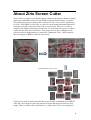
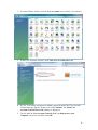
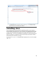
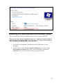
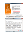
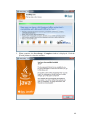
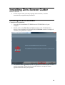
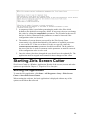
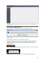
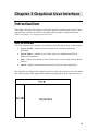
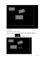
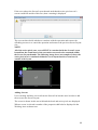
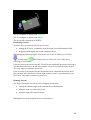
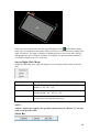
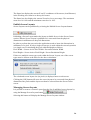
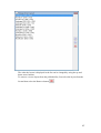
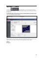
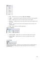
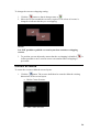
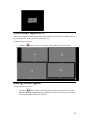
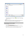
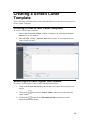
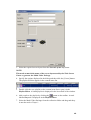
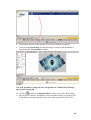
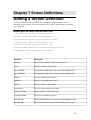
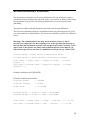
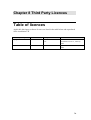
abc
®
Ziris Screen Cutter
Installation and User Manual
Before operating the software, please read this manual
thoroughly and retain it for future reference.
Version 1.00
1st Edition Rev 3
© 2009 Sony United Kingdom Limited
NOTICE TO USERS
Trademark Notice
© 2009 Sony United Kingdom. All rights reserved.
This manual or the software described herein, in whole
or in part, may not be reproduced, translated or reduced
to any machine readable form without prior written
approval from Sony Corporation.
Sony is a registered trademark, and Ziris is a trademark
of Sony Corporation.
Microsoft and Windows are registered trademarks of
Microsoft Corporation in the United States and other
countries.
Other system names, product names and company
names appearing in this manual are trademarks or
registered trademarks of their respective holders. In
this manual such names are not indicated by ® or ™
symbols.
SONY UNITED KINGDOM LIMITED PROVIDES
NO WARRANTY WITH REGARD TO THIS
MANUAL, THE SOFTWARE OR OTHER
INFORMATION CONTAINED HEREIN AND
HEREBY EXPRESSLY DISCLAIMS ANY IMPLIED
WARRANTIES OF MERCHANTABILITY OR
FITNESS FOR ANY PARTICULAR PURPOSE
WITH REGARD TO THIS MANUAL, THE
SOFTWARE OR SUCH OTHER INFORMATION.
IN NO EVENT SHALL SONY CORPORATION BE
LIABLE FOR ANY INCIDENTAL,
CONSEQUENTIAL OR SPECIAL DAMAGES,
WHETHER BASED ON TORT, CONTRACT, OR
OTHERWISE, ARISING OUT OF OR IN
CONNECTION WITH THIS MANUAL, THE
SOFTWARE OR OTHER INFORMATION
CONTAINED HEREIN OR THE USE THEREOF.
Sony United Kingdom reserves the right to make any
modification to this manual or the information
contained herein at any time without notice.
The software described herein may also be governed
by the terms of a separate user license agreement.
Material data used for content creation, such as video,
graphics, and text, may be copyrighted. Unauthorised
distribution and/or playout of such content may be
contrary to the provisions of the copyright laws.
Also, the system allows you to use the fonts installed
on the PC to create test material. Such fonts are
copyrighted. Authorisation is required to use them for
playout.
Chapter 1 Overview....................................................................5
Introduction............................................................................................................... 5
About this manual ................................................................................................. 5
Associated documents........................................................................................... 5
About Ziris Screen Cutter ......................................................................................... 6
Chapter 2 Getting started ............................................................8
Introduction............................................................................................................... 8
PC Requirements .................................................................................................. 8
Preparing your PC for installation ............................................................................ 8
Turn Off User Account Control (UAC)................................................................ 8
Installing Java ......................................................................................................... 10
Installing the Java Runtime Environment (JRE) ................................................ 11
Installing Ziris Screen Cutter .................................................................................. 14
Installing the Ziris software ................................................................................ 14
Optimising Ziris Screen Cutter ............................................................................... 18
Changing the default memory settings ............................................................... 18
Optional configuration ........................................................................................ 18
Starting Ziris Screen Cutter .................................................................................... 19
Starting the application ....................................................................................... 19
Exiting the application ........................................................................................ 20
Uninstalling Ziris Screen Cutter ............................................................................. 21
Chapter 3 Graphical User Interface ..........................................22
Introduction............................................................................................................. 22
GUI Windows ..................................................................................................... 22
GUI Framework ...................................................................................................... 23
Screen Layout ......................................................................................................... 25
Screen Layout Area............................................................................................. 28
Screen Cutter........................................................................................................... 38
Screen Cutter Area.............................................................................................. 40
Jobs ......................................................................................................................... 46
Jobs Area............................................................................................................. 48
About....................................................................................................................... 51
Chapter 4 Using Ziris Screen Cutter.........................................52
Introduction............................................................................................................. 52
Ziris Screen Cutter Workflow................................................................................. 52
Creating a Screen Layout........................................................................................ 53
Creating a new screen layout .............................................................................. 53
Adding screens to the layout............................................................................... 54
Rotating screens .................................................................................................. 55
Changing screen overlaps ................................................................................... 55
Centre screens ..................................................................................................... 56
Trim screen layout to fit...................................................................................... 57
Saving screen layout ........................................................................................... 57
Publishing a screen layout .................................................................................. 58
Creating a Screen Cutter Template ......................................................................... 59
Creating a new screen cutter template ................................................................ 59
Selecting a screen layout and folders.................................................................. 59
Previewing an image sequence ........................................................................... 60
Adjusting in and out points ................................................................................. 60
Defining frame rate, bit-rate and proxy settings ................................................. 61
Saving a screen cutter template........................................................................... 61
Adding a job............................................................................................................ 62
Submitting a screen cutter job............................................................................. 62
Using Watch Folders............................................................................................... 62
Making use of a Watch Folder............................................................................ 64
Monitoring progress................................................................................................ 64
Monitoring the progress of a job......................................................................... 64
Using Multi-Video Packages .................................................................................. 65
Manual Import of Multi-Video Packages ........................................................... 65
Automatic import of Multi-Video Packages....................................................... 66
Using a Multi-Video Package in a playlist ......................................................... 67
Chapter 5 Image Sequences......................................................71
Image Sequence conventions.................................................................................. 71
Chapter 6 Limitations ...............................................................73
Limitations and restrictions..................................................................................... 73
Source folders ..................................................................................................... 73
Use of network drives ......................................................................................... 73
Invalid Screen Layouts ....................................................................................... 73
Chapter 7 Screen Definitions....................................................74
Adding a Screen Definition .................................................................................... 74
Example Screen Definition file........................................................................... 74
Screen Definition Precision ................................................................................ 75
Chapter 8 Third Party Licences ................................................76
Table of licences ..................................................................................................... 76
Chapter 1 Overview
Introduction
About this manual
Readership
This manual is intended for users of the Ziris Canvas product and specifically those
wishing to use the Ziris Screen Cutter application to generate content for use within
Ziris Canvas.
Structure
This manual comprises the following chapters:
Chapter 1: Overview – introduces the Ziris application and describes its main
functions and features.
Chapter 2: Getting started – describes how to install the software and get the Ziris
application up and running.
Chapter 3: Graphical User Interface – describes the window and menu options
provided by the graphical user interface (GUI).
Chapter 4: Using Ziris Screen Cutter – describes the typical operations (workflow)
for using the Ziris application.
Associated documents
The following manuals are available for Ziris Canvas:
Ziris Create: Installation and Reference Manual for Administrator
Ziris Create: Operation and Reference Manual for Authors
Ziris Manage: Installation and User Manual
Ziris Edge: Installation and User Manual
Ziris Canvas Installation and User Manual
5
About Ziris Screen Cutter
Ziris Canvas is a multi-screen digital signage solution supporting an arbitrary number
and layout of full HD screens to create a high resolution virtual canvas. A separate
PS3 running Ziris View is used to drive each screen. Ziris View on PS3 supports up
to 1920 x 1080 MPEG2 video files. A video file can be transformed and rendered in
real-time to stretch it across the Ziris Canvas screen layout. However, in order to
maximise the media resolution on each screen, it is necessary to pre-process content
rendered at the full canvas resolution. This pre-process involves cutting out each
screen area and scaling/rotating as required to a landscape 1920 x 1080 resolution
then encoding as a MPEG2 video for each screen.
Video displayed on each screen
Ziris Screen Cutter is used to perform this pre-processing. In addition to the MPEG2
video files, Ziris Screen Cutter will generate a layout descriptor file and a preview
image. This set of files will be referred to as a "multi-video". Ziris Create supports
6
importing multi-video files and allows them to be manipulated in the playlist editor as
a single high resolution video item.
7
Chapter 2 Getting started
Introduction
This chapter details the personal computer (PC) requirements for installing and
running the Ziris software. It provides step-by-step instructions for preparing and
configuring your PC, for installing the Ziris software and any additional components.
It also describes any post-installation optimisation and adjustments.
PC Requirements
This section describes the minimum requirements of the hardware platform on which
you will install your Ziris software. Please check to ensure your PC meets or exceeds
the requirements detailed below. This is the minimum specification to use the
‘Cutting’ functionality of the Ziris Screen Cutter application. It is possible to use
the ‘Layout’ only feature of the Ziris Screen Cutter application on a lower
specification PC.
Item
Operating
System
CPU
RAM
GPU
HDD
Standard specification
Windows Vista Business Edition SP1 64bit
Intel Xeon 3GHz Quad Core (or faster / more cores / 2
x CPU)
4Gb or greater
1920 x 1080 or greater
At least 40GB for OS + separate HDD for media
depending on requirements (e.g. 300GB)
Preparing your PC for
installation
Turn Off User Account Control (UAC)
Turning off the User Account Control feature is recommended prior to installation of
the software to ensure that the installation process is not interrupted.
To perform the following procedure, you must be able to log on with, or provide the
credentials of, a member of the local Administrators group.
1. Click Start, and then click Control Panel.
8
2. In Control Panel, double-click the User Accounts icon (Classic View shown).
3. In the User Accounts window, click Turn User Account on or off.
4. If UAC is currently configured in Admin Approval Mode, the User Account
Control message appears. In this case click Continue. The Turn User
Account Control On or Off window is displayed.
5. Un-tick the Use User Account Control (UAC) to help protect your
computer check-box and then click OK.
9
6. Click Restart Now to apply the change right away, or click Restart Later
and close the User Accounts tasks window.
Installing Java
The Java Runtime Environment MUST be installed manually on your computer
before installing Ziris Screen Cutter. The Ziris Screen Cutter application is designed
to work on both 32-bit and 64-bit versions of Windows Vista Business Edition. Two
versions of the Java Runtime Environment are provided on the Ziris Screen Cutter
Installation disk – one for use with Windows Vista Business 32-bit Operating System
and one for Windows Vista Business 64-bit. The user must select the Java version
which matches the OS that they are using.
To check the Java version – use Control Panel->System and then check the System
Type value.
10
Installing the Java Runtime Environment (JRE)
The screenshots shown in this example are for the 32-bit version of the JRE.
Ziris Screen Cutter has been qualified with Java ™ Platform Standard Edition
(SE) Runtime Environment (JRE) Version 6 (1.6.0_13). If a previous version of
Java™ is already installed please remove this first.
1. Insert the Ziris installation CD-ROM into the CD-ROM drive of your
computer.
2. Double-click on either jre-6u13-windows-i586-p.exe (for 32-bit) or jre6u13-windows-x64-p.exe (for 64-bit), on the CD-ROM to display the
Welcome screen. Click the [View License Agreement] button.
11
3. The View License Agreement window is displayed. Scroll down the screen
to read the agreement and click the [Close] button to return to the previous
window. Click the [Accept] button to continue the installation.
4. Files are now copied onto the computer.
12
5. When complete, the Java Setup – Complete window is displayed. Click the
[Finish] button to close the window.
13
Installing Ziris Screen Cutter
Before You Start
•
If Ziris Screen Cutter is already running on the machine, it will be
automatically stopped during installation.
Installing the Ziris software
Commence the installation
1. Insert the Ziris installation CD-ROM into the CD-ROM drive of your
computer.
2. Double-click on the Ziris Screen Cutter.exe file on the CD-ROM. Ziris
Screen Cutter installation is launched and the Welcome window is displayed.
Click the [Next] button to continue.
3. The Ziris License Agreement window is displayed. Scroll down the screen to
read the agreement. Select the relevant radio button to accept the license
agreement and click the [Next] button.
14
Checking for Java ™
4. The installer shall check to ensure that the required version of Java JRE has
been installed on this machine. If this is NOT found, the following message
shall be displayed and when the user clicks the [OK] button the installation
shall be automatically aborted.
Choose Destination Location
5. A destination location must now be chosen for the Ziris Screen Cutter
software files on the Choose Destination Location screen. Click the [Next]
button to accept the default location and display the next window.
15
6. The Ready to Install the Program screen is displayed. Click the [Install]
button to continue installation.
7. A progress bar indicates the installation Setup Status.
16
8. When finished, the Installation Wizard Complete window is displayed.
Select whether to restart your computer now or later by clicking the relevant
radio button, then click the [Finish] button to close the window.
17
9. Reboot the PC to ensure the software installation is completed successfully.
Ziris Screen Cutter is now ready to use but performance must now be
optimised, see Optimising Ziris Screen Cutter.
Optimising Ziris Screen Cutter
Changing the default memory settings
The default installation of the Ziris Screen Cutter application shall setup a batch file
to launch the application with a specific amount of memory which defaults to
750MB.
To modify the memory that is available to the application:
1. Browse to the C:\Sony\Ziris Screen Cutter\ directory.
2. Right-click the launch.bat.file and select the Edit option to open the file in a
text editor.
3. Change the value from 950 to a setting that is suitable for your computer. The
Screen Cutter needs enough memory to be able to process the various
images, Memory = Image Width x Image Height * 20. When allocating
memory to the application please ensure that the computer has this
amount of memory available – remembering to leave a suitable quantity
of memory for other applications and the Operating System.
4. Once the value has been changed the user should save the updated file. The
application must be stopped and restarted for these changes to take effect.
Optional configuration
For most installations the default configuration of Ziris Screen Cutter should be
sufficient. However, there are some parameters that users may wish to change. To
modify these parameters:
1. Browse to the C:\Sony\Ziris Screen Cutter\conf directory.
2. Right-click the screencutter.properties.file and select the Edit option to
open the file in a text editor.
18
3. A temporary folder is used when generating the multi-video files which
defaults to the default Java temporary folder. If necessary, the user can change
this value by editing the temp.folder= parameter. The # symbol at the start of
the line is used to comment out the parameter so must be removed if the
configuration value is to be used.
4. The number of screens that are processed by the Ziris Screen Cutter
concurrently is by default determined by the number of available processors
or cores on the PC. If the user wishes to fix this to a specific value the
concurrent.screen.count= parameter should be modified. The # symbol at
the start of the line is used to comment out the parameter so must be removed
if the configuration value is to be used.
5. Once the value(s) has been changed the user should save the updated file. The
application must be stopped and restarted for these changes to take effect.
Starting Ziris Screen Cutter
Ziris Screen Cutter is a Window Application. Details of the screens, menus and other
options are provided in Chapter 3, Graphical User Interface.
Starting the application
To start the Ziris application, click Start > All Programs > Sony > Ziris Screen
Cutter > Start Ziris Screen Cutter.
When starting the software, the basic application is displayed without any of the
options on the Menu Bar selected.
19
To use the application and access the available screens, select the appropriate icon in
the Menu Bar.
Exiting the application
When the user closes the application a message is displayed as follows:
The Ziris Screen Cutter application can run in the background without the actual main
window visible.
Selecting the [Exit] button exits the application completely.
Selecting the [Background] button results in the Ziris Screen Cutter running in the
background. All current jobs shall be processed and Watch Folders shall be
monitored. A Ziris Screen Cutter icon shall be displayed in the Task Tray at the
bottom of the screen.
Once running in Background Mode, right-clicking on the icon in the Task Tray shall
display a context menu:
To display the main application window, select Show Ziris Screen Cutter.
20
To exit the application completely, select Exit Ziris Screen Cutter.
Uninstalling Ziris Screen Cutter
To uninstall the Ziris Screen Cutter software:
1. Select Start > Control Panel and select Programs and Features to display a
list of the programs and utilities installed on your machine.
2. In the list box, select Ziris Screen Cutter, and click the Uninstall button.
3. Follow the instructions on the screen to uninstall the application and click the
[OK] button to confirm. The uninstaller starts and a confirmation dialog box is
displayed when installation is complete.
Notes
•
The above procedure only removes the Ziris software. Java Runtime
Environment can be removed using the same procedure.
•
The above procedure will NOT remove all folders and files associated
with the Ziris software. Delete the Ziris folder manually at
C:\Sony\Ziris Screen Cutter.
21
Chapter 3 Graphical User Interface
Introduction
This chapter describes the windows and menu options provided by the Screen Cutter
graphical user interface (GUI). For operations and procedures using Ziris Screen
Cutter see Chapter 4, Using Ziris Screen Cutter.
GUI Windows
The GUI comprises four windows, described in the following sections of this chapter:
•
Screen Layout – enables Screen Layouts to be created/modified and
published.
•
Screen Cutter – enables Screen Cutter jobs to be submitted and Watch
Folders to be defined.
•
Jobs – enables monitoring of Screen Cutter Jobs and currently defined Watch
Folders.
•
About – displays information about the Ziris Screen Cutter application.
The windows are displayed by using the cursor to select the relevant icon in the Menu
Bar, which results in the appropriate window being displayed in the Operation Area.
22
GUI Framework
The graphical user interface is arranged as follows:
Hide Menu Bar
The Menu Bar can be hidden to maximise screen space. Clicking the Hide Menu Bar
button will collapse the Menu Bar.
Menu Bar
The Menu Bar provides icons/buttons to enable you to select the display in the
Operation area:
Icon
Description
Screen Layout. Enables the creation/modification of screen
layouts. Also allows the screen layouts to be published for
use within the Screen Cutter.
Screen Cutter. Allows the user to create and submit jobs to
be processed by the Screen Cutter application. Also allows
Watch folders to be defined.
Jobs. Allows the user to view the current Screen Cutter jobs
that are either pending, in-progress, completed etc.
About. Displays version and copyright information.
23
Title Bar
The Title Bar at the top of the GUI displays the Sony and Ziris logos.
Operation Area
Provides the work area for users of the Ziris Screen Cutter application. Items shown
in the operation area vary depending on the icon selected in the Menu Bar.
24
Screen Layout
Clicking the
(Screen Layout) icon in the Menu Bar displays
the Screen Layout window. To leave this window, simply select an alternative icon in
the Menu bar.
The Screen Layout window provides the tools to enable a user to create, modify and
publish screen layouts for use within the Screen Cutter application.
When displayed for the first time, some tools and functions will be greyed out or not
displayed, only becoming available when the appropriate action is taken.
Menus
Some menu options, described below, are also available from the Toolbar.
File Menu
25
•
New – enables the user to access the File>New SubMenu
•
Open… – enables the user to open a previously saved Screen Layout.
•
Save – enables the user to save the current Screen Layout.
•
Save As… - enables the user to save the current Screen Layout with a new
name.
•
Refresh Screen List - enables the user to refresh the list of available screen
types.
•
Exit – enables the user to exit the application.
File-New SubMenu
•
Screen Layout – enables the user to create a new empty Screen Layout.
•
Screen Cutter – enables the user to create a new empty Screen Cutter
template.
Layout Menu
•
Manage Screen Layouts – enables the user to manage the list of published
Screen Layouts, including re-ordering the list and removing a Screen Layout
from the Published List.
Toolbar
Enables quick access to many of the Screen Layout functions.
26
Button
Description
New Screen Layout – enables the user to create a new empty Screen
Layout
Open Screen Layout - enables the user to open a previously saved
Screen Layout.
Save Screen Layout - enables the user to save the current Screen
Layout.
Save As Screen Layout - enables the user to save the current Screen
Layout with a new name.
Export Screen Mounting Points – enables the user to export the
Mounting Points for the screens in the current screen layout.
Trim Screen Layout – enables the user to trim the existing screen
layout area so that it only includes the active pixels areas of the screens
in the layout.
Centre Screens – enables the user to centre the current screens within
the existing screen layout area.
Zoom In – enables the user to zoom-in on the screen layout.
Zoom Out – enables the user to zoom-out on the screen layout.
Zoom To Fit – enables the user to change the zoom so that the entire
screen layout fits the available space within the Screen Layout Area.
Allowed/Disallowed Overlapping of Screens – enables the user to
allow/disallow overlapping of screens in the screen layout. This icon
shall be changed to
if screen overlapping is disallowed.
27
Screen Layout Area
This is the main area where you can drag-and-drop screens, move screens and rotate
screens to create the desired screen layout.
NOTE:
All positions and coordinates in the Screen Layout Area are given in millimetres
and are intended to match the physical positions of the screens.
Screen Layout
This area displays the properties of the currently open Screen Layout.
•
Title – displays the name of the currently open Screen Layout. If the Screen
Layout has not been saved this shall be blank and an * shall be displayed
next to the Screen Layout group box.
28
•
Width (mm) – displays the width of the Screen Layout in millimetres. This
field can be edited by the user.
•
Height (mm) – displays the height of the Screen Layout in millimetres. This
field can be edited by the user.
Selected Screen Information
When the user selects a screen in the Working Area, the properties of this screen shall
be displayed in the Selected Screen Information.
•
Screen ID – a unique ID that is used to identify the screen within the overall
screen layout. This shall be used by the Screen Cutter and also within Ziris
Create and Ziris Manage so that the Ziris View PS3 device knows what
section of content to play out. This field can be edited. If a Screen ID is
entered that is already in use, a warning message will be displayed and a new
Screen ID must be provided.
•
Category – the type of screen derived from the Available Screens (currently
either LCD or Flat Panel). This field can NOT be edited.
•
Model – this is the model of the chosen screen, e.g. FWD-40LX2, FWDS47H1. The Model can NOT be edited.
•
X (mm) – this is the X coordinate (in millimetres) of the top left hand corner
of the selected screen relative to the screen layout. This value can be edited.
The user will be warned if they attempt to set the coordinate such that the
screen would be outside the screen layout bounds.
•
Y (mm) – this is the Y coordinate (in millimetres) of the top left hand corner
of the selected screen relative to the screen layout. This value can be edited.
The user will be warned if they attempt to set the coordinate such that the
screen would be outside the screen layout bounds.
29
•
Rotation – this is the rotation of the top-left hand corner of the screen from
the standard landscape position.
The user shall be able to edit this value within the range 0-360°.
•
Width – this is the width of the screen in millimetres. This field can NOT be
edited.
30
•
Height – this shall be the height of the screen in millimetres. This field can
NOT be edited.
Available Screens
All of the available screens shall be displayed in the Screens list.
This Screens List is automatically generated from Screen Definition files (XML files)
that are stored in the following folder: C:\Sony\Ziris Screen Cutter\conf\screens.
Please refer to Chapter 7: Screen Definitions on page 74 for more details on adding
screen definitions.
Each Screen Definition file contains information relating to the physical dimensions
of the screen. It also contains details of the screen Category and Model.
Each Category is displayed as a separate group in the tree structure. In the above
example, only the LCD category is defined.
If additional screen definition files are added into the appropriate folder, the user can
refresh the Screen List by selecting the Refresh button
.
The user can drag-and-drop screens from this area into the Working Area.
Working Area
This is the area in which the user defines the actual Screen Layout.
31
The actual Screen Layout bounds are displayed by the white box around the screens
as shown above.
Changing the Screen Layout Size
The user can change the Screen Layout bounds by either editing the Width and
Height as described previously or by selecting the bottom right hand corner of the
Screen Layout bounds
and dragging to the desired size.
32
If the user reduces the Screen Layout bounds such that the active pixel area of a
screen would fall outside of this area, then a warning is displayed.
The user can then decide whether to continue with the operation and remove the
offending screens or to cancel the operation and return to the previous Screen Layout
size.
NOTE:
All of the active pixels on a screen MUST be contained with the Screen Layout
bounds but the actual bezel of the screen does not need to be contained within
the Screen Layout bounds. The following image shows an example of where the
active pixel area is contained within the screen layout but the screen bezel is
outside of the layout.
Adding Screens
Users can drag-and-drop a screen from the Screen List into this area in order to add
the screen to the Screen Layout.
The screen is shown in this area with both the bezel and active pixel area displayed.
When a screen is selected a number of the properties shall also be displayed in the
Working Area as shown next.
33
The X-coordinate is displayed in GREEN.
The Y-coordinate is displayed in BLUE.
The Screen ID is displayed in WHITE.
Positioning Screens
Screens can be re-positioned in one of two ways:
•
editing the X and Y coordinates in the Selected Screen Information fields
•
dragging and dropping the screens using the mouse
When dragging and dropping the screens the user is able to make use of vertical
and horizontal
movement arrows to ensure the screen only moves
vertically or horizontally.
If the user moves the mouse onto the Vertical Arrow and holds the mouse down, they
can then move the mouse up and down and the screen is re-positioned only on the Y
axis. Any angle of rotation is preserved.
If the user moves the mouse onto the Horizontal Arrow and holds the mouse down,
they can then move the mouse left and right and the screen is re-positioned only on
the X axis. Any angle of rotation is preserved.
Rotating Screens
The angle of rotation of a screen can be changed several ways:
•
editing the rotation angle in the Selected Screen Information
•
using the mouse to rotate the screen
•
using the right-click context menu
Rotating the screen by using the mouse is shown next.
34
If the user moves the mouse onto the Green Rotation Circle
and holds the mouse
down, they can then move the mouse either clockwise or anti-clockwise to change the
angle of rotation. The angle of rotation is displayed next to the screen and is always
calculated based on a clockwise rotation, for example, an anti-clockwise rotation of
30° shall be displayed as 330° clockwise.
Screen Right-Click Menu
Within the Working Area, right-clicking on a screen will provide a menu as shown
next.
Command
Description
Rotate To
Rotates the screen to a specific angle – the available options
include 0°, 45°, 90°, 315°.
Rotate
Rotates the screen by a specific amount – the available
options include -90°, -45°, 45°, 90°.
Delete
Deletes the screen from the Screen Layout (screens can also
be deleted by selecting the Delete key.
NOTE:
“Rotate” adjusts the angle by the specified amount whereas “Rotate To” sets the
angle to the specific value.
Status Bar
35
The Status bar displays the current X and Y coordinates of the mouse (in millimeters)
in the Working Area relative to the top left corner.
The Status bar also displays the current Zoom level as a percentage. The maximum
zoom level is 100% and the minimum zoom level is 10%.
Publish Screen Layouts
Screen Layouts can be published by selecting the Publish Screen Layouts button:
.
Publishing a Screen Layout makes the layout available for use in the Screen Cutter
section. When a Screen Layout is published it is converted from the physical
dimensions in millimeters to the pixel dimensions.
In order to perform the conversion the application needs to know the dimensions in
millimeters of a pixel. If only a single screen type is used within the screen layout this
is a simple case of calculating the pixel width and height as follows:
Pixel Width = Screen Active Pixel Width / Screen Resolution Width
Pixel Height = Screen Active Pixel Height / Screen Resolution Height
If there are multiple screen types used within the Screen Layout, one of the screen
types must be chosen as the basis for the above calculation.
The calculated screen layout size (in pixels) is displayed next to each screen.
Clicking the [OK] button will cause the screen layout to be converted from physical
dimensions into pixels and the layout can then be selected from the Screen Cutter
screen.
Managing Screen Layouts
It is possible to remove a Screen Layout from the list of published screen layouts by
using the Manage Screen Layouts button
.
Selecting this button will display the Manage Screen Layouts window.
36
The order the layout is displayed in the list can be changed by using the up and
down arrow buttons.
To remove a screen layout from the published list, first select the layout from the
list and then select the Remove button:
.
37
Screen Cutter
Clicking the
(Screen Cutter) icon in the Menu Bar displays
the Screen Cutter window. To leave this window, simply select an alternative icon in
the Menu bar.
The Screen Cutter window allows the user to create and submit jobs to be processed
by the Screen Cutter application and also allows Watch folders to be defined, so that
jobs can be submitted using hot-folders.
When displayed for the first time, some tools and functions will be greyed out or not
displayed, only becoming available when the appropriate action is taken.
Menus
File Menu
38
•
New – enables the user to access the File>New SubMenu
•
Open… – enables the user to open a previously saved Screen Cutter template.
•
Save – enables the user to save the current Screen Cutter template.
•
Save As… - enables the user to save the current Screen Cutter template with a
new name.
•
Revert – reverts the current Screen Cutter template to the previously saved
configuration.
•
Exit – enables the user to exit the application.
File-New SubMenu
•
Screen Layout – enables the user to create a new empty Screen Layout.
•
Screen Cutter – enables the user to create a new empty Screen Cutter
template.
Layout Menu
Manage Screen Layouts – enables the user to manage the list of published Screen
Layouts, including re-ordering the list and removing a Screen Layout from the
Published List.
39
Screen Cutter Area
This is the main area where the user can create Screen Cutter jobs and add Watch
Folders.
Screen Cutter
This section allows the user to choose from the list of Published Screen Layouts that
may have been created using the Screen Layout section of the application and to
define the Source and Destination Folders.
•
Screen Layout – defines the Screen Layout to be used when performing the
cutting operation. The user can select the layout from the drop-down list. The
Manage Published Layouts window can also be accessed from the Manage
Published Layouts button
.
40
•
Source Folder – defines the folder containing the image sequence(s) to be
processed. The folder can be changed by selecting the Browse button
and then choosing a source folder.
•
Destination Folder – defines the folder to which the Multi-Video Package
shall be output. The folder can be changed by selecting the Browse button
and then choosing a destination folder.
•
Add Job(s) – allows the user to add a job for the currently defined Screen
Cutter template to the Job List. All output videos MUST be at least 2
seconds in duration.
•
Add to Watch List – allows the user to add the currently defined Screen
Cutter template to the Watch List.
Preview
This section allows the user to preview the selected image sequence and to configure
items such as the Thumbnail. The main area of the Preview Window displays the
selected Screen Layout Mask.
If the selected Source Folder contains more than one image sequence, each image
sequence can be selected from a drop-down list.
41
When an image sequence is selected the first image of the sequence is loaded into the
Preview Window with the Screen Layout mask.
The currently selected frame and the total number of frames in the image sequence is
displayed in the Preview Section.
Preview Toolbar
The main preview functionality can be accessed from the preview toolbar.
Adjust in/out-point toggle
The in and out points within the image sequence can be adjusted in order to generate
the video files from only a section of the image sequence. By default the in and out
points cannot be adjusted as the toggle shall be in the “use-full sequence” option
. When in this state, the Mark In, Mark Out, Adjust In-Point and Adjust OutPoint options are disabled.
Select the toggle to change the state. When in the “adjust in-out points” state:
,
the Mark In, Mark Out, Adjust In-Point and Adjust Out-Point options are enabled.
Mark-In
Selecting the mark-in button
, shall select the image currently displayed in the
preview window as the new in-point. This allows the user to only generate video clips
from a specified section of the image sequence.
Adjust In-Point (image number)
The In-Point can also be adjusted by entering a value in the edit field
or using the up-down arrows to change the value.
The in-point must always be before the out-point. If the user selects the Mark-In
button this value shall be automatically updated to reflect the new in-point.
42
Step Back
Select the Step Back button
Preview Window.
to display the previous image in the sequence in the
Preview Slider
The preview slider can be used to move within the image sequence.
The selected image within the sequence is loaded into main preview window as the
user moves within the sequence.
NOTE:
It can take a few seconds to load the full resolution image into the preview
window. The Screen Cutter shall initially load a low-resolution copy of the image
into the preview window which shall then be updated once the full resolution
image has been loaded into memory.
Step Forward a Frame
Select the Step Back button
Preview Window.
to display the next image in the sequence in the
Mark-Out
Selecting the mark-out button , shall select the image currently displayed in the
preview window as the new out-point. This allows the user to only generate video
clips up to a specified section of the image sequence.
Adjust Out-Point (image number)
The Out-Point can also be adjusted by entering a value in the edit field
or using the up-down arrows to change the value.
The out-point must always be after the in-point. If the user selects the Mark-Out
button this value shall be automatically updated to reflect the new out-point.
Revert to full sequence
Changing the Adjust in/out-point toggle to the “use-full sequence” option
results in the in and out points being automatically adjusted to cover the whole image
sequence.
Zoom
Three buttons are provided to change the zoom level.
43
Selecting the Zoom In button
window zoom-level.
Selecting the Zoom to fit button
Window fills the available space.
or the Zoom Out button
adjusts the preview
changes the zoom level so that the Preview
Thumbnail
A thumbnail can be generated from any of the images in the image sequence. The
thumbnail is included as part of the multi-video package and is used in the Ziris
Create Collection View. The image to be used as the thumbnail can be changed either
by editing the value in the edit field or using the up-down arrows.
The image currently selected in the Preview Window can be selected as the thumbnail
image by selecting the Use as thumbnail button
.
Create Proxy Video
Selecting the Create Proxy Video button adds a job to the Screen Cutter job list to
create a proxy video for the currently configured Screen Cutter template.
Save Preview Image
Selecting the Save Preview Image button saves the current preview image with the
screen layout overlay.
Create Mask
Selecting the Create Mask button creates an image with a transparent rectangle for
each screen.
Create Calibration
Selecting the Create Calibration button creates a calibration image that can be used to
determine if this layout matches the physical layout.
Configuration
This section allows the user to configure the various parameters used when generating
the video clips and proxy clip.
44
•
Frame Rate – defines the frame rate to be used when encoding the image
sequence into video clips. The user is able to select from 23.98, 24, 25, 29.97
and 30.
•
Input Timeout (s) – defines the time (in seconds) that the Screen Cutter shall
wait after reading the last image in the sequence in the specified source folder,
before completing the job. Jobs can be started whilst the images are still
being copied to the Source Folder. This timeout allows for delays when
writing files to this folder.
•
Average Bit Rate (Mbps) - defines the average bit-rate in Mbps to be used
when encoding the image sequence into video clips. This value ranges from 5
to 51 Mbps. The Maximum Bit Rate MUST always be greater than or
equal to the Average Bit Rate and so the Maximum Bit Rate is
automatically adjusted if increasing the Average Bit Rate would break
this rule.
•
Maximum Bit Rate (Mbps) - defines the maximum bit-rate in Mbps to be
used when encoding the image sequence into video clips. This value ranges
from 5 to 51 Mbps. The Maximum Bit Rate MUST always be greater than
or equal to the Average Bit Rate and so the Average Bit Rate is
automatically adjusted if decreasing the Maximum Bit Rate would break
this rule.
•
Include Proxy Video in Multi-Video file – specifies whether a proxy video
should be generated and included in the Multi-Video package.
•
Proxy Width – defines the width of the proxy video file in pixels. The user
can select from the following range of values: 320, 640, 960, 1280, 1600,
1920.
•
Proxy Height – defines the height of the proxy video file in pixels. The user
can select from the following range of values: 180, 360, 540, 720, 900, 1080.
•
Proxy Bit Rate (Mbps) – defines the bit-rate in Mbps to be used when
encoding the image sequence into a proxy video clip. This value ranges from
1 to 51 Mbps.
Status Bar
This section displays the current Zoom level and any other status/warning messages.
45
Jobs
Clicking the
(Jobs) icon in the Menu Bar displays the Jobs
window. To leave this window, simply select an alternative icon in the Menu bar.
The Jobs Window allows the user to view the current Screen Cutter jobs that are
either pending, in-progress, completed etc.
When displayed for the first time, some tools and functions will be greyed out or not
displayed, only becoming available when the appropriate action is taken.
Menus
File Menu
•
New – enables the user to access the File>New SubMenu
46
•
Open… – enables the user to open a previously saved Screen Cutter template.
•
Exit – enables the user to exit the application.
File-New SubMenu
•
Screen Layout – enables the user to create a new empty Screen Layout.
•
Screen Cutter – enables the user to create a new empty Screen Cutter
template.
Layout Menu
Manage Screen Layouts – enables the user to manage the list of published Screen
Layouts, including re-ordering the list and removing a Screen Layout from the
Published List.
47
Jobs Area
This is the main area in which jobs can be monitored and even cancelled if required.
It is also the area in which the currently configured Watch Folders can be viewed and
if necessary removed from the configured Watch Folders list.
Jobs Tab
The jobs tab displays the jobs that are currently in one of the following states:
•
Pending
48
•
In Progress
•
Completed
•
Failed
•
Aborted
Job Filters
The job filters section of the Jobs Tab enables you to filter the information displayed
in the jobs list in order to display jobs that are of a specific state.
If a filter is ticked
shall be enabled.
then jobs of that state shall be displayed. By default all filters
Job List
The job list displays a list of all of the Screen Cutter jobs. Each row in the list refers
to a specific job.
The Jobs List displays the following fields for each job:
•
Description – a description of the cutting job, normally the first item in the
image sequence and the name of the layout being used.
•
Progress Bar – a bar to indicate the progress of the job. This shall be
coloured as follows:
o Yellow – job in progress
o Green – completed successfully
o Red – job failed
o Grey – job aborted
•
Message – message indicating current phase of the job or any error message
that may have been generated.
•
Created – this is the time and date that the job was created/submitted.
Cancel Jobs
Selecting the Cancel Jobs button cancels any pending or in-progress jobs that are
currently selected in the Job List.
Clear Jobs
Selecting the Clear Jobs button clears any failed, aborted or completed jobs that are
currently selected in the Job List.
Watch Folders Tab
49
The Watch Folders Tab displays a list of all of the folders that have been setup to be
monitored for incoming image sequences.
The Watch Folders List displays the following information:
•
Screen Layout – the name of the screen layout to be used when processing
image sequences found in the Watch Folder.
•
Watch Folder – the Source Folder that is being monitored for incoming
image sequences.
•
Output Folder – the Destination Folder to which the Multi-Video packages
shall be written.
Remove from Watch List
Selecting the Remove from Watch List button removes any of the items currently
selected in the Watch List.
50
About
Clicking the
(About) icon in the Menu Bar displays the About
window. To leave this window, simply select an alternative icon in the Menu bar.
This window displays the software version and copyright information for the Ziris
application.
Version Information
The Ziris software version number, build time and date are displayed at the top of the
page.
Java Version
The installed Java version and the recommended Java version are displayed.
Plugin Information
The various plugins that form the Ziris software application are displayed.
51
Chapter 4 Using Ziris Screen Cutter
Introduction
This chapter describes the typical operations and procedures for using and
configuring Ziris Screen Cutter.
A description of all GUI windows and menu options is provided in Chapter 3
“Graphical User Interface” on page 22.
It is impractical to provide instructions for every conceivable configuration and
operation variant. The information provided here, therefore, describes general
procedures for performing typical operations.
Ziris Screen Cutter Workflow
The following figure summarizes the typical workflow when using Ziris Screen
Cutter. It also shows the interaction between Ziris Screen Cutter and Ziris Create to
show how the output of Ziris Screen Cutter is then used in a Ziris Canvas system.
52
Using Ziris Screen Cutter
Screen Layout
Creating a Screen Layout
Creating a new screen layout
Adding screens to the layout
Rotating screens
Changing screen overlaps
Centre screens
Trim screen layout to fit
Saving a screen layout
Publishing a screen layout
Screen Cutter
Creating a Screen Cutter Template
Creating a new screen cutter template
Selecting a screen layout and folders
Previewing an image sequence
Adjusting in and out points
Defining frame rate, bit-rate and proxy settings
Saving a screen cutter template
Screen Cutter
Screen Cutter
Adding a job
Using Watch Folders
Submitting a screen cutter job
Adding a Watch Folder
Making use of a Watch Folder
Jobs
Monitoring progress
Monitoring the progress of a job
Ziris Create
Using Multi-Video Packages
Manual Import of Multi-Video Packages
Automatic Import of Multi-Video Packages
Using a Multi-Video Package in a playlsit
Creating a Screen Layout
There are many possible screen layouts that can be created using Ziris Screen Cutter.
This section describes the creation of a specific layout that is then used in the
remaining workflow sections.
Creating a new screen layout
To create a new screen layout:
1. Ensure that the Screen Layout window is displayed by clicking the Screen
Layout icon in the sidebar.
53
2. Click the
button on the toolbar to display the New Screen Layout dialog
or select the File > New > Screen Layout menu option.
3. Specify the width and height for the screen layout. For this example, leave at
the default values and select the [OK] button.
4. The Screen Layout window shall now display an empty layout of the specified
dimensions.
Adding screens to the layout
To add screens to the layout:
1. Find the required screen in the list of available screens.
2. Drag and drop the required screen type from the Available Screens in the
Screen Layout Working Area.
54
Rotating screens
To rotate a screen in the layout:
1. Highlight the screen to rotate by clicking on it.
2. The screen can be rotated in one of three ways:
a. Change the rotation value in the Selected Screen Information.
b. Right-click on the screen and select an angle or adjustment from the
Rotate To or Rotate menu options.
c. Click on the Green Rotation Circle , and whilst holding the mouse
button down, move the mouse either clockwise or anti-clockwise to
change the angle of rotation.
Changing screen overlaps
When moving screens around the screen layout it can help if the screens are allowed
to overlap.
55
To change the screen overlapping setting:
1. Click the
button so that it changes state to
.
2. Move the screens around the screen as required. The colour of screens is
changed to indicate that they are overlapping.
NOTE:
It is NOT possible to publish a screen layout that contains overlapping
screens.
3. To position screens adjacently ensure that the overlapping is disabled:
is then possible to move screens next to one another and overlapping is
prevented.
. It
Centre screens
To centre the screens within the screen layout:
1. Click the
button. The screens shall then be centred within the existing
dimensions of the screen layout.
a. Before Centre Screens:
b. After Centre Screens:
56
Trim screen layout to fit
If the screen layout is much larger than required then it is possible to trim the layout
to just include the active pixel area of the screens.
To trim the screen layout:
1. Click the
button. The screen layout is then reduced as shown next.
Saving screen layout
To save the screen layout:
1. Click the
button. If this screen layout has not been previously saved the
Save As: Screen Layout dialog is displayed. Select a directory, enter a name
for the screen layout and select [Save].
57
2. The screen layout is then saved as an XML file in the specified directory. It
can be opened at any time by clicking on
> Open menu option.
on the toolbar or using the File
NOTE:
The screen layout is just saved so that it can be accessed at a later date. To
make use of a screen layout it is necessary to publish the layout.
Publishing a screen layout
A saved screen layout:
1. Click the
button to make the current screen
layout available for use in the Screen Cutter window.
2. If more than once screen type is used in the screen layout, choose the screen
type to use as the basis for the conversion from millimetres to pixels.
58
Creating a Screen Cutter
Template
Once a Screen Layout has been created and published it can then be used as part of a
Screen Cutter Template.
Creating a new screen cutter template
To create a screen cutter template:
1. Ensure that the Screen Cutter window is displayed by clicking the Screen
Cutter icon in the sidebar.
2. Select the File > New > Screen Cutter menu option. A new empty Screen
Cutter is then created.
Selecting a screen layout and folders
To select a screen layout, source folder and destination folder:
1. Click on the Screen Layout drop-down menu and select the required screen
layout.
2. Click on the
source folder.
button for the Source Folder and browse to the required
3. Click on the
button for the Destination Folder and browse to the
required destination folder.
59
NOTE:
Please ensure that the PC user account that is running Ziris Screen Cutter
has READ and WRITE access to the configured Source Folder.
Previewing an image sequence
To preview an image sequence:
1. If the Source Folder contains an image sequence(s), the first image sequence
is displayed in the Sequence drop down list.
2. Select an image to preview by using the Preview Slider, or the
and
buttons. The selected image is displayed in the Preview Window for the
previously defined screen layout.
Adjusting in and out points
To adjust the in and out points for an image sequence:
1. Click on the
button so that it changes state to
.
60
2. Adjust the in point by selecting the desired frame and clicking on the
button or enter a new value directly in the
field.
3. Adjust the out point by clicking the selecting the desired frame and clicking
on the
button or enter a new value directly in the
field.
Defining frame rate, bit-rate and proxy settings
To define the frame rate, bit-rate and proxy settings for this Screen Cutter template:
1. Select the required frame rate from the Frame Rate drop down menu.
2. Select the required average bit-rate by using the Average Bit Rate up/down
arrows or entering a value in the field.
3. Select the required maximum bit-rate by using the Maximum Bit Rate
up/down arrows or entering a value in the field.
4. Click on the Include Proxy Video in Multi-Video file option so that it is
ticked.
5. Select the required proxy width by using the Proxy Width up/down arrows or
entering a value in the field.
6. Select the required proxy height by using the Proxy Height up/down arrows
or entering a value in the field.
7. Select the required proxy bit-rate by using the Proxy Bit Rate up/down
arrows or entering a value in the field.
Saving a screen cutter template
Once the screen cutter template has been defined it should be saved for future use.
The last saved screen cutter template is loaded automatically when the Ziris Screen
Cutter application is started and the Screen Cutter window is selected.
To save a screen cutter template:
1. Click the File > Save As menu option. The Save Screen Cutter Template
dialog is then displayed.
2. Select a folder, enter a name and click on the [Save] button.
61
The Screen Cutter template is saved as an XML and can be opened at any time
using the File > Open menu option.
Adding a job
Once a screen cutter template has been configured a job can be submitted to the
Screen Cutter for processing.
Submitting a screen cutter job
To submit a screen cutter job:
1. Configure all of the parameters as defined in Creating a Screen Cutter
Template on page 59 or load an existing screen cutter template.
2. Click on the
button. The job is added to the Jobs List and a
confirmation message is displayed. The job can then be monitored, see
Monitoring progress on page 64.
NOTE:
All output videos MUST be at least 2 seconds in duration. If the configured
template does not include at least 2 seconds of video a warning shall be
displayed and the job will NOT be added.
Using Watch Folders
The Ziris Screen Cutter allows the user to configure watch folders that the application
shall monitor for incoming image-sequences. A screen cutter template is associated
62
with the watch folder so the application knows how to process the incoming image
sequence, for example what screen layout to apply and what bit-rates to use.
To create a watch folder:
1. Create a Screen Cutter template using the steps outlined in the section
Creating a Screen Cutter Template on page 59.
2. When configuring the Source Folder, select a folder that is to be used as the
watch folder. In this case the folder may not contain an image sequence.
3. If the watch folder does not currently contain an image sequence then the
preview functions shall be disabled.
4. Ensure that the Input Timeout (s) is set to at least 5 seconds.
NOTE:
Since this is a Watch Folder a job can be started whilst the images are still
being copied to the Source Folder. This timeout allows for delays when
writing files to this folder. Ziris Screen Cutter shall always wait for this Input
Timeout period after the last image has been copied into the folder before
finishing the job.
5. Click the
button and the Screen Cutter configuration is
added to the Watch Folders. A confirmation message is displayed.
63
6. When the watch folder is added to the Watch Folders list, a process folder is
created in the configured Source Folder. When an image sequence is copied
into the Source Folder it is moved into the process folder before it is
processed.
Making use of a Watch Folder
To make use of the Watch Folder:
1. Copy the required image sequence into the specified Source Folder; see
Chapter 5: Image Sequences for details on how to name an image sequence.
2. When the image sequence is detected a job is added to the Jobs List. The job
can then be monitored, see Monitoring progress on page 64.
3. The image sequence is then moved into a process folder from where the job is
processed.
NOTE:
The images sequences are NOT automatically deleted from the process folder
when the job is completed. The user must manually delete the images if
required.
NOTE:
All output videos MUST be at least 2 seconds in duration. If the image
sequence in the watch folder does not include at least 2 seconds of video the
job will be failed.
Monitoring progress
The Jobs window can be used to monitor the progress of the Ziris Screen Cutter jobs.
Monitoring the progress of a job
To monitor the progress of a job:
1. Ensure that the Jobs window is displayed by clicking the Jobs icon in the
sidebar.
2. The jobs shall be displayed according to the current filter settings. Use the job
filter settings to change which jobs are displayed.
3. Jobs can be removed manually from the list using the
button.
64
Using Multi-Video Packages
The output from Ziris Screen Cutter is a Multi-Video Package that has the file
extension “.mtv”. This file contains the following items:
•
Screen Layout definition file
•
An individual video clip for each of the screens in the layout.
•
Thumbnail image for use in the Ziris Create Collection View.
•
Preview Image for use in the Ziris Create Layout Editor.
The Multi-Video Package can be imported into Ziris Create either manually or
automatically.
NOTE:
When the Multi-Video Package is imported into Ziris Create, the screen layout
is added to the list of available screen layouts already defined in Ziris Create. If
the name of the screen layout in the Multi-Video Package already exists in Ziris
Create, the existing entry in Ziris Create shall be overwritten by the new screen
layout.
Manual Import of Multi-Video Packages
Multi-Video Packages can be manually imported into Ziris Create.
To manually import a Multi-Video Package into Ziris Create:
1. Login to Ziris Create using an author account.
2. Ensure that the Media window is displayed by clicking the Media icon in the
sidebar.
65
3. Click the folder into which you want to import, then select the File > Import
button on the toolbar). The Import
Content menu option (or click the
Content into Ziris Create dialog box is displayed.
4. Specify, or browse to locate, the desired Multi-Video Package. Filter the type
of files displayed by setting Ziris Multi-Video Files in the Files of type: drop
down menu at the bottom of the dialog.
5. With your chosen file selected, click the [Import] button to upload the content
to your Ziris Create collection. A progress dialog is displayed. If the import is
successful the Multi-Video Package will be visible in the content items list.
The image that was selected as the thumbnail in the Ziris Screen Cutter is
displayed in the content items list.
Automatic import of Multi-Video Packages
‘Hot folders’ provide a quick way of importing material into Ziris Create and are
ONLY available from the Ziris Create server.
Ziris Create provides a specific ‘hot folder’ for use with Multi-Video Packages which
can be found in C:\Sony\Ziris Create\ingest\Ziris Multi-Video\.
There is a sub-folder for each different user account but for the purposes of this
example, the default author account shall be used. This means the ‘hot folder’ is
C:\Sony\Ziris Create\ingest\Ziris Multi-Video\author.
To import a Multi-Video Package automatically:
66
1. Copy the required Multi-Video Package (mtv file) to the C:\Sony\Ziris
Create\ingest\Ziris Multi-Video\author folder.
TIP:
It is also possible to define the Ziris Create ‘hot folder’ as the Destination
Folder within a Ziris Screen Cutter template. This means that the MultiVideo Package is automatically imported into Ziris Create as soon as it has
been generated by the Ziris Screen Cutter application.
2. When the Multi-Video Package has been successfully imported it can be
found in the collection: \ziris\Ingested files\ziris multi-video.
Using a Multi-Video Package in a playlist
Once a Multi-Video Package has been imported into Ziris Create it can be added to a
playlist as a single content item.
To add a multi-video package to a playlist:
1. Click the collection folder you want the new playlist to appear in.
2. Select the
button or the File > New Playlist menu option to display the
New playlist dialog.
67
3. Select the required screen layout from the Screen Layout drop down.
NOTE:
This needs to match the name of the screen layout used by the Ziris Screen
Cutter to generate the Multi-Video Package.
4. Specify the options displayed in the dialog and then click the [Create] button.
The playlist will then appear in the content items list.
5. Double-click the new playlist on the content items list to open it in the
Playlist Editor. A blank playlist is displayed in the lower half of the window.
6. Add a track to the playlist by clicking the
button on the toolbar. A track
labelled Layer 1 is displayed in the Playlist Editor.
7. Select the Multi-Video Package from the collection folder and drag-and-drop
it onto the track of Layer 1.
68
8. The position and size in the timeline can now be modified as required.
9. Click on the Layout Editor tab and the image selected for the thumbnail is
displayed in the Layout Editor window.
NOTE:
It is NOT possible to change the size and position of a Multi-Video Package
that is part of a playlist.
10. Click the
button on the Playlist Editor toolbar to save the edited playlist.
11. The playlist can then be scheduled or used as default content as required. Ziris
Create shall send each individual video clip to the required Ziris View PS3.
69
70
Chapter 5 Image Sequences
Image Sequence conventions
It is important to follow a strict naming convention when defining an image sequence.
Each image sequence MUST be numbered so that the Ziris Screen Cutter can
determine the sequence with which to process the images, i.e. the frame order. The
image files MUST contain a zero padded sequence number to define the frame order.
The image sequence file names MUST be identical except for the sequence number.
For example:
image_0001.png
image_0002.png
...
The sequence number MUST be the last digits in the file name.
For example, the following file names will NOT be supported:
image_0001_v1.png
image_0002_v1.png
The following file names should be used instead:
image_v1_0001.png
image_v1_0002.png
Each image sequence should be of the same type. For example, JPEG or BMP. The
following files would be defined as different sequences:
image_v1_0001.png
image_v1_0002.jpg
It is possible to have more than one image sequence in the same Source Folder. The
Screen Cutter shall process each image sequence as a separate job. For example:
Clip1_0001.png
Clip1_0002.png
Clip1_0003.png
Promo1_0001.jpg
71
Promo1_0002.jpg
Promo1_0003.jpg
Each image sequence would be applied to the defined Screen Layout to produce two
different multi-video packages for use in Ziris Create.
An image sequence name can only contain the following characters:
A-Z, a-z, 0-9, ‘_’ (underscore), ‘-‘ (dash) ‘(‘, ‘)’, and ‘.’
If an image sequence contains any other characters they shall be automatically
replaced by ‘_’ (underscore).
72
Chapter 6 Limitations
Limitations and restrictions
This section describes any known restrictions when using the application. For a list of
all current issues please refer to the release notes.
Source folders
The Ziris Screen Cutter application requires READ and WRITE access to the Source
Folder in order to function correctly.
Use of network drives
It is possible to use mapped network drives as the Destination Folder for Screen
Cutter jobs. However, it is NOT possible to use mapped network drives as the Source
Folder for Screen Cutter.
The user is advised to copy the contents network drive onto a local drive on the
Screen Cutter PC.
Invalid Screen Layouts
When the Ziris Screen Cutter application starts the published screen layouts are
loaded from the screenlayouts.xml file. When this is loaded, each screen layout could
potentially be invalid for various reasons including:
1. Missing screen definitions
2. Invalid screen layout name
3. Screen area outside of layout boundary
4. 4. Layout size too big to process (insufficient memory).
Under normal circumstances, it will not be possible to publish an invalid layout to
this file. However, this file may be edited in a text editor or the memory settings may
have been changed since the layout was published. Ziris Screen Cutter will only load
valid screen layouts, invalid screen layouts will not be available via the GUI and will
be removed from the screenlayouts.xml file. To avoid loosing the invalid data
completely, an invalid screenlayouts.xml file will be renamed to
screenlayouts_invalid_yyyyMMdd_HHmm.xml (where yyyyMMdd_HHmm is the
current date and time) before saving a new screenlayouts.xml with only valid layouts.
73
Chapter 7 Screen Definitions
Adding a Screen Definition
A Screen Definition file is an XML file containing various attributes about a
particular screen model. A Screen Definition file can be created using a text editor
(e.g. Notepad)
Example Screen Definition file
<?xml version="1.0" encoding="UTF-8"?>
<Screen category="LCD" name="MyModel"
physicalWidth="1082" physicalHeight="627"
leftInset="21.16" rightInset="21.16"
topInset="21.09" bottomInset="21.09"
resolutionWidth="1920" resolutionHeight="1080"
mountWidth="400" mountHeight="400"/>
Attribute
Description
category
Specifies the category within the Screen List.
name
Specifies a unique model name.
physicalWidth
The physical width (mm) of the panel (including bezel).
physicalHeight
The physical height (mm) of the panel (including bezel).
leftInset
The size of the left bezel (mm).
rightInset
The size of the right bezel (mm).
topInset
The size of the top bezel (mm).
bottomInset
The size of the bottom bezel (mm).
resolutionWidth
The horizontal resolution (pixels)
resolutionHeight
The vertical resolution (pixels)
mountWidth
The horizontal distance between the mounting holes (mm)
mountHeight
The vertical distance between the mounting holes (mm)
74
Screen Definition Precision
The information required to create a screen definition file can usually be found or
calculated from the technical specification. Some care needs to be taken as this affects
the calculation of the picture size and pixel dimensions of a screen layout when
publishing.
The physical width and height should be specified to the nearest millimeter.
The bezel sizes should normally be calculated from the specified physical size, pixel
size and resolution as defined below. The bezel sizes should be specified to 2 decimal
places.
Warning: The calculated bezel size may not be accurate, however, this is
necessary to compensate for the rounding error in the specified physical size so
that the internal calculation of picture size and pixel size is more accurate. If the
aspect ratio of the picture size (mm) and resolution (pixels) do not match, you
may find unexpected screen sizes in a published screen layout (e.g. 1920 x 1079)
Picture Width = Pixel Width x Resolution Width
Picture Height = Pixel Height x Resolution Height
Left Inset = Right Inset = (Physical Width – Picture
Width) / 2
Top Inset = Bottom Inset = (Physical Height – Picture
Height) / 2
Example calculation for FWD-S47H1
From the technical specification:
Physical Width
= 1082mm
Physical Height
= 627mm
Pixel Size
= 0.5415mm
Picture Width
= 0.5415 x 1920 = 1039.68mm
Picture Height = 0.5415 x 1080 = 584.82mm
Left Inset = Right Inset = (1082 – 1039.68) / 2 = 21.16
Top Inset = Bottom Inset = (627 – 584.82) / 2 = 21.09
75
Chapter 8 Third Party Licences
Table of licences
Applicable third-party software licences are listed in the table below and reproduced
in the installation CD.
Third-Party Component
Version
Description
Licence Name
ffmpeg
SVN-r12875
Audio/Visual Conversion
Tool
GNU LESSER GENERAL PUBLIC
LICENSE Version 2.1, February
2009
Felix
1.2.1
OSGi Framework
Apache Licence Version 2.0, January
2004
76