1
2 Prostar Interface
2.2
Pin Assignments
2.2.1 15-pin D-sub connector interface of Prostar
The 15-Pin D-sub connector is used to provide control signals and data to the Prostar. The pin
assignment of 15-pin D-sub connector is shown below
15-pin Connector (Master)
Signal Description
1
SELECT1 BIT0
2
SELECT1 BIT1
3
SDA1/ SCL1
4
SDA2/ SCL2
7
LEDSTR
8
BANK SW
10
GND
Table 2.1: Pin out of 15-Pin D-sub connector to control Prostar
2.2.2 3-pin male connector of Prostar
The pin assignment of the male connector of Prostar with respect to the signals from camera is
shown in Table 2.2.
Signals from camera
Strobe
GND
NA
3-pin male connector
1
2
3
Table 2.2: Pin out of 3-Pin male connector
2.2.3 DC Power socket for power supply
The power requirement of Prostar is +24V, 14.1A(current depends on light head). Table 2.3 shows
the pin assignments between the power supply and the Prostar
Signals from Power
supply
+12V
GND
DC Power socket
1
2
Table 2.3: Power supply interface with Prostar.
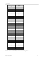
2.2.4 37-pin D-Sub Connector for Light Head Connection
The 37-Pin connector of Prostar is used to provide the light intensity output from Prostar to the
16/32 segment Light Head.
Prostar User’s Manual
8