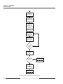
1
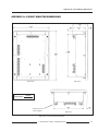
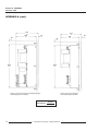
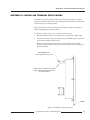
Contents 3-9 2-1/2 element metering system type 43 ................................................................................................. 23 3-10 3-11 DC control power connections ................................................................................................................ 24 Circuit monitors connected to one set of PTs and one CPT ................................................................ 25 3-12 3-13 Deriving L-L control power from phase PT inputs .............................................................................. 27 Deriving L-N control power from phase PT inputs ............................................................................. 27 3-14 3-15 Grounding the circuit monitor ................................................................................................................ 28 Circuit monitors connected to a system display for circuit monitors ................................................ 29 3-16 3-17 POWERLOGIC devices connected directly to a personal computer ................................................. 30 POWERLOGIC devices connected to an Ethernet gateway ............................................................... 31 3-18 3-19 POWERLOGIC devices connected to a PNIM ...................................................................................... 32 POWERLOGIC devices connected to a SY/MAX programmable controller ................................... 33 3-20 3-21 Daisy-chaining the RS-485 communications terminals ........................................................................ 35 Terminator placement when last device on the link is a circuit monitor .......................................... 36 3-22 4-1 Multipoint communications adapter connected to PNIM .................................................................. 37 Choosing a Setup option .......................................................................................................................... 41 4-2 4-3 Flowchart for front panel configuration ................................................................................................. 44 Flowchart for performing resets using the Resets option .................................................................... 57 4-4 A-1 Alarm/Relay setup .................................................................................................................................... 59 Circuit monitor dimensions ..................................................................................................................... 71 A-2 A-3 Circuit monitor dimensions with Input/Output and Voltage/Power Modules ............................. 72 Circuit monitor with Input/Output Module ........................................................................................ 72 C-1 Installing terminal strip covers ................................................................................................................ 75 TABLES 1-1 Summary of circuit monitor instrumentation ......................................................................................... 3 1-2 1-3 Class 3020 circuit monitors ......................................................................................................................... 3 Circuit monitor feature comparison ......................................................................................................... 3 3-1 3-2 Typical circuit monitor mounting locations .......................................................................................... 15 Supported system wiring connections ................................................................................................... 17 3-3 4-1 Maximum distances of comms link at different baud rates ................................................................ 34 Factory defaults for front panel configuration parameters ................................................................. 42 4-2 4-3 Supported system type system code selections .................................................................................... 48 Maximum distances of comms link at varying baud rates ................................................................. 53 1998 Square D Company All Rights Reserved iii