1
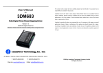
DM422C Digital Stepping Driver Manual V1.0
DM422C Digital Stepping Driver Manual V1.0
Connector P1 Configurations
Pin Function
PUL
Important NOTE: The driver must be mounted vertically onto a
plate or a heat sinking to maximize heat sink area as shown in the
above picture. Please use additional heat sinking or cool fan if
necessary.
DIR
OPTO
Operating Environment and other Specifications
Cooling
Operating Environment
ENA
Natural Cooling or Forced cooling
Avoid dust, oil fog and corrosive gases
Environment
Details
Pulse signal: In single pulse (pulse/direction) mode, this input represents pulse
signal, each rising or falling edge active (software configurable); 4-5V when
PUL-HIGH, 0-0.5V when PUL-LOW. In double pulse mode (pulse/pulse) ,
this input represents clockwise (CW) pulse,active both at high level and low
level (software configurable). For reliable response, pulse width should be
longer than 7.5μs. Series connect resistors for current-limiting when +12V or
+24V used. The same as DIR and ENA signals.
DIR signal: In single-pulse mode, this signal has low/high voltage levels,
representing two directions of motor rotation; in double-pulse mode (software
configurable), this signal is counter-clock (CCW) pulse,active both at high
level and low level (software configurable). For reliable motion response, DIR
signal should be ahead of PUL signal by 5μs at least. 4-5V when DIR-HIGH,
0-0.5V when DIR-LOW. Please note that rotation direction is also related to
motor-Drive wiring match. Exchanging the connection of two wires for a coil
to the Drive will reverse motion direction.
Opto-coupler power supply, and the typical voltage is +5V. Series connect
resistors (at the PUL, DIR, ENA terminals) for current-limiting when +12V or
+24V used.
Enable signal: This signal is used for enabling/disabling Drive. High level for
enabling the Drive and low level for disabling the Drive. Usually left
UNCONNECTED (ENABLED).
Selecting Active Pulse Edge and Control Signal Mode
Ambient Temperature
0℃-50℃ (32℉-122℉)
Humidity
40%RH-90%RH
The DM422C supports PUL/DIR and CW/CCW modes and pulse active at rising or falling edge. See
Operating Temperature
70℃ (158℉) Max
more information about these settings in Section 13. Default setting is PUL/DIR mode and rising
2
5.9m/s Max
Vibration
Storage Temperature
-20℃-65℃ (-4℉-149℉)
Weight
Approx. 100g (3.5274oz)
edge active.
Connector P2 Configurations
Pin Function
Details
3. Pin Assignment and Description
+Vdc
Power supply, 20~36 VDC, Including voltage fluctuation and EMF voltage
The DM422C has two connectors, connector P1 for control signals connections, and connector P2 for
GND
Power Ground.
power and motor connections. The following tables are brief descriptions of the two connectors.
A+, A-
Motor Phase A
More detailed descriptions of the pins and related issues are presented in section 4, 5, 9.
B+, B-
Motor Phase B
Tel: +086 0755-26434369
3
Web Site: www.leadshine.com
Tel: +086 0755-26434369
4
Web Site: www.leadshine.com