1
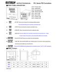
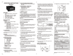
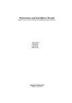
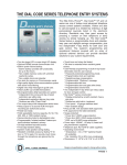
Operator Manual
Tempress® Systems, Inc.
Operator manual
M210_01 January 2004
This page intentionally left blank
TABLE OF CONTENTS
Table of contents
Preface .....................................................................................III
Tempress documentation set................................................................ III
User Definition ...................................................................................... IV
Notes, Cautions and Warnings .............................................................. V
Contents description ............................................................................. VI
Revision History .................................................................................... VI
1. Introduction .......................................................................1-1
1.1
General ..................................................................................... 1-1
1.2
Operator area description ......................................................... 1-2
2. Safety .................................................................................2-2
2.1
Emergency Off (EMO) .............................................................. 2-2
2.2
Alarm Signals............................................................................ 2-2
2.2.1
Buzzer / LED ............................................................. 2-2
2.2.2
Touchscreen.............................................................. 2-2
2.2.3
Light tower ................................................................. 2-3
2.2.4
TSC Alarm menu ....................................................... 2-3
2.3
Light tower signal description (optional).................................... 2-3
2.4
Toxic Material ........................................................................... 2-5
2.5
Safety measures ....................................................................... 2-5
3. Operator Instructions.....................................................2.5-1
3.1
3.2
Load or Unload process wafers ............................................. 3.1-1
3.1.1
Load process wafers............................................... 3.1-1
3.1.2
Unload wafers......................................................... 3.1-1
Selecting a new process recipe ............................................. 3.2-1
3.2.1
Touchscreen........................................................... 3.2-1
3.2.2
TSC-2 ..................................................................... 3.2-3
OPERATOR MANUAL
I
TABLE OF CONTENTS
3.3
3.4
3.5
3.6
Start/Continue a new process recipe ..................................... 3.3-1
3.3.1
Touchscreen........................................................... 3.3-1
3.3.2
TSC-2 ..................................................................... 3.3-2
Stop a running process recipe ............................................... 3.4-1
3.4.1
Touchscreen........................................................... 3.4-1
3.4.2
TSC-2 ..................................................................... 3.4-2
Abort a running process recipe .............................................. 3.5-1
3.5.1
Touchscreen........................................................... 3.5-1
3.5.2
TSC-2 ..................................................................... 3.5-2
Clear Alarms .......................................................................... 3.6-1
3.6.1
Required action....................................................... 3.6-1
3.6.2
Touchscreen........................................................... 3.6-1
3.6.3
TSC-2 ..................................................................... 3.6-2
OPERATOR MANUAL
II
PREFACE
Preface
This set of manuals explains how to operate a Horizontal Diffusion/LPCVD furnace.
Refer to the Touchscreen reference manual (M440.01) or the TSC-2 reference manual
(M450.03) for a full description of all operating screens.
For information about processing refer to the Process Manual (M220.xxx.02).
The Tempress Horizontal Diffusion Furnaces are fully described in the reference manuals
(M300 series).
Tempress documentation set
The complete Tempress documentation set includes:
•
Safety manual
•
Operator manual
•
Reference manuals
1. Loadstation
2. Furnace
3. Gas cabinet
4. Main Power cabinet
5. DPC
6. DTC
7. Touchscreen
8. TSC-2 (+ optional SECS/GEM)
•
Vendor documentation
Delivery’s on request:
•
Desired vendor documentation
•
Sic and Quartz drawings
•
RS422 protocol (DPC/DTC)
OPERATOR MANUAL
III
PREFACE
User Definition
It is strongly recommended that all users first read this manual before starting any procedure.
To produce an accessible manual suiting on various responsibilities, Tempress defines the
following users:
Operator
The operator is handling the process from loading until unloading of the wafers. Therefore
the operator needs to select a recipe, put the wafers on the boat, fill in Lot ID, Start the
process, monitor the progress and unload wafers.
Process engineer
The process engineer is a qualified chemical engineer, who is responsible for the process
recipes and their results. The process engineer writes, tests and releases new process recipes.
Service or Maintenance engineer
The maintenance engineer is a qualified electrician or mechanic, who is responsible for a
proper functioning system in accordance to its designated purpose. A Tempress qualified
service engineer will perform the first installation.
OPERATOR MANUAL
IV
PREFACE
Notes, Cautions and Warnings
Notes, Cautions and Warnings appear throughout this manual, where extra attention is
required to a particular (safety) item. Three levels can be distinguished:
NOTE
)
Notes alert to pay attention to items or procedures of special importance.
CAUTION
Cautions alert for a potentially hazardous situation that may result in minor
or moderate injuries.
Cautions can also alert for potential equipment and/or product damage.
WARNING
Warnings alert for conditions that may result in permanent and/or lethal
injuries.
OPERATOR MANUAL
V
PREFACE
Contents description
This manual is divided into the following sections and appendices:
Section 1
Introduction
Provides an overview of the Tempress Systems Inc. Horizontal furnace.
Section 2
Safety
Describes the safety components and functions. It describes all measures
that are required to provide a safe way of working.
Section 3
Operator Instructions
Describes all procedures that are required for the operator.
Revision History
This manual is revision 1 of the Operator Manual and is intended to explain the required
operator procedures. The function and screens it describes are based on the following
software releases:
•
TSC 2 version 6.3
(17-02-2003)
•
DPC 2.I.03
(17-02-2003)
•
DTC 2.F.02
(17-02-2003)
•
Touchscreen 2.I.05 (17-02-2003)
For minor software and hardware changes, addendum to this manual will be available. For
major changes, a new revision will be available. For information or other questions please
contact Tempress Systems Inc.
OPERATOR MANUAL
VI
INTRODUCTION
1.Introduction
1.1
General
The horizontal furnaces of Tempress Systems Inc. are developed according to the European
directives for Machinery (98/37/EC), Low Voltage (73/23/EC) and EMC (89/336/EEC).
The Tempress Diffusion system is a modular horizontal furnace designed to process (silicon)
wafers as part of the manufacturing technology of semiconductor, optical, MEMS and solar
devices.
Figure 1-1 shows an example of a standard L-shape diffusion system with 4 process tubes
shown without the partition of a cleanroom wall. It is a right-handed system, defined
according to the position of the furnace relative to an operator. Usually the system contains
more than 1 tube. Based on the number and size of tubes, the system is referred to as a 2, 3
or 4 stack.
Figure 1-1 is an example of a 4-stack system, allowing up to 4 different processes at any time.
The tubes are numbered from 1 to 4, with tube number 1 at the top and tube 4 at the
bottom. All tubes operate fully independently.
Main Power Cabinet
Figure 1-1 Schematic view of a right-handed 4-stack Diffusion System
OPERATOR MANUAL
1-1
INTRODUCTION
1.2
Operator area description
HOT SURFACE
Buzzer/LED
Light/Fan Switch
Touchscreen
EMO
Wafers
MOVING PART
Figure 1-2 Loadstation
The operator area is limited to the loadstation only. Figure 1-2 shows the relevant items.
The Loadstation part of a Tempress System should be placed in the cleanroom. The Furnace
and Gas cabinet can optionally be placed in the greyroom.
To load wafers, several loader types can be implemented, including the (default) inline loader,
the Amtech Atmoscan®, and the backmounted softlander. To prevent particles on the wafers
during the loading process, a constant horizontal laminar flow is created from the loadstation
into the cleanroom.
The loadstation is powered by 220V and has an illuminated On/Off switch for the fans and
the lights.
The remote control cabinet in the loadstation contains TFT-Touchscreens, one for each
tube. These supply the user interface for communication with the Digital System Controllers
(Digital Process Controller, Digital Temperature Controller and Digital Motion Controller).
OPERATOR MANUAL
1-2
SAFETY
2.Safety
This section contains a brief description of the safety features of a Tempress Horizontal
Diffusion System for the operator.
Operators must have a general knowledge of the technology involved in diffusion systems.
They should understand safety practices outlined in this manual.
The descriptions contained in this user manual are general in nature or generic. The actual
furnace may differ in minor detail from the furnace described in this manual, because of
customer specific requirements or modifications. Please refer to the Tempress Safety manual
for a complete description of available safety features.
2.1
Emergency Off (EMO)
Emergency Off (EMO) buttons are located around the system at accessible locations
according to EN 60204-1, especially EN 418. Pressing an EMO button turns off all power to
the system except to the fans on top of the furnace. This prevents fire hazard as a result of
high heat concentration in the furnace cabinet. Also those parts that are connected to a UPS
facility remain operational.
Press the EMO button when a person is in danger, when there is a fire, a water leak
or any other event that could be hazardous to life.
2.2
Alarm Signals
Alarms and alerts generated by tube controls are presented in several ways:
•
Buzzer / LED
•
Touch screen
•
Light tower
•
TSC-II
2.2.1
Buzzer / LED
Visible and audible alarm signals are generated by the DPC, DTC and the DMC. The visible
signals will be presented with a LED, located below the buzzer position as shown in Figure
1-1. Each tube process is represented by one LED and buzzer combination.
2.2.2
Touchscreen
The visible alarm signals will be presented
on the touchscreen bottom line. Alarms on
the Touchscreen are always in combination
with an audible signal.
Touching the screen deactivates the audible
signal.
A new Alarm or alert will not activate the
audible signal again before current alarm has
been solved.
OPERATOR MANUAL
2-2
SAFETY
2.2.3
Light tower
Alarms generated by the DPC, DTC and DMC will be made visible by three colors. Each
color of the light tower represents particular circumstances.
-
Green represents safe, operational condition.
Yellow represents warnings and alerts
Red represents alarms
See section 2.3 for a full description.
2.2.4
TSC Alarm menu
Activating the alarm menu gives an overview of all active and passed
alarms during the process. In case of an active alarm the “Alarm”
button start flashing on and off.
2.3
Light tower signal description (optional)
Red
Yellow
Green
Two light towers, one on top of the loadstation in the
cleanroom and one on top of the furnace in the greyroom, are
installed for fast anticipation on the status of the (production)
process. This section describes the function of each light and its
relation to the tube status.
A light tower is (default) comprised of 3 lights: from top to
bottom RED, YELLOW and GREEN.
The green and red light can indicate 2 signals:
1) OFF
2) ON
The yellow light can indicate 2 signals:
1) OFF
2) BLINK
Figure 2-1 Default light tower configuration
The light tower is controlled by a tower signal PLC that receives its commands from the
various controllers, among others DPC/DTC/DMC, Excess temperature controller, gas
detection system alarm and the TSC Host control.
In case the EMO-switch is activated or a power failure occurs for more than 4 seconds, the
power supply to the furnace will stop and also the light tower will be off.
The tower signal PLC is programmed by Tempress Systems Inc. and is not adjustable by
customers.
OPERATOR MANUAL
2-3
SAFETY
For a functional description of the light tower signals see table 1:
Signal
Green
Yellow
Mode
Description
ON
Operational
No warnings or messages
OFF
Not operational
BLINKING
N2 pressure-switch
No N2 gas flow detected
Air pressure switch
No Air flow detected
Torch temp (750)
The torch temperature has
to exceed 750oC
Torch Flame failure
There is no flame, the H2
valve will be closed
Torch H2/O2 ratio
The H2/O2 ratio exceeds the
safety value
Torch shell
The skin temperature of the
torch is too high
Temperature sensor
powerpack
Temperature powerpack is
too high
Bubbler temp
Bubbler temp is too high
Bubbler level
Fluid level is too low
O2- low
O2 flow is too low
Exhaust (Low/High)
Exhaust flow out of limits
Limit alarm (only if
programmed in the process
recipe)
Actual value is out of limits
Wait for operator (only if
programmed in the process
recipe)
Operator action is required
to continue
Process is finished
Red
Boat manual
Servo driver is in manual
mode
Maintenance mode
Maintenance mode is
activated
OFF
No alarm and/or alert
ON
Excess temperature
controller has been activated
Tube is overheated
Leakage detection
A gas or water leak has been
detected
No alarm and/or alert
No actual dangerous or
hazardous situation
OFF
Table 1 Light tower signal description
OPERATOR MANUAL
2-4
SAFETY
2.4
Toxic Material
The process engineer, responsible for all process related activities, has to inform the operator
about the hazards of the process.
2.5
Safety measures
Safety measures are indicated in the appropriate procedures
OPERATOR MANUAL
2-5
OPERATOR INSTRUCTION
3.Operator Instructions
This document describes the various procedures required for an operator. The procedures
describe how to load and unload wafers, how to select a new process recipe, how to
start/continue a process recipe, how to stop the timer of a running process recipe, how to
modify ‘Variable Commands’ when available and how to abort a running process recipe.
3.1
Load or Unload process wafers
Loading and unloading process wafers on the paddle is required before and after each process
run.
3.1.1
Load process wafers
•
•
•
3.1.2
Place the wafers on the wafer carriers, depending on the situation with (vacuum)
tweezers or a wafer transfer system.
Pick-up wafer carriers with a pick-up fork or automated loading tool.
Place the wafer carriers around the center of flatzone as indicated on the
loadstation.
Unload wafers
CAUTION
Wafers and paddle are hot.
•
•
•
Allow the wafers to cool down.
Pick-up wafer carriers with a pick-up fork or automated loading tool. (Amtech
Systems S300)
Remove the wafers from the wafer carriers, depending on the situation with
(vacuum) tweezers or a wafer transfer system.
OPERATOR MANUAL
3.1-1
OPERATOR INSTRUCTION
3.2
Selecting a new process recipe
A new process recipe needs to be selected so the new instructions can be executed. A new
process recipe can only be selected if the current process recipe is in ‘Step 0‘.
3.2.1
Touchscreen
1) return to the Main Menu by
pressing ‘ESC’ until the
following screen appears:
2) press ‘4’ to access ‘Tube
control’
3) press ‘6’ to ‘Select a Process
Recipes’
4) select the desired process
recipe by entering its
number.
OPERATOR MANUAL
3.2-1
OPERATOR INSTRUCTION
5) press ‘Yes’ to confirm the
question ‘Sure to SELECT
PROCESS recipe (Yes/No)?’
Note: selecting another process recipe is only possible if the current process recipe is in
Step 0.
OPERATOR MANUAL
3.2-2
OPERATOR INSTRUCTION
3.2.2
TSC-2
1) select the desired tube from the
pull-down menu or from the
‘Overview’ screen.
2) select ‘Operations’ to access the
operations screen.
3) Select the desired process recipe
from the pull-down menu
4) Press ‘Yes’ to confirm the
question ‘Are you sure to select
another process recipe?’
Note: selecting another process
recipe is only possible if the
current process recipe is in Step 0.
OPERATOR MANUAL
3.2-3
OPERATOR INSTRUCTION
3.3
Start/Continue a new process recipe
Two different situations require the ‘Start‘ command.
The first situation is starting a newly selected process recipe so it starts running from Step 0.
The second situation is starting a process recipe that has been stopped or is waiting for an
‘Operator‘ instruction.
3.3.1
Touchscreen
1) return to the Main Menu by
pressing ‘ESC’ until the
following screen appears:
2) press ‘4’ to access ‘Tube Control’
3) press ‘2’ to access ‘Start/Stop
Process Recipe’.
4) press ‘Start’ to start/continue the
selected process recipe.
OPERATOR MANUAL
3.3-1
OPERATOR INSTRUCTION
3.3.2
TSC-2
1) select the desired tube from the
pull-down menu or from the
‘Overview’ screen.
2) select ‘Operations’ to access
the operations screen.
3) press ‘Start’ to start the selected
process recipe from ‘Step 0’
4) press ‘Continue’ to start a
process recipe that has been
stopped or is waiting for an
‘Operator‘ instruction.
5) press ‘Yes’ to confirm the
question ‘Do you want to start?’
OPERATOR MANUAL
3.3-2
OPERATOR INSTRUCTION
3.4
Stop a running process recipe
Stopping a running process recipe may be required to temporarily stop the process recipe.
When activated, the ‘Stop‘ command will stop the timer while all given commands are maintained.
3.4.1
Touchscreen
1) return to the Main Menu by
pressing ‘ESC’ until the following
screen appears:
2) press ‘4’ to access ‘Tube Control’
3) press ‘2’ to access ‘Start/Stop
Process Recipe’
4) press ‘Stop’ to stop the selected
process recipe
OPERATOR MANUAL
3.4-1
OPERATOR INSTRUCTION
3.4.2
TSC-2
1) select the desired tube from the
pull-down menu or from the
‘Overview’ screen.
2) select ‘Operations’ to access
the operations screen.
3) Press ‘Pause’ to stop the selected
process recipe from the current
step.
OPERATOR MANUAL
3.4-2
OPERATOR INSTRUCTION
3.5
Abort a running process recipe
A manual ‘Abort‘ instruction may be required if the operator foresees a dangerous situation
or a continuous looped process recipe needs to be reset to Step 0 to allow selection of
another process recipe.
3.5.1
Touchscreen
1) return to the Main Menu by
pressing ‘ESC’ until the following
screen appears:
2) press ‘4’ to access ‘Tube Control’
3) press ‘3’ to access ‘Abort Process
Recipe’
4) press ‘Yes’ to confirm the
question ‘Are you sure you want
to abort?’
5) press ‘Yes’ again to activate the
abort command
OPERATOR MANUAL
3.5-1
OPERATOR INSTRUCTION
3.5.2
TSC-2
1) select the desired tube from the
pull-down menu or from the
‘Overview’ screen.
2) select ‘Operations’ to access the
operations screen.
3) Press ‘Abort’ to abort
selected process recipe.
4) Press ‘Yes’ to confirm the
question ‘Sure to abort?’
OPERATOR MANUAL
the
3.5-2
OPERATOR INSTRUCTION
3.6
Clear Alarms
Visible and audible Alarms signals are generated by the DPC and DTC. The visible alarms
will be presented both on the touchscreen and the TSC-2 computer(s), the audible alarms are
available on the touchscreen only.
Two different audible alarm signals are available:
•
operator alert: an intermittent beep-beep-beep to alert an operator for action (press ‘Start‘
for example)
•
alarm signal: a continuous beeeeeeeeeeeeep to alert for an alarm situation
3.6.1
•
•
3.6.2
Required action
Operator alert signals (beep-beep-beep) require the operator to press ‘Start‘ to have the
furnace proceed to the next step in the process.
Alarm situation signals (beeeeeeeeeeep) require the operator to alert the responsible
person(s) immediately.
Touchscreen
1) touch the touchscreen to silence
the buzzer
2) read the alarm message in the
bottom line of the screen
3) take the appropriate action as
described in section 3.6.1.
OPERATOR MANUAL
3.6-1
OPERATOR INSTRUCTION
3.6.3
TSC-2
1) the overview screen gives an
instant view of which tubes are in
alarm in RED
2) select the desired tube from the
pull-down menu or from the
‘Overview’ screen
4) select the ‘Alarm’ screen
3) read the alarm message(s)
4) take the appropriate action as
described in section 3.6.1
OPERATOR MANUAL
3.6-2