1
User’s Manual
CubeSuite+ V1.00.00
Integrated Development Environment
User’s Manual: 78K0 Build
Target Device
78K0 Microcontroller
All information contained in these materials, including products and product specifications,
represents information on the product at the time of publication and is subject to change by
Renesas Electronics Corp. without notice. Please review the latest information published by
Renesas Electronics Corp. through various means, including the Renesas Electronics Corp.
website (http://www.renesas.com).
www.renesas.com
Rev.1.00
Apr 2011
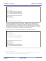
Notice
1.
2.
3.
4.
5.
6.
7.
All information included in this document is current as of the date this document is issued. Such information, however, is
subject to change without any prior notice. Before purchasing or using any Renesas Electronics products listed herein, please
confirm the latest product information with a Renesas Electronics sales office. Also, please pay regular and careful attention to
additional and different information to be disclosed by Renesas Electronics such as that disclosed through our website.
Renesas Electronics does not assume any liability for infringement of patents, copyrights, or other intellectual property rights
of third parties by or arising from the use of Renesas Electronics products or technical information described in this document.
No license, express, implied or otherwise, is granted hereby under any patents, copyrights or other intellectual property rights
of Renesas Electronics or others.
You should not alter, modify, copy, or otherwise misappropriate any Renesas Electronics product, whether in whole or in part.
Descriptions of circuits, software and other related information in this document are provided only to illustrate the operation of
semiconductor products and application examples. You are fully responsible for the incorporation of these circuits, software,
and information in the design of your equipment. Renesas Electronics assumes no responsibility for any losses incurred by
you or third parties arising from the use of these circuits, software, or information.
When exporting the products or technology described in this document, you should comply with the applicable export control
laws and regulations and follow the procedures required by such laws and regulations. You should not use Renesas
Electronics products or the technology described in this document for any purpose relating to military applications or use by
the military, including but not limited to the development of weapons of mass destruction. Renesas Electronics products and
technology may not be used for or incorporated into any products or systems whose manufacture, use, or sale is prohibited
under any applicable domestic or foreign laws or regulations.
Renesas Electronics has used reasonable care in preparing the information included in this document, but Renesas Electronics
does not warrant that such information is error free. Renesas Electronics assumes no liability whatsoever for any damages
incurred by you resulting from errors in or omissions from the information included herein.
Renesas Electronics products are classified according to the following three quality grades: “Standard”, “High Quality”, and
“Specific”. The recommended applications for each Renesas Electronics product depends on the product’s quality grade, as
indicated below. You must check the quality grade of each Renesas Electronics product before using it in a particular
application. You may not use any Renesas Electronics product for any application categorized as “Specific” without the prior
written consent of Renesas Electronics. Further, you may not use any Renesas Electronics product for any application for
which it is not intended without the prior written consent of Renesas Electronics. Renesas Electronics shall not be in any way
liable for any damages or losses incurred by you or third parties arising from the use of any Renesas Electronics product for an
application categorized as “Specific” or for which the product is not intended where you have failed to obtain the prior written
consent of Renesas Electronics. The quality grade of each Renesas Electronics product is “Standard” unless otherwise
expressly specified in a Renesas Electronics data sheets or data books, etc.
“Standard”:
8.
9.
10.
11.
12.
Computers; office equipment; communications equipment; test and measurement equipment; audio and visual
equipment; home electronic appliances; machine tools; personal electronic equipment; and industrial robots.
“High Quality”: Transportation equipment (automobiles, trains, ships, etc.); traffic control systems; anti-disaster systems; anticrime systems; safety equipment; and medical equipment not specifically designed for life support.
“Specific”:
Aircraft; aerospace equipment; submersible repeaters; nuclear reactor control systems; medical equipment or
systems for life support (e.g. artificial life support devices or systems), surgical implantations, or healthcare
intervention (e.g. excision, etc.), and any other applications or purposes that pose a direct threat to human life.
You should use the Renesas Electronics products described in this document within the range specified by Renesas Electronics,
especially with respect to the maximum rating, operating supply voltage range, movement power voltage range, heat radiation
characteristics, installation and other product characteristics. Renesas Electronics shall have no liability for malfunctions or
damages arising out of the use of Renesas Electronics products beyond such specified ranges.
Although Renesas Electronics endeavors to improve the quality and reliability of its products, semiconductor products have
specific characteristics such as the occurrence of failure at a certain rate and malfunctions under certain use conditions. Further,
Renesas Electronics products are not subject to radiation resistance design. Please be sure to implement safety measures to
guard them against the possibility of physical injury, and injury or damage caused by fire in the event of the failure of a
Renesas Electronics product, such as safety design for hardware and software including but not limited to redundancy, fire
control and malfunction prevention, appropriate treatment for aging degradation or any other appropriate measures. Because
the evaluation of microcomputer software alone is very difficult, please evaluate the safety of the final products or system
manufactured by you.
Please contact a Renesas Electronics sales office for details as to environmental matters such as the environmental
compatibility of each Renesas Electronics product. Please use Renesas Electronics products in compliance with all applicable
laws and regulations that regulate the inclusion or use of controlled substances, including without limitation, the EU RoHS
Directive. Renesas Electronics assumes no liability for damages or losses occurring as a result of your noncompliance with
applicable laws and regulations.
This document may not be reproduced or duplicated, in any form, in whole or in part, without prior written consent of Renesas
Electronics.
Please contact a Renesas Electronics sales office if you have any questions regarding the information contained in this
document or Renesas Electronics products, or if you have any other inquiries.
(Note 1) “Renesas Electronics” as used in this document means Renesas Electronics Corporation and also includes its majorityowned subsidiaries.
(Note 2) “Renesas Electronics product(s)” means any product developed or manufactured by or for Renesas Electronics.
How to Use This Manual
This manual describes the role of the CubeSuite+ integrated development environment for developing application
systems for 78K0 microcontrollers, and provides an outline of its features.
CubeSuite+ is an integrated development environment (IDE) for 78K0 microcontrollers, integrating the necessary
tools for the development phase of software (e.g. design, implementation, and debugging) into a single platform.
By providing an integrated environment, it is possible to perform all development using just this product, without
the need to use many different tools separately.
Readers
This manual is intended for users who wish to understand the functions of the
CubeSuite+ and design software and hardware application systems.
Purpose
This manual is intended to give users an understanding of the functions of the
CubeSuite+ to use for reference in developing the hardware or software of systems
using these devices.
Organization
This manual can be broadly divided into the following units.
CHAPTER 1 GENERAL
CHAPTER 2 FUNCTIONS
CHAPTER 3 BUILD OUTPUT LISTS
CHAPTER 4 SAMPLE PROGRAMS
CHAPTER 5 CAUTIONS
APPENDIX A WINDOW REFERENCE
APPENDIX B COMMAND REFERENCE
APPENDIX C INDEX
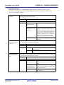
How to Read This Manual It is assumed that the readers of this manual have general knowledge of electricity, logic
circuits, and microcontrollers.
Conventions
Data significance:
Higher digits on the left and lower digits on the right
–––
Active low representation: XXX (overscore over pin or signal name)
Note:
Footnote for item marked with Note in the text
Caution:
Information requiring particular attention
Remark:
Supplementary information
Numeric representation:
Decimal … XXXX
Hexadecimal … 0xXXXX
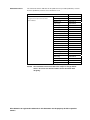
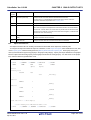
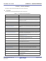
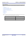
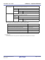
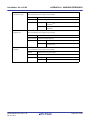
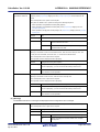
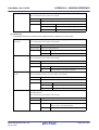
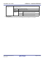
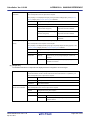
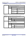
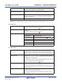
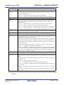
Related Documents
The related documents indicated in this publication may include preliminary versions.
However, preliminary versions are not marked as such.
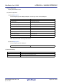
Document Name
Document No.
CubeSuite+
Start
R20UT0545E
Integrated Development Environment
78K0 Design
R20UT0546E
User's Manual
78K0R Design
R20UT0547E
Caution
RL78 Design
R20UT0548E
V850 Design
R20UT0549E
R8C Design
R20UT0550E
78K0 Coding
R20UT0551E
RL78,78K0R Coding
R20UT0552E
V850 Coding
R20UT0553E
Coding for CX Compiler
R20UT0554E
R8C Coding
R20UT0576E
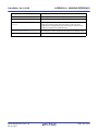
78K0 Build
This manual
RL78,78K0R Build
R20UT0556E
V850 Build
R20UT0557E
Build for CX Compiler
R20UT0558E
R8C Build
R20UT0575E
78K0 Debug
R20UT0559E
78K0R Debug
R20UT0560E
RL78 Debug
R20UT0561E
V850 Debug
R20UT0562E
R8C Debug
R20UT0574E
Analysis
R20UT0563E
Message
R20UT0407E
The related documents listed above are subject to change without
notice. Be sure to use the latest edition of each document when
designing.
All trademarks or registered trademarks in this document are the property of their respective
owners.
[MEMO]
[MEMO]
[MEMO]
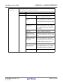
TABLE OF CONTENTS
CHAPTER 1 GENERAL ... 12
1.1 Overview ... 12
1.2 Features ... 13
CHAPTER 2 FUNCTIONS ... 14
2.1 Overview ... 14
2.1.1 Create a load module ... 14
2.1.2 Create a user library ... 15
2.2 Change the Build Tool Version ... 16
2.3 Set Build Target Files ... 17
2.3.1 Set a startup routine ... 17
2.3.2 Add a file to a project ... 19
2.3.3 Remove a file from a project ... 23
2.3.4 Remove a file from the build target ... 24
2.3.5 Classify a file into a category ... 24
2.3.6 Change the file display order ... 25
2.3.7 Update file dependencies ... 26
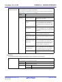
2.4 Set the Type of the Output File ... 29
2.4.1 Change the output file name ... 29
2.4.2 Output an assemble list ... 30
2.4.3 Output map information ... 31
2.4.4 Output symbol information ... 31
2.5 Set Compile Options ... 33
2.5.1 Perform optimization with the code size precedence ... 34
2.5.2 Perform optimization with the execution speed precedence ... 34
2.5.3 Add an include path ... 34
2.5.4 Set a macro definition ... 36
2.5.5 Enable C++ comments ... 37
2.5.6 Use floating point-compatible standard input/output functions ... 37
2.5.7 Change the setting to use the multiplier and divider ... 37
2.6 Set Assemble Options ... 38
2.6.1 Add an include path ... 38
2.6.2 Set a macro definition ... 40
2.7 Set Link Options ... 41
2.7.1 Add a user library ... 42
2.8 Set Object Convert Options ... 43
2.8.1 Set the output of a hex file ... 44
2.9 Set Create Library Options ... 45
2.9.1 Set the output of a library file ... 45
2.10 Set Variables Relocation Options ... 46
2.10.1 Efficiently allocate variables ... 46
2.11
2.12
2.13
2.14
2.15
2.16
2.17
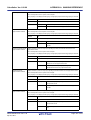
2.10.2 Display ROM/RAM usage ... 50
Set Memory Bank Relocation Options ... 51
2.11.1 Relocate C source files to the optimum area ... 51
Set Build Options Separately ... 58
2.12.1 Set build options at the project level ... 58
2.12.2 Set build options at the file level ... 58
Prepare for Using On-chip Debugger ... 61
Prepare for Implementing Boot-flash Relink Function ... 63
2.14.1 Prepare the build target files ... 63
2.14.2 Set the boot area project ... 63
2.14.3 Set the flash area project ... 66
Make Settings for Build Operations ... 70
2.15.1 Set the link order of files ... 70
2.15.2 Change the file build order of subprojects ... 71
2.15.3 Display a list of build options ... 71
2.15.4 Change the file build target project ... 71
2.15.5 Add a build mode ... 73
2.15.6 Change the build mode ... 75
2.15.7 Delete a build mode ... 76
2.15.8 Set the current build options as the standard for the project ... 77
Run a Build ... 78
2.16.1 Run a build of updated files ... 80
2.16.2 Run a build of all files ... 81
2.16.3 Run a build in parallel with other operations ... 81
2.16.4 Run builds in batch with build modes ... 83
2.16.5 Compile/assemble individual files ... 84
2.16.6 Stop running a build ... 85
2.16.7 Save the build results to a file ... 85
2.16.8 Delete intermediate files and generated files ... 85
Estimate the Stack Capacity ... 87
2.17.1 Starting and exiting ... 87
2.17.2 Check the call relationship ... 88
2.17.3 Check the stack information ... 89
2.17.4 Check unknown functions ... 90
2.17.5 Change the frame size ... 91
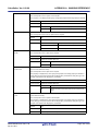
CHAPTER 3 BUILD OUTPUT LISTS ... 93
3.1 C Compiler ... 93
3.1.1 Assembler source file ... 93
3.1.2 Error list file ... 96
3.1.3 Preprocess list file ... 99
3.1.4 Cross reference list file ... 100
3.2 Assembler ... 103
3.2.1 Assemble list file headers ... 103
3.2.2 Assemble list ... 104
3.2.3 Symbol list ... 106
3.2.4 Cross reference list ... 107
3.2.5 Error list ... 108
3.3 Linker ... 110
3.3.1 Link list file headers ... 110
3.3.2 Map list ... 111
3.3.3 Public symbol list ... 112
3.3.4 Local symbol list ... 113
3.3.5 Error list ... 114
3.4 Object Converter ... 115
3.4.1 Error list ... 115
3.5 Librarian ... 116
3.5.1 Library information output list ... 116
3.6 List Converter ... 117
3.6.1 Absolute assemble list ... 117
3.6.2 Error list ... 117
3.7 Variables Information File Generator ... 118
3.7.1 Variables information file ... 118
3.8 Memory Bank Relocation Support Tool ... 121
3.8.1 Function information file ... 121
3.8.2 Replacement information file ... 122
3.8.3 Object information file ... 125
3.8.4 Reference information file ... 127
CHAPTER 4 SAMPLE PROGRAMS ... 128
4.1 C Compiler ... 128
4.1.1 C source file ... 128
4.2 Assembler ... 130
4.2.1 k0main.asm ... 130
4.2.2 k0sub.asm ... 131
CHAPTER 5 CAUTIONS ... 132
APPENDIX A WINDOW REFERENCE ... 139
A.1 Description ... 139
APPENDIX B COMMAND REFERENCE ... 319
B.1 C Compiler ... 319
B.1.1 I/O files ... 320
B.1.2 Functions ... 321
B.1.3 Method for manipulating ... 323
B.1.4 Option ... 327
B.2 Assembler ... 380
B.2.1 I/O files ... 380
B.2.2 Functions ... 381
B.2.3 Method for manipulating ... 381
B.2.4 Option ... 384
B.3 Linker ... 424
B.4
B.5
B.6
B.7
B.3.1 I/O files ... 424
B.3.2 Functions ... 425
B.3.3 Method for manipulating ... 425
B.3.4 Option ... 429
B.3.5 Boot-flash relink function ... 468
Object Converter ... 481
B.4.1 I/O files ... 481
B.4.2 Functions ... 482
B.4.3 Method for manipulating ... 495
B.4.4 Option ... 498
Librarian ... 514
B.5.1 I/O files ... 514
B.5.2 Functions ... 515
B.5.3 Method for manipulating ... 516
B.5.4 Option ... 519
B.5.5 Subcommands ... 527
List Converter ... 537
B.6.1 I/O files ... 538
B.6.2 Functions ... 538
B.6.3 Method for manipulating ... 541
B.6.4 Option ... 543
Variables Information File Generator ... 550
B.7.1 I/O files ... 550
B.7.2 Functions ... 551
B.7.3 Variables/functions information ... 551
B.7.4 Method for manipulating ... 555
B.7.5 Option ... 558
APPENDIX C INDEX ... 563
CubeSuite+ Ver.1.00.00
CHAPTER 1 GENERAL
CHAPTER 1 GENERAL
This chapter explains the product overview of the build tool.
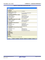
1.1
Overview
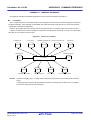
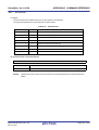
The build tool is comprised of components provided by this product. It enables various types of information to be configured via a GUI tool, enabling you to generate load module file, hex file, or library file from your source files, according to
your objectives.
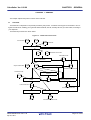
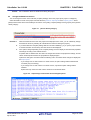
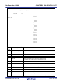
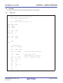
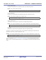
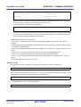
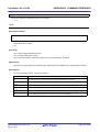
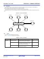
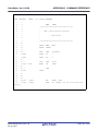
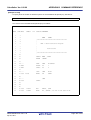
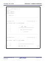
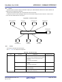
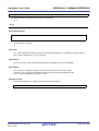
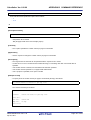
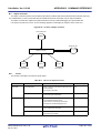
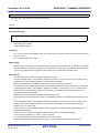
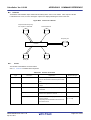
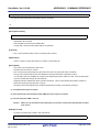
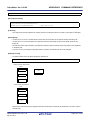
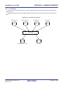
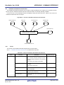
The build tool process flow is shown below.
Figure 1-1. Build Tool Process Flow
C source files
...
Include file
C compiler
Assembler source files
...
Assemble list file
Assembler
Object module files
...
Variables information file generator
Variables information file
Link directive file
Librarian
Memory bank support tool
Linker
Library file
Load module file
Function information file
Object converter
Hex file
R20UT0555EJ0100 Rev.1.00
Apr 01, 2011
List converter
Absolute assemble list file
Page 12 of 570
CubeSuite+ Ver.1.00.00
1.2
CHAPTER 1 GENERAL
Features
The features of the build tools are shown below.
- Optimization function
You can generate efficient object module files by performing optimizations such as prioritizing code size or execution speed when compiling.
- ROMization function
ROMization is processing that locates in ROM the initial values for external variables that have initial values and
copies them to RAM when the system is executed.
The CA78K0 provides a program startup routine with ROMization processing so you can eliminate the effort to
code ROMization processing at startup.
Remark
See "CubeSuite+ 78K0 Coding" about the ROMization function.
- Macro function
When you write the same instructions multiple times in the assembler source file, you can define that instructions
as a single macro name.
Remark
See "CubeSuite+ 78K0 Coding" about the macro function.
R20UT0555EJ0100 Rev.1.00
Apr 01, 2011
Page 13 of 570
CubeSuite+ Ver.1.00.00
CHAPTER 2 FUNCTIONS
CHAPTER 2 FUNCTIONS
This chapter describes the build procedure using CubeSuite+ and about the main build functions.
2.1
Overview
This section describes how to create a load module and user library.
2.1.1
Create a load module
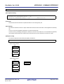
The procedure for creating a load module is shown below.
(1) Create or load a project
Create a new project, or load an existing one.
Remark
See "CubeSuite+ Start" for details about creating a new project or loading an existing one.
(2) Set a build target project
Set a build target project (see "2.15 Make Settings for Build Operations").
If there is no subproject, the project is always active.
Remarks 1.
2.
If there is no subproject in the project, the project is always active.
When setting a build mode, add the build mode (see "2.15.5 Add a build mode").
(3) Set build target files
Add or remove build target files and update the dependencies (see "2.3 Set Build Target Files").
Remarks 1.
2.
See "2.7.1 Add a user library" for the method of adding a user library to the project.
Also, you can set the link order of object module files and library files (see "2.15.1 Set the link
order of files").
(4) Specify the output of a load module
Select the type of the load module to be generated (see "2.4 Set the Type of the Output File").
(5) Set build options
Set the options for the compiler, assembler, linker, and the like (see "2.5 Set Compile Options", "2.6 Set
Assemble Options", "2.7 Set Link Options").
(6) Run a build
Run a build (see "2.16 Run a Build").
The following types of builds are available.
- Build (see "2.16.1 Run a build of updated files")
- Rebuild (see "2.16.2 Run a build of all files")
- Rapid build (see "2.16.3 Run a build in parallel with other operations")
- Batch build (see "2.16.4 Run builds in batch with build modes")
Remark
If there are any commands you wish to run before or after the build process, on the Property panel,
from the [Common Options] tab, in the [Others] category, set the [Commands executed before build
processing] and [Commands executed after build processing] properties.
If there are any commands you wish to run before or after the build process at the file level, you can set
R20UT0555EJ0100 Rev.1.00
Apr 01, 2011
Page 14 of 570
CubeSuite+ Ver.1.00.00
CHAPTER 2 FUNCTIONS
them from the [Individual Compile Options] tab (for a C source file) and [Individual Assemble Options]
tab (for an assembler source file).
(7) Save the project
Save the setting contents of the project to the project file.
Remark
2.1.2
See "CubeSuite+ Start" for details about saving the project.
Create a user library
The procedure for creating a user library is shown below.
(1) Create or load a project
Create a new project, or load an existing one.
When you create a new project, set a library project.
Remark
See "CubeSuite+ Start" for details about creating a new project or loading an existing one.
(2) Set a build target project
Set a build target project (see "2.15 Make Settings for Build Operations").
If there is no subproject, the project is always active.
Remarks 1.
2.
If there is no subproject in the project, the project is always active.
When setting a build mode, add the build mode (see "2.15.5 Add a build mode").
(3) Set build target files
Add or remove build target files and update the dependencies (see "2.3 Set Build Target Files").
(4) Set build options
Set the options for the compiler, assembler, librarian, and the like (see "2.5 Set Compile Options", "2.6 Set
Assemble Options", "2.9 Set Create Library Options").
(5) Run a build
Run a build (see "2.16 Run a Build").
The following types of builds are available.
- Build (see "2.16.1 Run a build of updated files")
- Rebuild (see "2.16.2 Run a build of all files")
- Rapid build (see "2.16.3 Run a build in parallel with other operations")
- Batch build (see "2.16.4 Run builds in batch with build modes")
Remark
If there are any commands you wish to run before or after the build process, on the Property panel,
from the [Common Options] tab, in the [Others] category, set the [Commands executed before build
processing] and [Commands executed after build processing] properties.
If there are any commands you wish to run before or after the build process at the file level, you can set
them from the [Individual Compile Options] tab (for a C source file) and [Individual Assemble Options]
tab (for an assembler source file).
(6) Save the project
Save the setting contents of the project to the project file.
R20UT0555EJ0100 Rev.1.00
Apr 01, 2011
Page 15 of 570
CubeSuite+ Ver.1.00.00
Remark
2.2
CHAPTER 2 FUNCTIONS
See "CubeSuite+ Start" for details about saving the project.
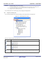
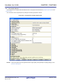
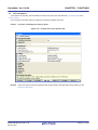
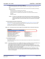
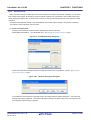
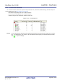
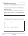
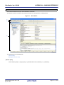
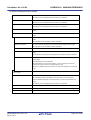
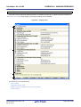
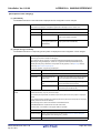
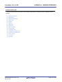
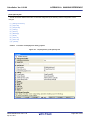
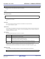
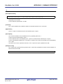
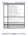
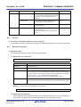
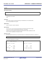
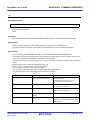
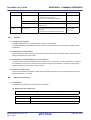
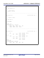
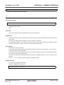
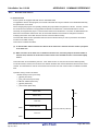
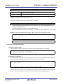
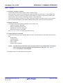
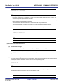
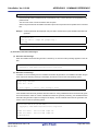
Change the Build Tool Version
You can change the version of the build tool (compiler package) used in the project (main project or subproject).
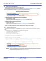
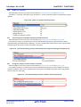
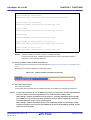
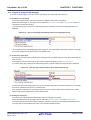
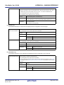
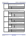
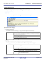
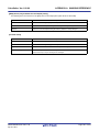
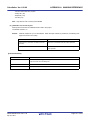
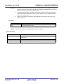
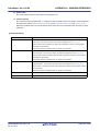
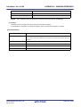
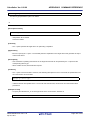
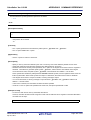
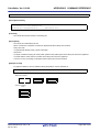
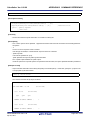
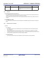
Select the build tool node on the project tree and select the [Common Options] tab on the Property panel. Select
[Always latest version which was installed] or the version on the [Using compiler package version] property in the [Version
Select] category.
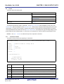
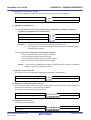
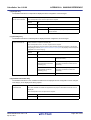
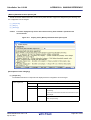
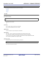
Figure 2-1. [Version Select] Category
Remarks 1.
When the build tool used in the main project and subprojects is the same, you can collectively change
the build tool version by selecting all of the Build tool nodes and setting the property.
2.
If you have selected a compiler package that has not been installed (e.g. if you open a project created
in another execution environment), then that version is also displayed.
3.
If the options change depending on the compiler package, then the display of the build tool's properties
will change according to the selected version.
Properties that are hidden when the version is changed are saved in the project file's settings, and the
values will be reproduced when the properties are displayed again.
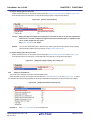
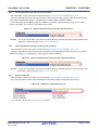
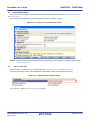
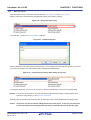
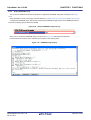
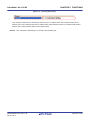
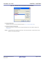
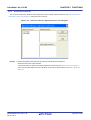
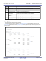
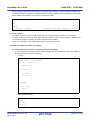
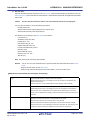
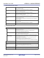
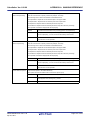
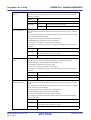
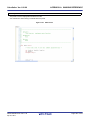
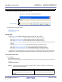
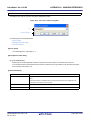
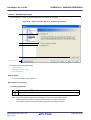
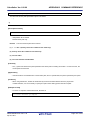
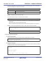
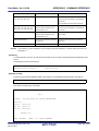
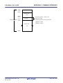
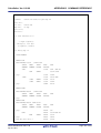
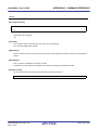
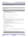
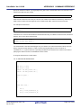
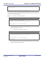
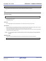
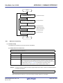
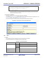
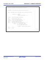
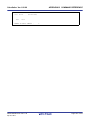
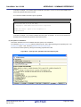
Options are changed in accordance with the following rules. Information about changes is displayed in
the Output panel.
- If you change from an older version to a newer version, the option settings will be inherited and
converted (only if necessary).
- If you change from a newer version to an older version, only identical option settings will be
inherited.
Options that only exist in the older version will be set to the default values.
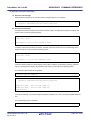
Figure 2-2. Output Image of Information about Changed Options
R20UT0555EJ0100 Rev.1.00
Apr 01, 2011
Page 16 of 570
CubeSuite+ Ver.1.00.00
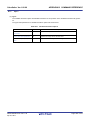
2.3
CHAPTER 2 FUNCTIONS
Set Build Target Files
Before running a build, you must add the build target files (such as C source file, assembler source file) to the project.
This section explains operations on setting files in the project.
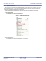
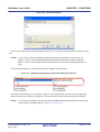
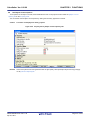
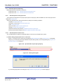
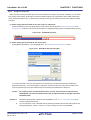
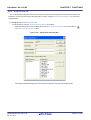
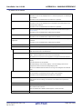
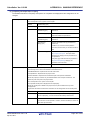
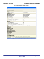
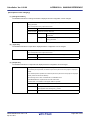
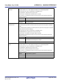
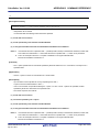
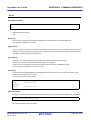
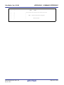
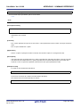
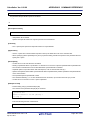
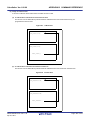
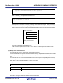
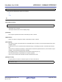
2.3.1
Set a startup routine
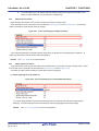
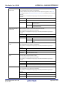
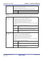
(1) Using the standard startup routine
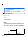
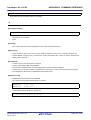
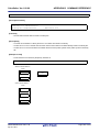
Select the build tool node on the project tree and select the [Compile Options] tab on the Property panel.
To use the standard startup routine, select [Yes(Normal)]/[Yes(For boot area)]/[Yes(For flash area)] on the [Use
standard startup routine] property in the [Startup] category.
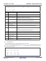
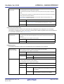
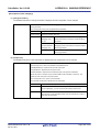
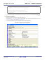
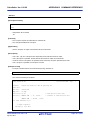
Figure 2-3. [Use standard startup routine] Property
The object file name of the standard startup routine to be used will be displayed on the [Using standard startup
routine] property.
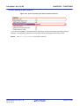
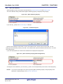
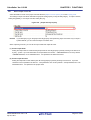
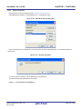
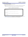
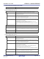
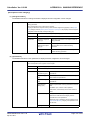
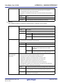
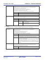
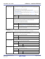
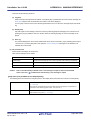
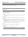
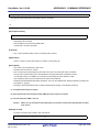
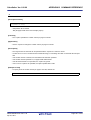
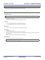
(2) Using other than the standard startup routine
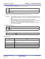
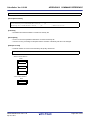
Select the build tool node on the project tree and select the [Compile Options] tab on the Property panel.
To use other than the standard startup routine, select [No] on the [Use standard startup routine] property in the
[Startup] category ([Yes(Normal)] is selected by default).
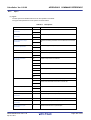
Figure 2-4. [Use standard startup routine] Property
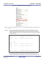
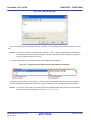
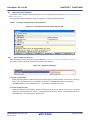
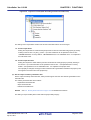
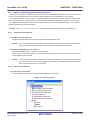
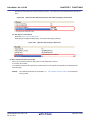
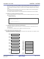
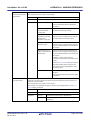
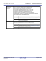
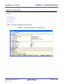
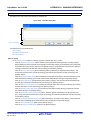
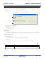
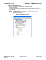
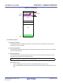
Next, add a startup file (a file that the startup routine is described) to the Startup node on the project tree. See
"2.3.2 Add a file to a project" for the method of adding the file to the project tree.
R20UT0555EJ0100 Rev.1.00
Apr 01, 2011
Page 17 of 570
CubeSuite+ Ver.1.00.00
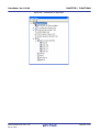
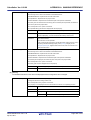
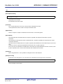
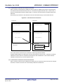
CHAPTER 2 FUNCTIONS
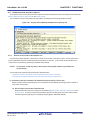
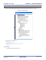
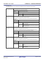
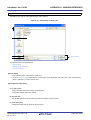
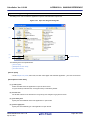
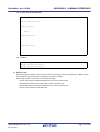
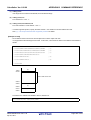
Figure 2-5. Project Tree Panel (After Adding Startup File)
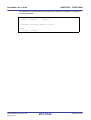
Caution
A build target file added directly below the Startup node on the project tree is treated as the
startup file. It is not treated as a startup file if it is added to the category below the Startup node.
When adding a startup file to the Startup node, if a startup file has already been added then only
the latest startup file to be added is targeted by a build; any such files added prior to this one
will not be targeted.
When setting a startup file that is not targeted by a build as a build target, if other startup files
have also been added then the file will be targeted by the build, and the others will not be
targeted.
Remark
See "CubeSuite+ 78K0 Coding" for the method of creating the startup routine.
R20UT0555EJ0100 Rev.1.00
Apr 01, 2011
Page 18 of 570
CubeSuite+ Ver.1.00.00
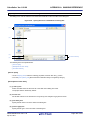
2.3.2
CHAPTER 2 FUNCTIONS
Add a file to a project
Files can be added to a project by the following methods.
- Adding an existing file
- Creating and adding an empty file
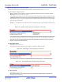
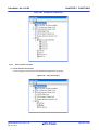
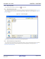
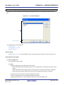
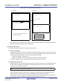
(1) Adding an existing file
(a) Add individual files
Drag a folder from Explorer or the like, and drop it onto the empty space below the project tree.
The file is added below the File node.
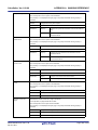
Figure 2-6. Project Tree Panel (File Drop Location)
Drop the file here
Caution
To add a startup routine, drop a file onto the Startup node. See "2.3.1 Set a startup routine"
for details about using a startup routine.
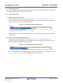
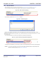
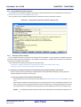
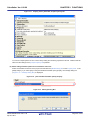
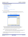
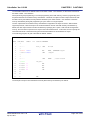
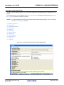
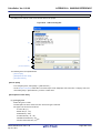
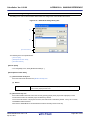
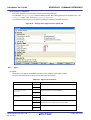
(b) Add a folder
Drag a folder from Explorer or the like, and drop it onto the empty space below the project tree. The Add
Folder and File dialog box opens.
Remark
You can also add multiple folders to the project at the same time by dragging multiple folders at
same time and dropping them onto the project tree.
Caution
When a folder with the name that is more than 200 characters is dropped, the folder is
added to the project tree as a category with the name that 201st character and after are
deleted.
R20UT0555EJ0100 Rev.1.00
Apr 01, 2011
Page 19 of 570
CubeSuite+ Ver.1.00.00
CHAPTER 2 FUNCTIONS
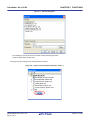
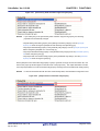
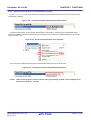
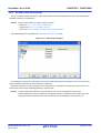
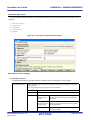
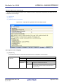
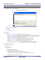
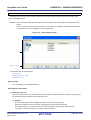
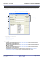
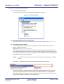
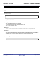
Figure 2-7. Add Folder and File Dialog Box
In the dialog, select the file types to add to the project, specify the number of subfolder levels to add, and then
click the [OK] button.
Remark
You can select multiple file types by left clicking while holding down the [Ctrl] or [Shift] key.
If nothing is selected, it is assumed that all types are selected.
The folder is added below the File node.
Note that on the project tree, the folder is the category.
Remark
When the category node created by the user exists, you can add a file below the node by dropping the
file onto the node (see "2.3.5 Classify a file into a category" for a category node).
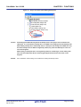
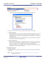
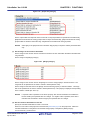
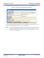
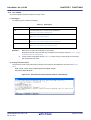
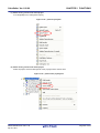
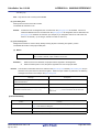
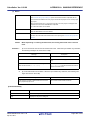
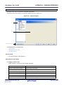
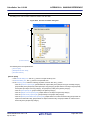
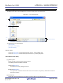
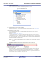
(2) Creating and adding an empty file
On the project tree, select either one of the Project node, Subproject node, or File node, and then select [Add] >>
[Add New File...] from the context menu. The Add File dialog box opens.
R20UT0555EJ0100 Rev.1.00
Apr 01, 2011
Page 20 of 570
CubeSuite+ Ver.1.00.00
CHAPTER 2 FUNCTIONS
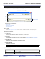
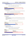
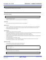
Figure 2-8. Add File Dialog Box
In the dialog box, specify the file to be created and then click the [OK] button.
The file is added below the File node.
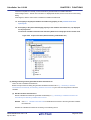
The project tree after adding the file will look like the one below.
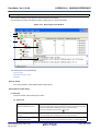
Figure 2-9. Project Tree Panel (After Adding File "main.c")
R20UT0555EJ0100 Rev.1.00
Apr 01, 2011
Page 21 of 570
CubeSuite+ Ver.1.00.00
CHAPTER 2 FUNCTIONS
Figure 2-10. Project Tree Panel (After Adding Folder "src")
Remark
The location of the file added below the File node depends on the current file display order setting. See
"2.3.6 Change the file display order" for the method of changing the file display order.
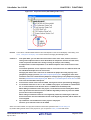
Cautions 1.
If the paths differ, you can add source files with the same name. Note, however, that if the
setting of the output file name is left as the default, the output files will have the same name,
which will prevent the build from running correctly (for example, when adding
D:\sample1\func.c and D:\sample2\func.c, the default output file name for these files is both
func.rel).
To avoid this problems, set the output file name for each of those files to a different name with
the individual build options for the source files.
Changing the name of the C source file is made with the [Object file name] property in the
[Output File] category from the [Individual Compile Options] tab. Changing the name of the
assembler source file is made with the [Object file name] property in the [Output File] category
from the [Individual Assemble Options] tab. See "2.12.2 Set build options at the file level" for
how to set the individual build options.
2.
3.
If source files with the same name are added, the target file cannot opened during debugging.
If a file with an extension of "dr" or "dir" is added to the project, it is treated as a link directive
file. It is also treated as a link directive file if it is added below the Startup node.
When adding a link directive file to the project, if a link directive file has already been added
then only the latest link directive file to be added is targeted by a build; any such files added
prior to this one will not be targeted.
When setting a link directive file that is not targeted by a build as a build target, if other link
directive files have also been added then the file will be targeted by the build, and the others will
not be targeted.
4.
Up to 5000 files can be added to the main project or subproject.
However, up to 1000 souce files can be added.
When a new file is added, an empty file is created in the location specified in the Add File dialog box.
By double clicking the file name on the project tree, you can open the Editor panel and edit the file.
R20UT0555EJ0100 Rev.1.00
Apr 01, 2011
Page 22 of 570
CubeSuite+ Ver.1.00.00
CHAPTER 2 FUNCTIONS
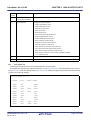
The files that can be opened with the Editor panel are shown below.
- C source file (.c)
- Assembler source file (.asm)
- Header file (.h, .inc)
- Link directive file (.dr, .dir)
- Variables information file (.vfi)
- Function information file (.fin)Note
- Map file (.map)
- Symbol table file (.sym)
- Hex file (.hex, .hxb, .hxf)
- Text file (.txt)
Note Only devices with a memory bank installed
Remarks 1.
You can use one of the methods below to open files other than those listed above in the Editor panel.
- Drag a file and drop it onto the Editor panel.
- Select a file and then select [Open with Internal Editor...] from the context menu.
2.
When the environment is set to use an external editor on the Option dialog box, the file is opened with
the external editor that has been set. Other files are opened with the applications associated by the
host OS.
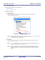
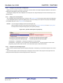
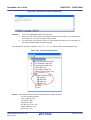
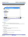
2.3.3
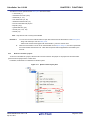
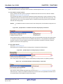
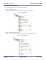
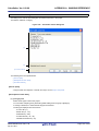
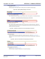
Remove a file from a project
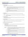
To remove a file added to a project, select the file to be removed from the project on the project tree and then select
[Remove from Project] from the context menu.
In addition, the file itself is not deleted from the file system.
Figure 2-11. [Remove from Project] Item
R20UT0555EJ0100 Rev.1.00
Apr 01, 2011
Page 23 of 570
CubeSuite+ Ver.1.00.00
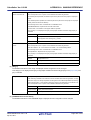
2.3.4
CHAPTER 2 FUNCTIONS
Remove a file from the build target
You can remove a specific file from the build target out of all the files added to the project.
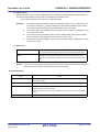
Select the file to be removed from the build target on the project tree and select the [Build Settings] tab on the Property
panel. Select [No] on the [Set as build-target] property in the [Build] category.
Figure 2-12. [Set as build-target] Property
Remark
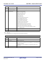
The files that can be applied this function are C source files, assembler source files, link directive files,
variables information files, function information file, object files, and library files.
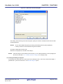
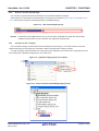
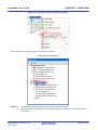
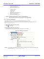
2.3.5
Classify a file into a category
You can create a category under the File node and classify files by the category. This makes it easier to view files
added to the project on the project tree, and makes it easier to manage files according to function.
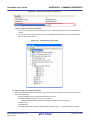
To create a category node, select either one of the Project node, Subproject node, or File node on the project tree, and
then select [Add] >> [Add New Category] from the context menu.
Figure 2-13. [Add New Category] Item (For File Node)
Figure 2-14. Project Tree Panel (After Adding Category Node)
R20UT0555EJ0100 Rev.1.00
Apr 01, 2011
Page 24 of 570
CubeSuite+ Ver.1.00.00
Remarks 1.
CHAPTER 2 FUNCTIONS
The default category name is "New category".
To change the category name, you can use [Rename] from the context menu of the category node.
2.
You can also add a category node with the same name as an existing category node.
3.
Categories can be nested up to 20 levels.
You can classify files into the created category node by dragging and dropping the file.
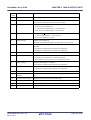
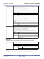
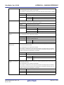
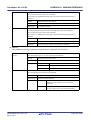
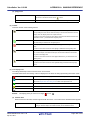
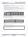
2.3.6
Change the file display order
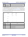
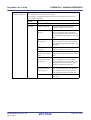
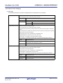
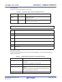
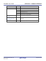
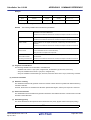
You can change the display order of the files and category nodes using the buttons on the project tree.
Figure 2-15. Toolbar (Project Tree Panel)
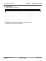
Select any of the buttons below on the toolbar of the Project Tree panel.
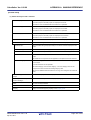
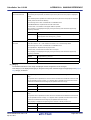
Button
Description
Sorts category nodes and files by name.
: Ascending order
: Descending order
: Ascending order
Sorts category nodes and files by timestamp.
: Descending order
: Ascending order
: Descending order
Displays category nodes and files in the specified order by the user (default).
You can change the display order of the category nodes and files arbitrarily by dragging and dropping
them.
R20UT0555EJ0100 Rev.1.00
Apr 01, 2011
Page 25 of 570
CubeSuite+ Ver.1.00.00
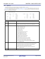
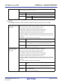
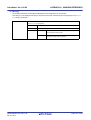
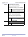
2.3.7
CHAPTER 2 FUNCTIONS
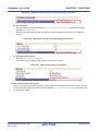
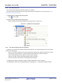
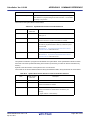
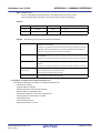
Update file dependencies
When you perform a change (changing include file paths, adding an include statement of the header file to the C source
file and assembler source file, etc.) that effects the file dependencies in the compile option settings or assemble option
settings, you must update the dependencies of the relevant files.
Updating file dependencies is performed for the entire project (main project and subprojects) or active project.
(1) For the entire project
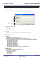
From the [Build] menu, select [Update Dependencies].
Figure 2-16. [Update Dependencies] Item
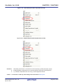
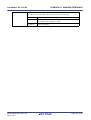
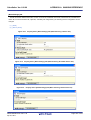
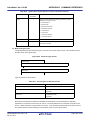
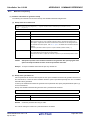
(2) For the active project
From the [Build] menu, select [Update Dependencies of active project].
R20UT0555EJ0100 Rev.1.00
Apr 01, 2011
Page 26 of 570
CubeSuite+ Ver.1.00.00
CHAPTER 2 FUNCTIONS
Figure 2-17. [Update Dependencies of active project] Item
Remark
If there are files being edited with the Editor panel when updating file dependencies, then all these files are
saved.
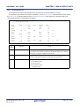
Cautions 1.
During checking of dependence relationships of include files with CubeSuite+, condition
statements such as #if and comments are ignored. Therefore, include files not required for
build are mistaken as required files (In the example below, header1.h and header5.h are judged
as required for build).
#if
0
#include
"header1.h"
#else
#include
/* Dependence relationship judged to exist */
/* ! zero */
"header2.h"
/* Dependence relationship to exist */
#endif
#define
AAA
#ifdef
AAA
#include
"header3.h"
/* Dependence relationship to exist */
"header4.h"
/* Dependence relationship to exist */
"header5.h"
/* Dependence relationship judged to exist */
#else
#include
#endif
/*
#include
*/
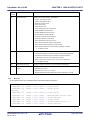
2.
During checking of dependence relationships of include files with CubeSuite+, include
statements described after comments are ignored. Therefore, include files required for build
R20UT0555EJ0100 Rev.1.00
Apr 01, 2011
Page 27 of 570
CubeSuite+ Ver.1.00.00
CHAPTER 2 FUNCTIONS
are mistaken as no-required files (In the example below, header6.h and header7.h are judged as
no-required for build).
/* Dependence relationship judged not to exist */
/* comment */
#include
"header6.h"
/* Dependence relationship judged not to exist */
/*
comment
*/
#include
R20UT0555EJ0100 Rev.1.00
Apr 01, 2011
"header7.h"
Page 28 of 570
CubeSuite+ Ver.1.00.00
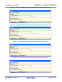
2.4
CHAPTER 2 FUNCTIONS
Set the Type of the Output File
Set the type of the file to be output as the product of the build.
Select the build tool node on the project tree and select the [Common Options] tab on the Property panel. Select the
file type on the [Output file type] property in the [Output File Type and Path] category.
Figure 2-18. [Output file type] Property
(1) When [Execute Module(Load Module File)] is selected (default)
A load module file is created.
The file set in the [Output File] category on the [Link Options] tab is the debug target.
(2) When [Execute Module(Hex File)] is selected
A hex file is also created.
The file set in the [Hex File] category on the [Object Convert Options] tab is the debug target.
Caution
2.4.1
For library projects, this property is always [Library] and cannot be changed.
Change the output file name
The names of the load module file, hex file, and library file output by the build tool are set to the following names by
default.
"%ProjectName%" is an embedded macro. It is replaced to the project name.
Load module file name: %ProjectName%.lmf
Hex file name: %ProjectName%.hex
Library file name: %ProjectName%.lib
The method to change these file names is shown below.
(1) When changing the load module file name
Select the build tool node on the project tree and select the [Link Options] tab on the Property panel. Enter the file
name to be changed to on the [Output file name] property in the [Output File] category.
Figure 2-19. [Output file name] Property (For Load Module File)
Remark
You can also change the option in the same way with the [Output file name] property in the [Frequently
Used Options(for Link)] category on the [Common Options] tab.
R20UT0555EJ0100 Rev.1.00
Apr 01, 2011
Page 29 of 570
CubeSuite+ Ver.1.00.00
CHAPTER 2 FUNCTIONS
(2) When changing the hex file name
Select the build tool node on the project tree and select the [Object Convert Options] tab on the Property panel.
Enter the file name to be changed to on the [Hex file name] property in the [Hex File] category.
Figure 2-20. [Hex file name] Property
Caution
When [Yes(-zf)] on the [Split hex file] property is selected, the hex file is split into separate files:
.hxb and .hxf. If a code is output to a segment allocated in extended space, a separate hex file
(.H1 to .H15) is output into each space.
See "B.4.2 Functions" for details.
Remark
You can also change the option in the same way with the [Hex file name] property in the [Frequently
Used Options(for Object Convert)] category on the [Common Options] tab.
(3) When changing the library file name
Select the build tool node on the project tree and select the [Create Library Options] tab on the Property panel.
Enter the file name to be changed to on the [Output file name] property in the [Output File] category.
Figure 2-21. [Output file name] Property (For Library File)
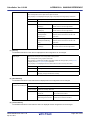
2.4.2
Output an assemble list
The results of the assembly are output to the assembler list file.
Select the build tool node on the project tree and select the [Assemble Options] tab on the Property panel. To output
the assemble list, select [Yes(-p)] (default) on the [Output assemble list file] property in the [Assemble List] category.
Figure 2-22. [Output assemble list file] Property
Remarks 1.
See "3.2.2 Assemble list" for the assemble list.
R20UT0555EJ0100 Rev.1.00
Apr 01, 2011
Page 30 of 570
CubeSuite+ Ver.1.00.00
2.
CHAPTER 2 FUNCTIONS
If you select [No(-np)] on the [Output assemble list file] property when performing assembly only to
output an object module file, you can reduce the assembly time.
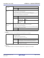
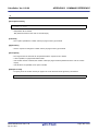
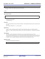
2.4.3
Output map information
Map information (information on the location of segments) is output to the link list file.
Select the build tool node on the project tree and select the [Link Options] tab on the Property panel. The setting to
output a link list file is made with the [Link List] category.
Figure 2-23. [Link List] Category (For Map Information)
If you select [Yes] (default) on the [Output link list file] property, the [Output with map list] property is displayed. To
output map information to the link list file, select [Yes] (default).
Remark
2.4.4
See "3.3.2 Map list" for map information.
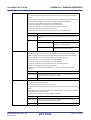
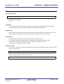
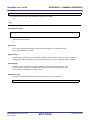
Output symbol information
Symbol information (local symbols and public symbols) defined in the input module is output to the link list file. Select
the build tool node on the project tree and select the [Link Options] tab on the Property panel.
The setting to output symbol information is made with the [Link List] category.
(1) When outputting the local symbol list
Figure 2-24. [Link List] Category (For Local Symbol Information)
If you select [Yes] (default) on the [Output link list file] property, the [Output with local symbol list] property is
displayed. To output local symbol list to the link list file, select [Yes(-kl)] ([No] is selected by default).
Remark
See "3.3.4 Local symbol list" for the local symbol list.
R20UT0555EJ0100 Rev.1.00
Apr 01, 2011
Page 31 of 570
CubeSuite+ Ver.1.00.00
CHAPTER 2 FUNCTIONS
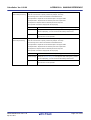
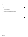
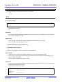
(2) When outputting the public symbol list
Figure 2-25. [Link List] Category (For Public Symbol Information)
If you select [Yes] (default) on the [Output link list file] property, the [Output with public symbol list] property is
displayed. To output public symbol list to the link list file, select [Yes(-kp)] ([No] is selected by default).
Remark
See "3.3.3 Public symbol list" for the public symbol list.
R20UT0555EJ0100 Rev.1.00
Apr 01, 2011
Page 32 of 570
CubeSuite+ Ver.1.00.00
2.5
CHAPTER 2 FUNCTIONS
Set Compile Options
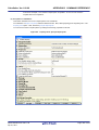
To set options for the compiler, select the Build tool node on the project tree and select the [Compile Options] tab on the
Property panel.
You can set the various compile options by setting the necessary properties in this tab.
Figure 2-26. Property Panel: [Compile Options] Tab
Remark
Often used options have been gathered under the [Frequently Used Options(for Compile)] category on the
[Common Options] tab.
R20UT0555EJ0100 Rev.1.00
Apr 01, 2011
Page 33 of 570
CubeSuite+ Ver.1.00.00
2.5.1
CHAPTER 2 FUNCTIONS
Perform optimization with the code size precedence
Select the build tool node on the project tree and select the [Compile Options] tab on the Property panel.
To perform optimization with the code size precedence, select [Yes(Code size)(-qx3)] or [Yes(Code size (Best))(-qx4)]
on the [Perform optimization] property in the [Optimization] category ([No] is selected by default).
If you select [Yes(Code size (Best))(-qx4)], then addition to the settings of [Yes(Code size)(-qx3)], common code is
placed in subroutines, and the library for the stack access is used.
Figure 2-27. [Perform optimization] Property (Code Size Precedence)
Remark
You can also set the option in the same way with the [Perform optimization] property in the [Frequently Used
Options(for Compile)] category on the [Common Options] tab.
2.5.2
Perform optimization with the execution speed precedence
Select the build tool node on the project tree and select the [Compile Options] tab on the Property panel.
To perform optimization with the execution speed precedence, select [Yes(Speed precedence)(-qx1)] on the [Perform
optimization] property in the [Optimization] category ([No] is selected by default).
Figure 2-28. [Perform optimization] Property (Execution Speed Precedence)
Remark
You can also set the option in the same way with the [Perform optimization] property in the [Frequently Used
Options(for Compile)] category on the [Common Options] tab.
2.5.3
Add an include path
Select the build tool node on the project tree and select the [Compile Options] tab on the Property panel.
The include path setting is made with the [Additional include paths] property in the [Preprocess] category.
Figure 2-29. [Additional include paths] Property
If you click the [...] button, the Path Edit dialog box will open.
R20UT0555EJ0100 Rev.1.00
Apr 01, 2011
Page 34 of 570
CubeSuite+ Ver.1.00.00
CHAPTER 2 FUNCTIONS
Figure 2-30. Path Edit Dialog Box
Enter an include path per line in [Path(One path per one line)]. You can specify up to 259 characters per line, up to 64
line.
Remark
You can also specify the include path by dragging and dropping from Explorer or the like, or by the
[Browse...] button. Select the [Subfolders are automatically included] check box before clicking the
[Browse...] button to add all paths under the specified one (down to 5 levels) to [Path(One path per one
line)].
If you click the [OK] button, the entered include paths are displayed as subproperties.
Figure 2-31. [Additional include paths] Property (After Adding Include Paths)
To change the include paths, you can use the [...] button or enter the path directly in the text box of the subproperty.
When the include path is added to the project tree, the path is added to the top of the subproperties automatically.
Remark
You can also set the option in the same way with the [Additional include paths] property in the [Frequently
Used Options(for Compile)] category on the [Common Options] tab.
R20UT0555EJ0100 Rev.1.00
Apr 01, 2011
Page 35 of 570
CubeSuite+ Ver.1.00.00
2.5.4
CHAPTER 2 FUNCTIONS
Set a macro definition
Select the build tool node on the project tree and select the [Compile Options] tab on the Property panel.
The macro definition setting is made with the [Macro definition] property in the [Preprocess] category.
Figure 2-32. [Macro definition] Property
If you click the [...] button, the Text Edit dialog box will open.
Figure 2-33. Text Edit Dialog Box
Enter the macro definition in the format of "macro name=defined value", with one macro name per line. You can
specify up to 256 characters per line, up to 30 line. The "=defined value" part can be omitted, and in this case, "1" is used
as the defined value.
If you click the [OK] button, the entered macro definitions are displayed as subproperties.
Figure 2-34. [Macro definition] Property (After Setting Macros)
To change the macro definitions, you can use the [...] button or enter the path directly in the text box of the subproperty.
Remark
You can also set the option in the same way with the [Macro definition] property in the [Frequently Used
Options(for Compile)] category on the [Common Options] tab.
R20UT0555EJ0100 Rev.1.00
Apr 01, 2011
Page 36 of 570
CubeSuite+ Ver.1.00.00
2.5.5
CHAPTER 2 FUNCTIONS
Enable C++ comments
Select the build tool node on the project tree and select the [Compile Options] tab on the Property panel.
To enable C++ comments, select [Yes(-zp)] on the [Allow C++ format comments] property in the [Extension] category
(default).
Figure 2-35. [Allow C++ format comments] Property
2.5.6
Use floating point-compatible standard input/output functions
Select the build tool node on the project tree and select the [Compile Options] tab on the Property panel.
In the [Library] category, if you select [Yes] on the [Use standard library] property, the [Use standard I/O library
supported floating-point data] property is displayed. To use the standard input/output functions which support floatingpoint data (sprintf, sscanf, printf, vprintf, and vsprintf), select [Yes].
Figure 2-36. [Use standard library] and [Use standard I/O library supported floating-point data] Property
2.5.7
Change the setting to use the multiplier and divider
Select the build tool node on the project tree and select the [Compile Options] tab on the Property panel.
In the [Library] category, if you select [Yes] on the [Use standard library] property, the [Use multiplier and divider]
property is displayed. When using a standard library which supports the multiplier and divider, select [Yes] (default),
when not using one, select [No].
Figure 2-37. [Use standard library] and [Use multiplier and divider] Property
R20UT0555EJ0100 Rev.1.00
Apr 01, 2011
Page 37 of 570
CubeSuite+ Ver.1.00.00
2.6
CHAPTER 2 FUNCTIONS
Set Assemble Options
To set options for the assembler, select the Build tool node on the project tree and select the [Assemble Options] tab on
the Property panel.
You can set the various assemble options by setting the necessary properties in this tab.
Figure 2-38. Property Panel: [Assemble Options] Tab
Remark
Often used options have been gathered under the [Frequently Used Options(for Assemble)] category on the
[Common Options] tab.
2.6.1
Add an include path
Select the build tool node on the project tree and select the [Assemble Options] tab on the Property panel.
The include path setting is made with the [Additional include paths] property in the [Preprocess] category.
Figure 2-39. [Additional include paths] Property
If you click the [...] button, the Path Edit dialog box will open.
R20UT0555EJ0100 Rev.1.00
Apr 01, 2011
Page 38 of 570
CubeSuite+ Ver.1.00.00
CHAPTER 2 FUNCTIONS
Figure 2-40. Path Edit Dialog Box
Enter an include path per line in [Path(One path per one line)]. You can specify up to 259 characters per line, up to 64
line.
Remark
You can also specify the include path via the [Browse...] button. Select the [Subfolders are automatically
included] check box before clicking the [Browse...] button to add all paths under the specified one (down to
5 levels) to [Path(One path per one line)].
If you click the [OK] button, the entered include paths are displayed as subproperties.
Figure 2-41. [Additional include paths] Property (After Adding Include Paths)
To change the include paths, you can use the [...] button or enter the path directly in the text box of the subproperty.
When the include path is added to the project tree, the path is added to the top of the subproperties automatically.
Remark
You can also set the option in the same way with the [Additional include paths] property in the [Frequently
Used Options(for Assemble)] category on the [Common Options] tab.
R20UT0555EJ0100 Rev.1.00
Apr 01, 2011
Page 39 of 570
CubeSuite+ Ver.1.00.00
2.6.2
CHAPTER 2 FUNCTIONS
Set a macro definition
Select the build tool node on the project tree and select the [Assemble Options] tab on the Property panel.
The macro definition setting is made with the [Macro definition] property in the [Preprocess] category.
Figure 2-42. [Macro definition] Property
If you click the [...] button, the Text Edit dialog box will open.
Figure 2-43. Text Edit Dialog Box
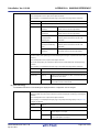
Enter the macro definition in the format of "macro name=defined value", with one macro name per line. You can
specify up to 31 characters per line, up to 30 line. The "=defined value" part can be omitted, and in this case, "1" is used
as the defined value.
If you click the [OK] button, the entered macro definitions are displayed as subproperties.
Figure 2-44. [Macro definition] Property (After Setting Macros)
To change the macro definitions, you can use the [...] button or enter the path directly in the text box of the subproperty.
Remark
You can also set the option in the same way with the [Macro definition] property in the [Frequently Used
Options(for Assemble)] category on the [Common Options] tab.
R20UT0555EJ0100 Rev.1.00
Apr 01, 2011
Page 40 of 570
CubeSuite+ Ver.1.00.00
2.7
CHAPTER 2 FUNCTIONS
Set Link Options
To set options for the linker, select the Build tool node on the project tree and select the [Link Options] tab on the
Property panel.
You can set the various link options by setting the necessary properties in this tab.
Caution
This tab is not displayed for library projects.
Figure 2-45. Property Panel: [Link Options] Tab
Remark
Often used options have been gathered under the [Frequently Used Options(for Link)] category on the
[Common Options] tab.
R20UT0555EJ0100 Rev.1.00
Apr 01, 2011
Page 41 of 570
CubeSuite+ Ver.1.00.00
2.7.1
CHAPTER 2 FUNCTIONS
Add a user library
Select the build tool node on the project tree and select the [Link Options] tab on the Property panel.
Adding a user library is made with the [Using libraries] property in the [Library] category.
Figure 2-46. [Using libraries] Property
If you click the [...] button, the Text Edit dialog box will open.
Figure 2-47. Text Edit Dialog Box
Enter the library file name in [Text] with one name per line. You can specify up to 259 characters per line, up to 64 line.
If you click the [OK] button, the entered library files are displayed as subproperties.
Figure 2-48. [Using libraries] Property (After Setting Library Files)
To change the library files, you can use the [...] button or enter the path directly in the text box of the subproperty.
Remark
You can also set the option in the same way with the [Using libraries] property in the [Frequently Used
Options(for Link)] category on the [Common Options] tab.
The library files are searched from the library path. To add a library path, set the [Additional library paths] property.
Caution
Library files can also be linked by adding them directly to the project. In this case, the library files
are not searched from the library paths because they are linked directly via their absolute paths.
R20UT0555EJ0100 Rev.1.00
Apr 01, 2011
Page 42 of 570
CubeSuite+ Ver.1.00.00
2.8
CHAPTER 2 FUNCTIONS
Set Object Convert Options
To set options for the object converter, select the Build tool node on the project tree and select the [Object Convert
Options] tab on the Property panel.
You can set the various object convert options by setting the necessary properties in this tab.
Caution
This tab is not displayed for library projects.
Figure 2-49. Property Panel: [Object Convert Options] Tab
Remark
Often used options have been gathered under the [Frequently Used Options(for Object Convert)] category
on the [Common Options] tab.
R20UT0555EJ0100 Rev.1.00
Apr 01, 2011
Page 43 of 570
CubeSuite+ Ver.1.00.00
2.8.1
CHAPTER 2 FUNCTIONS
Set the output of a hex file
Select the build tool node on the project tree and select the [Object Convert Options] tab on the Property panel.
The setting to output a hex file is made with the [Output hex file] property in the [Hex File] category. To output a hex file,
select [Yes] (default), to not output a hex file, select [No(-no)].
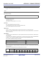
Figure 2-50. [Output hex file] Property
Remark
If you select [No(-no)] on the [Output hex file] property when performing object conversion only to output a
symbol table file, you can reduce the object conversion time.
When outputting a hex file, you can set the output folder and output file name.
(1) Set the output folder
Setting the output folder is made with the [Output folder for hex file] property by directly entering to the text box or
by the [...] button. Up to 259 characters can be specified in the text box. "%BuildModeName%" is set by default.
"%BuildModeName%" is an embedded macro. It is replaced to the build mode name.
(2) Set the output file name
Setting the output file is made with the [Hex file name] property by directly entering to the text box. Up to 259
characters can be specified in the text box. "%ProjectName%.hex" is set by default. "%ProjectName%.hex" is an
embedded macro. It is replaced to the project name.
R20UT0555EJ0100 Rev.1.00
Apr 01, 2011
Page 44 of 570
CubeSuite+ Ver.1.00.00
2.9
CHAPTER 2 FUNCTIONS
Set Create Library Options
To set options for the librarian, select the Build tool node on the project tree and select the [Create Library Options] tab
on the Property panel.
You can set the various create library options by setting the necessary properties in this tab.
Caution
This tab is displayed only for library projects.
Figure 2-51. Property Panel: [Create Library Options] Tab
2.9.1
Set the output of a library file
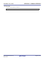
Select the build tool node on the project tree and select the [Create Library Options] tab on the Property panel.
The setting to output a library file is made with the [Output File] category.
Figure 2-52. [Output File] Category
(1) Set the output folder
Setting the output folder is made with the [Output folder] property by directly entering to the text box or by the [...]
button. Up to 259 characters can be specified in the text box. "%BuildModeName%" is set by default.
"%BuildModeName%" is an embedded macro. It is replaced to the build mode name.
(2) Set the output file name
Setting the output file is made with the [Output file name] property by directly entering to the text box. Up to 259
characters can be specified in the text box. "%ProjectName%.lib" is set by default. "%ProjectName%.lib" is an
embedded macro. It is replaced to the project name.
R20UT0555EJ0100 Rev.1.00
Apr 01, 2011
Page 45 of 570
CubeSuite+ Ver.1.00.00
2.10
CHAPTER 2 FUNCTIONS
Set Variables Relocation Options
To set options for the variables information file generator, select the Build tool node on the project tree and select the
[Variables Relocation Options] tab on the Property panel.
You can set the various variables relocation options by setting the necessary properties in this tab.
Figure 2-53. Property Panel: [Variables Relocation Options] Tab
2.10.1
Efficiently allocate variables
Use the variables information file generator to efficiently allocate variables. This tool generates a variables information
file (a file containing allocation information for all variables to be referenced). Variables will be allocated to the saddr area
by performing compilation using that file.
The procedures for performing this operation are described below.
- Generating a variables information file automatically and allocating variables and functions
- Editing and using an auto-generated variables information file
(1) Generating a variables information file automatically and allocating variables and functions
Below is the procedure for generating a variables/functions information file automatically and using that file to
allocate variables and functions, via one build.
(a) Set the generation of the variables information file
Select the build tool node on the project tree and select the [Variables Relocation Options] tab on the Property
panel.
Set the [Output variables information file] property to [Yes] to generate an empty variables information file, and
add it to the project (it will also appear in the File node of the project tree). The output destination is the file set
in the [Output folder for variables information file] property and the [Variables information file name] property.
Remark
If a variables information file with the same name already exists, the build will be configured to use
it.
R20UT0555EJ0100 Rev.1.00
Apr 01, 2011
Page 46 of 570
CubeSuite+ Ver.1.00.00
CHAPTER 2 FUNCTIONS
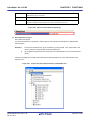
Figure 2-54. [Output variables information file] Property
Figure 2-55. Project Tree Panel (After Generating Variables Information File)
The settings of the output folder and file of the variables information file are can be changed.
<1> Set the output folder
Setting the output folder is made with the [Output folder for variables information file] property by directly
entering to the text box or by the [...] button. Up to 259 characters can be specified in the text box.
"%BuildModeName%" is set by default. "%BuildModeName%" is an embedded macro. It is replaced to
the build mode name.
If this property is changed, an empty variables information file is generated and added to the project (it
will also appear in the File node of the project tree).
<2> Set the output file name
Setting the output file is made with the [Variables information file name] property by directly entering to
the text box. Up to 259 characters can be specified in the text box. "%ProjectName%.vfi" is set by
default. "%ProjectName%.vfi" is an embedded macro. It is replaced to the project name.
If this property is changed, an empty variables information file is generated and added to the project (it
will also appear in the File node of the project tree).
(b) Run a build of the project
Run a build of the project.
A variables information file is generated. It will be input into the compiler automatically and a rebuild will be
executed again.
Remark
The variables information file in "(a) Set the generation of the variables information file" is
overwritten by running a build.
R20UT0555EJ0100 Rev.1.00
Apr 01, 2011
Page 47 of 570
CubeSuite+ Ver.1.00.00
CHAPTER 2 FUNCTIONS
If the build completes successfully, a load module file is generated with the variables allocated.
If the message "E7001 : The link error was found." is displayed at this time, then an error has occurred during
linking.
If this happens, take the action below to disable the variable information file.
<1> Select [No] in the [Output variables information file] property on the [Variables Relocation
Options] tab.
<2> Select [No] on the [Set as build-target] property of the variables information file (*.vfi) displayed
on the project tree.
Or select the variables information file and select [Remove from Project] from the context menu.
Figure 2-56. Project Tree Panel (After Generating Load Module File)
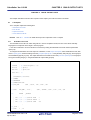
(2) Editing and using an auto-generated variables information file
Users can edit a variables information file.
Below is the procedure for editing the generated variables information file in "(1) Generating a variables
information file automatically and allocating variables and functions" by the user and using that file to allocate
variables.
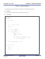
(a) Edit the variables information file
Edit the variables information file generated automatically in "(1) Generating a variables information file
automatically and allocating variables and functions".
Remark
See "3.7.1 Variables information file" for details about the format of the auto-generated variables
information file.
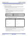
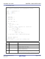
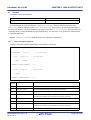
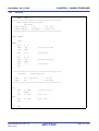
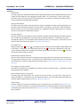
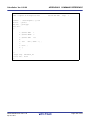
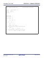
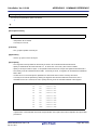
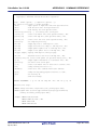
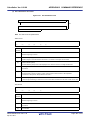
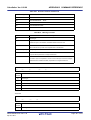
Describe the variables information file according to the following format.
R20UT0555EJ0100 Rev.1.00
Apr 01, 2011
Page 48 of 570
CubeSuite+ Ver.1.00.00
CHAPTER 2 FUNCTIONS
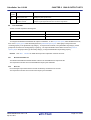
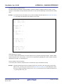
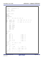
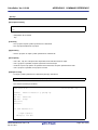
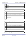
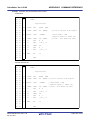
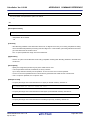
;***Variable information***
;static variable and const variable
variable-name,number-of-references,size,reference-type,"file-name",const
;global variable and const variable
variable-name,number-of-references,size,reference-type,,const
;static variable
variable-name,number-of-references,size,reference-type,"file-name"
;global variable
variable-name,number-of-references,size,reference-type
;global variable and const variable for the boot area
variable-name,number-of-references,size,reference-type,,const,boot
;global variable for the boot area
variable-name,number-of-references,size,reference-type,,,boot
Remark
Describe variables in the order of priority, from highest to lowest.
Comment out the lines for variables and functions that are not to be allocated by adding a
semicolon (;) at the beginning of the line.
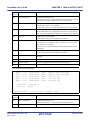
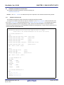
(b) Set the generation of the variables information file
Select the build tool node on the project tree and select the [Variables Relocation Options] tab on the Property
panel.
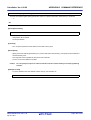
Select [No] on the [Output variables information file] property.
Figure 2-57. [Output variables information file] Property
(c) Run a build of the project
Run a build of the project.
A load module file is generated with the variables allocated as specified in the variables information file.
Caution
If a file with an extension of "vfi" is added to the project, it is treated as a variables information file.
It is also treated as a variables information file if it is added below the Startup node.
When adding a variables information file to the project, if a variables information file has already
been added then only the latest variables information file to be added is targeted by a build; any
such files added prior to this one will not be targeted.
When setting a variables information file that is not targeted by a build as a build target, if other
variables information files have also been added then the file will be targeted by the build, and the
others will not be targeted.
R20UT0555EJ0100 Rev.1.00
Apr 01, 2011
Page 49 of 570
CubeSuite+ Ver.1.00.00
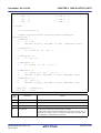
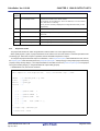
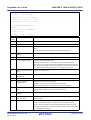
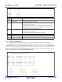
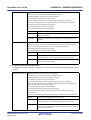
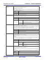
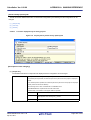
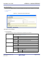
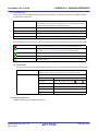
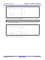
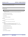
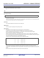
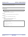
2.10.2
CHAPTER 2 FUNCTIONS
Display ROM/RAM usage
You can use the variables information file generator to display the ROM/RAM usage after the linking to the Output
panel.
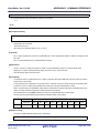
Select the build tool node on the project tree and select the [Variables Relocation Options] tab on the Property panel.
To display the ROM/RAM usage, select [Yes] on the [Output ROM/RAM usage] property in the [ROM/RAM Amount
Information] category ([No] is selected by default).
Figure 2-58. [Output ROM/RAM usage] Property
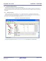
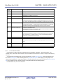
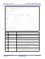
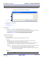
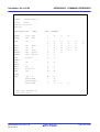
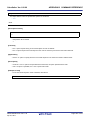
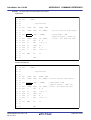
When you run a build, the ROM/RAM usage is output to the Output panel following the build results.
First the total amount uses is output, followed by the usage for each memory area.
Figure 2-59. ROM/RAM Usage Display
R20UT0555EJ0100 Rev.1.00
Apr 01, 2011
Page 50 of 570
CubeSuite+ Ver.1.00.00
2.11
CHAPTER 2 FUNCTIONS
Set Memory Bank Relocation Options
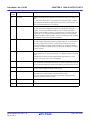
To set options for the memory bank relocation support tool, select the Build tool node on the project tree and select the
[Memory Bank Relocation Options] tab on the Property panel.
You can set the various memory bank relocation options by setting the necessary properties in this tab.
Figure 2-60. Property Panel: [Memory Bank Relocation Options] Tab
2.11.1
Relocate C source files to the optimum area
Use the memory bank relocation support tool to relocate C source files to the optimum area. This tool generates a
function information file (a file containing relocation information for each file). C source files will be relocated to the
common area or bank area by performing compilation using that file.
Caution
This function is valid only when a device with a memory bank installed is specified as the
microcontroller.
The procedures for performing this operation are described below.
- Generating a function information file automatically and relocating C source files
- Changing the relocation destination of the auto-generated function information file
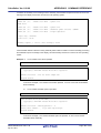
(1) Generating a function information file automatically and relocating C source files
Below is the procedure for generating a function information file automatically and using that file to relocate C
source files, via one build.
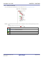
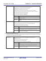
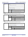
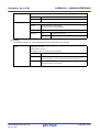
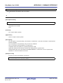
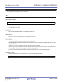
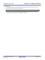
(a) Set the output of the function information file
Select the build tool node on the project tree and select the [Memory Bank Relocation Options] tab on the
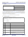
Property panel. To use the memory bank relocation support tool, select [Yes] on the [Use memory bank
relocation support tool] property in the [Output] category ([No] is selected by default).
R20UT0555EJ0100 Rev.1.00
Apr 01, 2011
Page 51 of 570
CubeSuite+ Ver.1.00.00
CHAPTER 2 FUNCTIONS
Figure 2-61. [Use memory bank relocation support tool] Property
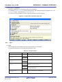
Remark
If you select [Yes] on the [Use memory bank relocation support tool] property, the following
properties are automatically changed.
- The [Add debug information] property in the [Debug Information] category from the [Compile
Options] tab will be changed to [Yes(Add to both assembly and object file)(-g2)].
- The [Output assemble file] property in the [Assembly File] category from the [Compile Options] tab
will be changed to [Yes(With no C source info)(-a)].
- The [Output assemble list file] property in the [Assemble List] category from the [Assemble Options]
tab will be changed to [Yes(-p)].
- The [Output with cross reference list] property in the [Assemble List] category from the [Assemble
Options] tab will be changed to [Yes(-kx)].
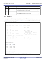
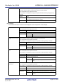
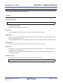
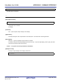
Set the [Output function information file] property to [Yes] to generate an empty function information file, and
add it to the project (it will also appear in the Files node of the project tree). The output destination is the file
set in the [Output folder for function information file] property and the [Function information file name] property.
Remark
If a function information file with the same name already exists, the build will be configured to use it.
Figure 2-62. [Output function information file] Property
R20UT0555EJ0100 Rev.1.00
Apr 01, 2011
Page 52 of 570
CubeSuite+ Ver.1.00.00
CHAPTER 2 FUNCTIONS
Figure 2-63. Project Tree Panel (After Generating Function Information File)
The settings of the output folder and file of the function information file are can be changed.
<1> Set the output folder
Setting the output folder is made with the [Output folder for function information file] property by directly
entering to the text box or by the [...] button. Up to 259 characters can be specified in the text box.
"%BuildModeName%" is set by default. "%BuildModeName%" is an embedded macro. It is replaced to
the build mode name.
<2> Set the output file name
Setting the output file is made with the [Function information file name] property by directly entering to
the text box. Up to 259 characters can be specified in the text box. "%ProjectName%.fin" is set by
default. "%ProjectName%" is an embedded macro. It is replaced to the project name.
If this property is changed, an empty function information file is generated and added to the project (it will
also appear in the Files node of the project tree).
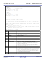
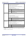
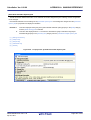
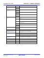
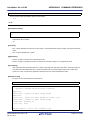
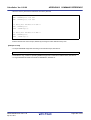
(b) Set the output of auxiliary information files
Set the output of auxiliary information files, which provide support when the user edits the generated function
information file.
The auxiliary information files are as follows.
- Replacement information file
- Object information file
- Reference information file
Remark
See "3.8 Memory Bank Relocation Support Tool" for details about each file.
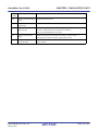
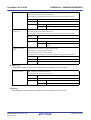
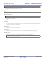
The setting to output auxiliary files is made with the [Output File] category.
R20UT0555EJ0100 Rev.1.00
Apr 01, 2011
Page 53 of 570
CubeSuite+ Ver.1.00.00
CHAPTER 2 FUNCTIONS
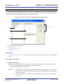
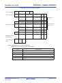
Figure 2-64. [Output File] Category
Set the output folder and output file name for each file on the [Output folder for replacement information file],
[Replacement information file name], [Output folder for object information file], [Object information file name],
[Output folder for reference information file], and [Reference information file name] properties.
Remark
Select [No] on the [Output function information file] property to output the auxiliary information files
only.
(c) Set the margin of the relocation destination
Set the margin for the common area or bank area to which the function information file will be relocated when
it is generated.
Set the margin in the [Margin] category.
Figure 2-65. [Margin] Category
Set the margin for the common area on the [Margin for common area] property in decimal numbers. The
range that can be specified for the value is -65536 to 65536 (default: 1000).
Set the margin for the bank area on the [Margin for bank XX area] property in decimal numbers. The range
that can be specified for the value is -65536 to 65536 (default: 500). This property is displayed corresponding
to the numbers of banks (XX: 00 to 15).
Remark
If a positive value is specified on the above property, each area is relocated and considered to
become small by the specified value as a margin. If a negative value is specified, each area is
relocated and considered to become large by the specified value as a margin.
(d) Set the relocation destination for each file
Specify the relocation destination for each C source file.
Select a C source file on the project tree and select the [Build Settings] tab on the project tree. Select the
relocation destination on the [Select common/bank area] property in the [Memory Bank] category.
You can select any of items below.
R20UT0555EJ0100 Rev.1.00
Apr 01, 2011
Page 54 of 570
CubeSuite+ Ver.1.00.00
No specification
CHAPTER 2 FUNCTIONS
The memory bank relocation support tool automatically determines the optimum area and
relocates the program code there.
Common area
Relocates the program codes to the common area in build processing.
BankXX
Relocates the program codes to bankXX in build processing.
This item is displayed corresponding to the numbers of banks (XX: 00 to 15).
Figure 2-66. [Select common/bank area] Property
(e) Run a build of the project
Run a build of the project.
A function information file is generated. It will be input into the compiler automatically and a rebuild will be
executed again.
Remarks 1.
The function information file in (a) is overwritten by running a build. If the output folder or file
name is changed, the specified file will be generated again.
2.
Since objects are generated anew using the function information file, the second build will be a
rebuild.
If the build completes successfully, a load module file is generated with the C source files relocated to the
specified area.
Figure 2-67. Project Tree Panel (After Generating Load Module File)
R20UT0555EJ0100 Rev.1.00
Apr 01, 2011
Page 55 of 570
CubeSuite+ Ver.1.00.00
CHAPTER 2 FUNCTIONS
(2) Changing the relocation destination of the auto-generated function information file
If a warning (W1402000) occurs while running a build in (1), you must change the relocation destination.
Below is the procedure for relocating the C source files after you have changed the relocation destination.
(a) Change the relocation destination
When changing the relocation destination, perform the actions while making reference to the auxiliary
information files (replacement information file, object information file, and reference information files).
The example of changing the relocation destination is shown below.
<1> If you could not relocate files containing functions that cannot be relocated to the common area
or bank area
Select files in the function information file defined for relocation to the common area (files with "C"
specified as the relocation destination) that can be relocated to the bank area, and change their
relocation destination to the bank area.
Whether the selected file can be relocated to the bank area can be identified by referring to the
replacement information file.
Files that can be relocated only to the
Files to which "*" is appended the end of "file name (code size)" in
common area
the replacement information file
Files that can be relocated to the
Files to which "*" is not appended the end of "file name (code size)"
common area and bank area
in the replacement information file
Example Change the relocation destination of file "file100.c" from the common area to bank 3, and that
of file "file200.c" from the common area to bank 4.
Before Change
After Change
:
:
file100.c := C (100)
file100.c := 3 (100)
{
{
file100;
file100;
}
}
file200.c := C (200)
file200.c := 4 (200)
{
{
file200;
file200;
}
}
:
:
<2> When the size of the vacant area is larger than that of the file that could not be relocated
The memory bank relocation support tool keeps some margin (by default, common area: 1000 bytes,
bank area: 500 bytes) during relocation process of files.
Consequently, the size of the vacant area may be larger than that of the file that could not be relocated,
in the replacement information files.
In this case, on the Property panel, from the [Memory Bank Relocation Options] tab, in the [Margin]
category, set the margins of the common area and bank area to smaller values.
R20UT0555EJ0100 Rev.1.00
Apr 01, 2011
Page 56 of 570
CubeSuite+ Ver.1.00.00
CHAPTER 2 FUNCTIONS
<3> When the total code size is larger than the ROM size
Reinforce the optimization by the C compiler and review the source program to reduce the total code
size.
Refer to the reference information file and take a relevant action if functions that satisfy the following
conditions are found.
- When the function is not referenced from other files
If the relevant function is the global function, change it to the static function.
- When the function is not referenced from other files nor from the file in which the function is
described
Delete the function.
Caution
The function for which above action be taken shall not be called in the implicit way
(such as an indirect function call using a function pointer or a call from object module
file/library file that do not have source files) which can not be known from assemble
list file.
(b) Set the output of the function information file
Select the build tool node on the project tree and select the [Memory Bank Relocation Options] tab on the
Property panel. To use the memory bank relocation support tool, select [Yes] on the [Use memory bank
relocation support tool] property in the [Output] category.
Select [No] on the [Output function information file] property.
Figure 2-68. [Use memory bank relocation support tool] and [Output function information file] Property
(c) Run a build of the project
Run a build of the project.
A load module file is generated with the C source files relocated in accordance with the changes made to the
relocation destinations.
Caution
If a file with an extension of "fin" is added to the project, it is treated as a function information file. It
is also treated as a function information file if it is added below the Startup node.
When adding a function information file to the project, if a functions information file has already
been added then only the latest function information file to be added is targeted by a build; any such
files added prior to this one will not be targeted.
When setting a function information file that is not targeted by a build as a build target, if other
function information files have also been added then the file will be targeted by the build, and the
others will not be targeted.
R20UT0555EJ0100 Rev.1.00
Apr 01, 2011
Page 57 of 570
CubeSuite+ Ver.1.00.00
2.12
CHAPTER 2 FUNCTIONS
Set Build Options Separately
Build options are set at the project or file level.
- Project level: See "2.12.1 Set build options at the project level"
- Project level: See "2.12.2 Set build options at the file level"
2.12.1
Set build options at the project level
To set options for build options for a project (main project or subproject), select the Build tool node on the project tree to
display the Property panel.
Select the component tabs, and set build options by setting the necessary properties.
Compiler: [Compile Options] tab
Assembler, List Converter: [Assemble Options] tab
Linker: [Link Options] tab
Object converter: [Object Convert Options] tab
Librarian: [Create Library Options] tab
Variables information file generator: [Variables Relocation Options] tab
Memory bank relocation support tool: [Memory Bank Relocation Options] tab
2.12.2
Set build options at the file level
You can individually set compile and assemble options for each source file added to the project.
(1) When setting compile options for a C source file
Select a C source file on the project tree and select the [Build Settings] tab on the Property panel. In the [Build]
category, if you select [Yes] on the [Set individual compile option] property, the message dialog box ("Figure 2-70.
Message Dialog Box") is displayed.
Figure 2-69. [Set individual compile option] Property
Figure 2-70. Message Dialog Box
If you click the [Yes] button in the dialog box, the [Individual Compile Options] tab will be displayed.
R20UT0555EJ0100 Rev.1.00
Apr 01, 2011
Page 58 of 570
CubeSuite+ Ver.1.00.00
CHAPTER 2 FUNCTIONS
Figure 2-71. Property Panel: [Individual Compile Options] Tab
You can set compile options for the C source file by setting the necessary properties in this tab. Note that this tab
takes over the settings of the [Compile Options] tab by default.
(2) When setting assemble options for an assembler source file
Select an assembler source file on the project tree and select the [Build Settings] tab on the Property panel. In the
[Build] category, if you select [Yes] on the [Set individual assemble option] property, the message dialog box
("Figure 2-73. Message Dialog Box") is displayed.
Figure 2-72. [Set individual assemble option] Property
Figure 2-73. Message Dialog Box
R20UT0555EJ0100 Rev.1.00
Apr 01, 2011
Page 59 of 570
CubeSuite+ Ver.1.00.00
CHAPTER 2 FUNCTIONS
If you click the [Yes] button in the dialog box, the [Individual Assemble Options] tab will be displayed.
Figure 2-74. Property Panel: [Individual Assemble Options] Tab
You can set assemble options for the assembler source file by setting the necessary properties in this tab. Note
that this tab takes over the settings of the [Assemble Options] tab by default.
Remark
You can also set assemble options for assembler source files created from C source files. Select a C
source file on the project tree and select the [Individual Compile Options] tab on the Property panel. If
you select [Yes] on the [Output assemble file] property in the [Assembly File] category, the [Individual
Assemble Options] tab is displayed.
R20UT0555EJ0100 Rev.1.00
Apr 01, 2011
Page 60 of 570
CubeSuite+ Ver.1.00.00
2.13
CHAPTER 2 FUNCTIONS
Prepare for Using On-chip Debugger
To use the on-chip debugger, you must set the on-chip debug, user option byte, and security ID.
(1) Setting the on-chip debug
The on-chip debug function of the microcontroller is enabled by setting the on-chip debug.
Select the build tool node on the project tree and select the [Link Options] tab on the Property panel. Set the onchip debug in the [Device] category.
If you select [Yes(-go)] on the [Use on-chip debug] property, the [Debug monitor area size[byte]] property are
displayed.
Figure 2-75. [Use on-chip debug] and [Debug monitor area size[byte]] Property
On the [Debug monitor area size[byte]] property, specify the size of the debug monitor area in decimal. The range
that can be specified for the value is 256 to 1024 (default: 256).
(2) Set the user option byte
By setting the user option byte, settings for the watchdog timer, low voltage detection circuit, and system reserved
area are made.
The settings for the user option byte are also made in the [Device] category on the [Link Options] tab.
If you select [Yes(-gb)] on the [Set user option byte] property, the [User option byte value] property is displayed.
Figure 2-76. [Set user option byte] and [User option byte value] Property
On the [User option byte value] property, specify the user option byte value in hexadecimal without 0x. The range
that can be specified for the value is 0 to FFFFFFFFFF.
If the setting is made as above, the following value is set: 0x30 to address 0x80, 0x00 to address 0x81, 0x00 to
address 0x82, 0x00 to address 0x83, 0x02 to address 0x84.
(3) Setting the security ID
The security ID is used to perform authentication when the debugger is activated.
Select the build tool node on the project tree and select the [Common Options] tab on the Property panel.
On the [Security ID] property in the [Device] category, specify the security ID in the 20-digit hexadecimal number.
The range that can be specified for the value is 0 to FFFFFFFFFFFFFFFFFFFF.
R20UT0555EJ0100 Rev.1.00
Apr 01, 2011
Page 61 of 570
CubeSuite+ Ver.1.00.00
CHAPTER 2 FUNCTIONS
Figure 2-77. [Security ID] Property
If the setting is made as above, the following value is set: 0x11 to address 0x85, 0x22 to address 0x86, 0x33 to
address 0x87, 0x44 to address 0x88, 0x55 to address 0x89, 0x66 to address 0x8A, 0x77 to address 0x8B, 0x88 to
address 0x8C, 0x99 to address 0x8D, 0xAA to address 0x8E.
Remark
See "CubeSuite+ 78K0 Debug" for connecting with the debug tool.
R20UT0555EJ0100 Rev.1.00
Apr 01, 2011
Page 62 of 570
CubeSuite+ Ver.1.00.00
2.14
CHAPTER 2 FUNCTIONS
Prepare for Implementing Boot-flash Relink Function
Depending on the system, in addition to the area which cannot be rewritten/replaced (boot area), there are occasions
when you can use the area which can be rewritten/replaced (flash area), such as the flash or external ROM.
In these kinds of systems, when you wish to change the program in the flash area, a function called the "relink function"
correctly performs function calls between the boot area and flash area without rebuilding the program in the boot area.
By creating load module files for the boot area and flash area, you can implement the relink function. The method to
implement the relink function is shown below.
Remark
2.14.1
See "B.3.5 Boot-flash relink function" for details about the relink function and how to implement it.
Prepare the build target files
(1) Prepare the link directive files
Prepare link directive files for the projects for both the boot area and flash area.
Remark
You can use the same link directive file with the boot area and flash area, but since the description will
become complicated, it is recommend to use a separate link directive file for each area.
(2) Describe the #pragma ext_func directive
Describe the #pragma ext_func directive in the C source file.
With the #ext_func directive, specify the ID value for the target function (the actual function exists in the flash area
and is called from the boot area).
Remark
In order to prevent description mistakes and inconsistencies between source files, it is recommend that
you organize the #ext_func directive description in a single file, and regardless of the boot area or flash
area, include that file in all the C source files.
2.14.2
Set the boot area project
(1) Create the boot area project
Create a project for the boot area and add the build target files to the project.
Figure 2-78. Boot Area Project
R20UT0555EJ0100 Rev.1.00
Apr 01, 2011
Page 63 of 570
CubeSuite+ Ver.1.00.00
CHAPTER 2 FUNCTIONS
(2) Set the build options for the boot area project
Select the build tool node on the project tree and set each of the build options on the Property panel.
(a) Set variables relocation options
Set the variables relocation options to generate a variablesinformation file and use it to allocate variables.
Select the [Variables Relocation Options] tab.
In the [Output File] category, set the [Output variables information file] property to [Yes] to generate an empty
variables information file, and add it to the project (it will also appear in the File node of the project tree). The
output destination is the file set in the [Output folder for variables information file] property and the [Variables
information file name] property.
Remark
If a variables information file with the same name already exists, the build will be configured to use
it.
Figure 2-79. [Output variables information file] Property in Boot Area
Set the [Output folder for variables information file] property and the [Variables information file name] property
to change the output folder and file name of the variables information file. If the [Variables information file]
property is changed, an empty variables information file is generated and added to the project (it will also
appear in the File node of the project tree).
(b) Set compile options
Select the [Compile Options] tab.
Select [No] on the [Output objects for flash] property in the [Memory Model] category.
Figure 2-80. [Output objects for flash] Property in Boot Area
Next, select [Yes(For boot area)] on the [Use standard startup routine] property in the [Startup] category.
Figure 2-81. [Use standard startup routine] Property in Boot Area
(c) Set link options
Select the [Link Options] tab.
In the [Device] category, if you select [Yes(-zb)] on the [Set flash start address] property, the [Flash start
address] property is displayed.
R20UT0555EJ0100 Rev.1.00
Apr 01, 2011
Page 64 of 570
CubeSuite+ Ver.1.00.00
CHAPTER 2 FUNCTIONS
Specifies the start address of the flash memory area here. The range that can be specified for the value is 0 to
FFFF.
Figure 2-82. [Set flash start address] and [Flash start address] Property in Boot Area
(d) Set object convert options
Select the [Object Convert Options] tab.
Select [No] on the [Split hex file] property in the [Hex File] category (default).
Figure 2-83. [Split hex file] Property in Boot Area
(3) Run a build of the boot area project
When you run a build of the boot area project, a load module file is created.
A hex file is also created.
If a variables information file is generated, it will be input into the compiler automatically, and a rebuild will be
executed again.
Remark
The variables information file generated in "(a) Set variables relocation options" is overwritten by
running a build.
R20UT0555EJ0100 Rev.1.00
Apr 01, 2011
Page 65 of 570
CubeSuite+ Ver.1.00.00
CHAPTER 2 FUNCTIONS
Figure 2-84. Created Files for Boot Area
2.14.3
Set the flash area project
(1) Create the flash area project
Create a project for the boot area and add the build target files to the project.
Figure 2-85. Flash Area Project
R20UT0555EJ0100 Rev.1.00
Apr 01, 2011
Page 66 of 570
CubeSuite+ Ver.1.00.00
CHAPTER 2 FUNCTIONS
(2) Set the build options for the flash area project
Select the build tool node on the project tree and set each of the build options on the Property panel.
(a) Set variables relocation options
Set the variables relocation options to generate a variables information file and use it to allocate variables.
Select the [Variables Relocation Options] tab.
In the [Output File] category, set the [Output variables information file] property to [Yes] to generate an empty
variables information file, and add it to the project (it will also appear in the File node of the project tree). The
output destination is the file set in the [Output folder for variables information file] property and the [Variables
information file name] property.
Remark
If a variables information file with the same name already exists, the build will be configured to use
it.
Figure 2-86. [Output folder for variables information file] Property in Flash Area
Set the [Output folder for variables information file] property and the [Variables information file name] property
to change the output folder and file name of the variables information file. If the [Variables information file]
property is changed, an empty variables information file is generated and added to the project (it will also
appear in the File node of the project tree).
(b) Set compile options
Select the [Compile Options] tab.
Select [Yes(-zf)] on the [Output objects for flash] property in the [Memory Model] category.
Figure 2-87. [Output objects for flash] Property in Flash Area
Next, select [Yes(For flash area)] on the [Use standard startup routine] property in the [Startup] category.
Figure 2-88. [Use standard startup routine] Property in Flash Area
Next, add the created variables information file for the boot area in "2.14.2 Set the boot area project" to the
flash area project. Specify the variables information file for the boot area on the [Variables information file for
boot area] property in the [Variable Information File] category.
R20UT0555EJ0100 Rev.1.00
Apr 01, 2011
Page 67 of 570
CubeSuite+ Ver.1.00.00
CHAPTER 2 FUNCTIONS
Figure 2-89. [Variables information file for boot area] Property in Flash Area
(c) Set link options
Add the created boot area load module file in "2.14.2 Set the boot area project" to the flash area project.
Select the [Link Options] tab.
Specify the boot area load module file on the [Boot area load module file name] property in the [Device]
category.
Figure 2-90. [Boot area load module file name] Property in Flash Area
(d) Set object convert options
Select the [Object Convert Options] tab.
Select [Yes(-zf)] on the [Split hex file] property in the [Hex File] category.
Figure 2-91. [Split hex file] Property in Flash Area
(3) Run a build of the flash area project
When you run a build of the flash area project, a load module file which implements the relink function is created.
The boot area hex file (the same content as the file created in "2.14.2 Set the boot area project") and flash area
hex file are also created.
R20UT0555EJ0100 Rev.1.00
Apr 01, 2011
Page 68 of 570
CubeSuite+ Ver.1.00.00
CHAPTER 2 FUNCTIONS
Figure 2-92. Created Files for Flash Area
R20UT0555EJ0100 Rev.1.00
Apr 01, 2011
Page 69 of 570
CubeSuite+ Ver.1.00.00
2.15
CHAPTER 2 FUNCTIONS
Make Settings for Build Operations
This section explains operations on a build.
- Set the link order of files
- Change the file build order of subprojects
- Display a list of build options
- Change the file build target project
- Add a build mode
- Change the build mode
- Delete a build mode
- Set the current build options as the standard for the project
2.15.1
Set the link order of files
The link order of object module files and library files is decided automatically, but you can also set the order.
On the project tree, select the Build tool node, and then select [Set Link Order...] from the context menu. The Link
Order dialog box opens.
Figure 2-93. Link Order Dialog Box
The names of the following files are listed in [File] in the order that the files are input to the linker.
- Object module files generated from the source files added to the selected main project or subproject
- Object module files added directly to the project tree of the selected main project or subproject
- Library files added directly to the project tree of the selected main project or subproject
Remark
The default order is the order the files are added to the project.
Object module files created from newly added source files and newly added object module files are added
after the last object module file in the list. Newly added library files are added to the end of the list.
By changing the display order of the files, you can set the input order of the files to the linker.
To change the display order, use the [Up] and [Down] buttons, or drag and drop the file names. After changing the display order, click the [OK] button.
R20UT0555EJ0100 Rev.1.00
Apr 01, 2011
Page 70 of 570
CubeSuite+ Ver.1.00.00
2.15.2
CHAPTER 2 FUNCTIONS
Change the file build order of subprojects
Builds are run in the order of subproject, main project, but when there are multiple subprojects added, the build order of
subprojects is their display order on the project tree.
To change the display order of the subprojects on the project tree, drag the subproject to be moved and drop it on the
desired location.
2.15.3
Display a list of build options
You can display the list of build options set currently on the Property panel for the project (main project and subproject).
If you select [Build Options List] from the [Build] menu, the current settings of the options for the project are displayed
on the [Build Tool] tab from the Output panel in the build order.
Remark
You can change the display format of the build option list.
Select the build tool node on the project tree and select the [Common Options] tab on the Property panel.
Set the [Format of build option list] property in the [Others] category.
Figure 2-94. [Format of build option list] Property
"%FileName% : "%FileName% : %Program% %Options%" is set by default.
"%FileName%", "%Program%", and "%Options%" are embedded macros. They are replaced to the file name
being built, program name under execution, and command line option under build execution.
2.15.4
Change the file build target project
When running a build that targets a specific project (main project or subproject), you must set that project as the "active
project".
To set the active project, select the main project or subproject to be set as the active project on the project tree and
select [Set selected subproject as Active Project] from the context menu.
R20UT0555EJ0100 Rev.1.00
Apr 01, 2011
Page 71 of 570
CubeSuite+ Ver.1.00.00
CHAPTER 2 FUNCTIONS
Figure 2-95. [Set selected project as Active Project] Item
When a project is set as the active project, that project is underlined.
Figure 2-96. Active Project
Remarks 1.
2.
Immediately after creating a project, the main project is the active project.
When you remove a subproject that set as the active project from a project, the main project will be the
active project.
R20UT0555EJ0100 Rev.1.00
Apr 01, 2011
Page 72 of 570
CubeSuite+ Ver.1.00.00
2.15.5
CHAPTER 2 FUNCTIONS
Add a build mode
When you wish to change the build options and macro definitions according to the purpose of the build, you can collectively change those settings. Build options and macro definition settings are organized into what is called "build mode",
and by changing the build mode, you eliminate the necessity of changing the build options and macro definition settings
every time.
The build mode prepared by default is only "DefaultBuild". Add a build mode according to the purpose of the build.
The method to add a build mode is shown below.
(1) Create a new build mode
Creating a new build mode is performed with duplicating an existing build mode.
Select [Build Mode Settings...] from the [Build] menu. The Build Mode Settings dialog box opens.
Figure 2-97. Build Mode Settings Dialog Box
Select the build mode to be duplicated from the build mode list and click the [Duplicate...] button. The Character
String Input dialog box opens.
Figure 2-98. Character String Input Dialog Box
In the dialog box, enter the name of the build mode to be created and then click the [OK] button. The build mode
with that name will be duplicated. The created build mode is added to the build modes of the main project and all
the subprojects which belong to the project.
R20UT0555EJ0100 Rev.1.00
Apr 01, 2011
Page 73 of 570
CubeSuite+ Ver.1.00.00
CHAPTER 2 FUNCTIONS
Figure 2-99. Build Mode Settings Dialog Box (After Adding Build Mode)
(2) Change the build mode
Change the build mode to the newly created build mode (see "2.15.6 Change the build mode").
(3) Change the setting of the build mode
Select the build tool node on the project tree and change the build options and macro definition settings on the
Property panel.
Remark
Creating a build mode is regarded a project change. When closing the project, you will be asked to confirm
whether or not to save the build mode.
R20UT0555EJ0100 Rev.1.00
Apr 01, 2011
Page 74 of 570
CubeSuite+ Ver.1.00.00
2.15.6
CHAPTER 2 FUNCTIONS
Change the build mode
When you wish to change the build options and macro definitions according to the purpose of the build, you can collectively change those settings. Build options and macro definition settings are organized into what is called "build mode",
and by changing the build mode, you eliminate the necessity of changing the build options and macro definition settings
every time.
(1) When changing the build mode for the main project or subprojects
Select the Build tool node of the target project on the project tree and select the [Common Options] tab on the
Property panel. Select the build mode to be changed to on the [Build mode] property in the [Build Mode] category.
Figure 2-100. [Build Mode] Property
(2) When changing the build mode for the entire project
Select [Build Mode Settings...] from the [Build] menu. The Build Mode Settings dialog box opens.
Figure 2-101. Build Mode Settings Dialog Box
If you select the build mode to be changed from the build mode list, the selected build mode is displayed in
[Selected build mode]. If you click the [Apply to All] button, the build mode for the main project and all the subprojects which belong to the project will be changed to the build mode selected in the dialog box.
Caution
For projects that the selected build mode does not exist, the build mode is duplicated from
"DefaultBuild" with the selected build mode name, and the build mode is changed to the duplicated build mode.
Remarks 1.
The build mode prepared by default is only "DefaultBuild". See "2.15.5 Add a build mode" for the
method of adding a build mode.
2.
You can change the name of the build mode by selecting the build mode from the build mode list and
clicking the [Rename...] button. However, you cannot change the name of "DefaultBuild".
R20UT0555EJ0100 Rev.1.00
Apr 01, 2011
Page 75 of 570
CubeSuite+ Ver.1.00.00
2.15.7
CHAPTER 2 FUNCTIONS
Delete a build mode
Deleting a build mode is performed with the Build Mode Settings dialog box.
Select [Build Mode Settings...] from the [Build] menu. The dialog box opens.
Figure 2-102. Build Mode Settings Dialog Box
Select the build mode to be deleted from the build mode list and click the [Delete] button. The Message dialog box
below opens.
Figure 2-103. Message Dialog Box
To continue with the operation, click the [OK] button in the dialog box.
The selected build mode is deleted from the project.
Caution
You cannot delete "DefaultBuild".
R20UT0555EJ0100 Rev.1.00
Apr 01, 2011
Page 76 of 570
CubeSuite+ Ver.1.00.00
2.15.8
CHAPTER 2 FUNCTIONS
Set the current build options as the standard for the project
On the Property panel, if you add a change to the settings for the standard build options, the value of the property will
be displayed in boldface.
Figure 2-104. Property Panel (After Changing Standard Build Option)
To make the build options for the currently selected project (main project or subproject) the standard build options
(remove the boldface), select the Build tool node on the project tree and select [Set to Default Build Option for Project]
from the context menu.
Figure 2-105. [Set to Default Build Option for Project] Item
The value of the properties after setting them as the standard build option are as shown below.
Figure 2-106. Property Panel (After Setting Standard Build Option)
Caution
When the main project is selected, only the main project settings are made. Even if subprojects are
added, their settings are not made.
R20UT0555EJ0100 Rev.1.00
Apr 01, 2011
Page 77 of 570
CubeSuite+ Ver.1.00.00
2.16
CHAPTER 2 FUNCTIONS
Run a Build
This section explains operations related to running a build.
(1) Build types
The following types of builds are available.
Table 2-1. Build Types
Type
Build
Description
Out of build target files, runs a build of only updated files.
See "2.16.1 Run a build of updated files".
Rebuild
Runs a build of all build target files.
See "2.16.2 Run a build of all files".
Rapid build
Runs a build in parallel with other operations.
See "2.16.3 Run a build in parallel with other operations".
Batch build
Runs builds in batch with the build modes that the project has.
See "2.16.4 Run builds in batch with build modes".
Remarks 1.
Builds are run in the order of subproject, main project.
Subprojects are built in the order that they are displayed on the project tree (see "2.15.2 Change
the file build order of subprojects").
2.
If there are files being edited with the Editor panel when running a build, rebuild, or batch build,
then all these files are saved.
(2) Display execution results
The execution results of the build (output messages of the build tool) are displayed in each tab on the Output
panel.
- Build, rebuild, or batch build: [All Messages] tab and [Build Tool] tab
- Rapid build: [Rapid Build] tab
Figure 2-107. Build Execution Results (Build, Rebuild, or Batch Build)
R20UT0555EJ0100 Rev.1.00
Apr 01, 2011
Page 78 of 570
CubeSuite+ Ver.1.00.00
CHAPTER 2 FUNCTIONS
Figure 2-108. Build Execution Results (Rapid Build)
Remarks 1.
2.
The text in the [Rapid Build] tab becomes dimmed.
When a file name or line number can be obtained from the output messages, if you double click on
the message, you can jump to the relevant line in the file.
3.
If you press the [F1] key when the cursor is on a line displaying the warning or error message, you
can display the help related to that line's message.
Files generated by the build tool appear on the Project Tree panel, under the Build tool generated files node.
Figure 2-109. Build Tool Generated Files
Remark
Files displayed under the Build tool generated files node are as follows.
- For other than library projects
Load module file (*.lmf)
Link list file (*.map)
Error list file (*.elk)
Hex file (*.hex, *.hxb, *.hxf)
Symbol table file (*.sym)
Error list file (*.eoc)
R20UT0555EJ0100 Rev.1.00
Apr 01, 2011
Page 79 of 570
CubeSuite+ Ver.1.00.00
CHAPTER 2 FUNCTIONS
Replacement information file (*.txt)
Object information file (*.txt)
Reference information file (*.txt)
- For library projects
Library file (*.lib)
List file (*.lst)
Replacement information file (*.txt)
Object information file (*.txt)
Reference information file (*.txt)
Caution
The Build tool generated files node is created during build.
This node will no longer appear if you reload the project after building.
2.16.1
Run a build of updated files
Out of build target files, run a build of only updated files (hereafter referred to as "build").
Running a build is performed for the entire project (main project and subprojects) or active project (see "2.15.4
Change the file build target project").
(1) When running a build of the entire project
Click
on the toolbar.
(2) When running a build of the active project
Select the project, and then select [Build active project] from the context menu.
Figure 2-110. [Build active project] Item
Remark
If the included source files are not built after editing the header file and running the build, update the file
dependencies (see "2.3.7 Update file dependencies").
R20UT0555EJ0100 Rev.1.00
Apr 01, 2011
Page 80 of 570
CubeSuite+ Ver.1.00.00
2.16.2
CHAPTER 2 FUNCTIONS
Run a build of all files
Run a build of all build target files (hereafter referred to as "rebuild").
Running a rebuild is performed for the entire project (main project and subprojects) or active project (see "2.15.4
Change the file build target project").
(1) When running a rebuild of the entire project
Click
on the toolbar.
(2) When running a rebuild of the active project
Select the project, and then select [Rebuild active project] from the context menu.
Figure 2-111. [Rebuild active project] Item
2.16.3
Run a build in parallel with other operations
CubeSuite+ has a function that a build is started automatically when one of the following events occurs (hereafter
referred to as "rapid build").
- When C source files, assembler source files, header files, link directive file, variables information file, function
information file, object module file, or library file that has been added to the project are updated
- When a build target file has been added to or removed from the project
- When the link order of object module files and library files has changed
- When the properties of the build tool or build target files are changed
If a rapid build is enabled, it is possible to perform a build in parallel with the above operations.
To enable/disable a rapid build, select [Rapid Build] from the [Build] menu. A rapid build is enabled by default.
R20UT0555EJ0100 Rev.1.00
Apr 01, 2011
Page 81 of 570
CubeSuite+ Ver.1.00.00
CHAPTER 2 FUNCTIONS
Figure 2-112. [Rapid Build] Item (When Rapid Build Is Valid)
Figure 2-113. [Rapid Build] Item (When Rapid Build Is Invalid)
Remarks 1.
Caution
After editing source files, it is recommend to save frequently by pressing the [Ctrl] + [S] key.
2.
Enabling/disabling a rapid build is set for the entire project (main project and subprojects).
3.
If you disable a rapid build while it is running, it will be stopped at that time.
This function is valid only when editing source files with the Editor panel.
R20UT0555EJ0100 Rev.1.00
Apr 01, 2011
Page 82 of 570
CubeSuite+ Ver.1.00.00
2.16.4
CHAPTER 2 FUNCTIONS
Run builds in batch with build modes
You can run builds, rebuilds and cleans in batch with the build modes that the project (main project and subproject) has
(hereafter referred to as "batch build").
Remark
See the sections below for a build, rebuild, and clean.
- Build: See "2.16.1 Run a build of updated files".
- Rebuild: See "2.16.2 Run a build of all files".
- Clean: See "2.16.8 Delete intermediate files and generated files".
Select [Batch Build] from the [Build] menu. The Batch Build dialog box opens.
Figure 2-114. Batch Build Dialog Box
In the dialog box, the list of the combinations of the names of the main project and subprojects in the currently opened
project and their build modes and macro definitions is displayed.
Select the check boxes for the combinations of the main project and subprojects and build modes that you wish to run
a batch build, and then click the [Build], [Rebuild], or [Clean] button.
Remark
The batch build order follows the project build order, the order of the subprojects, main project.
When multiple build modes are selected for a single main project or subproject, after running builds of the
subproject with all the selected build modes, the build of the next subproject or main project is run.
R20UT0555EJ0100 Rev.1.00
Apr 01, 2011
Page 83 of 570
CubeSuite+ Ver.1.00.00
2.16.5
CHAPTER 2 FUNCTIONS
Compile/assemble individual files
You can just compile or assemble for each source file added to the project.
(1) When compiling a C source file
Select a C source file on the project tree and select the [Compile] from the context menu.
Figure 2-115. [Compile] Item
(2) When assembling an assembler source file
Select an assembler source file on the project tree and select the [Assemble] from the context menu.
Figure 2-116. [Assemble] Item
R20UT0555EJ0100 Rev.1.00
Apr 01, 2011
Page 84 of 570
CubeSuite+ Ver.1.00.00
2.16.6
CHAPTER 2 FUNCTIONS
Stop running a build
To stop running a build, rebuild, or batch build, click
2.16.7
on the toolbar.
Save the build results to a file
You can save the execution results of the build (output messages of the build tool) that displayed on the Output panel.
Select the [Build Tool] tab on the panel, and then select [Save Output - Build Tool As...] from the [File] menu. The Save
As dialog box opens.
Figure 2-117. Save As Dialog Box
In the dialog box, specify the file to be saved and then click the [Save] button.
2.16.8
Delete intermediate files and generated files
You can delete all the intermediate files and generated files output by running a build (hereafter referred to as "clean").
Running a clean is performed for the entire project (main project and subprojects) or active project (see "2.15.4
Change the file build target project").
R20UT0555EJ0100 Rev.1.00
Apr 01, 2011
Page 85 of 570
CubeSuite+ Ver.1.00.00
CHAPTER 2 FUNCTIONS
(1) When running a clean of the entire project
From the [Build] menu, select [Clean Project].
Figure 2-118. [Clean Project] Item
(2) When running a clean of the active project
Select the project, and then select [Clean active project] from the context menu.
Figure 2-119. [Clean active project] Item
R20UT0555EJ0100 Rev.1.00
Apr 01, 2011
Page 86 of 570
CubeSuite+ Ver.1.00.00
2.17
CHAPTER 2 FUNCTIONS
Estimate the Stack Capacity
To estimate the stack capacity, use the the stack usage tracer.
The stack usage tracer performs a static analysis, and displays the functions called by a function in a tree format, as
well as stack information for each function (function name, total stack size, frame size, additional margin, and file name)
in list format.
2.17.1
Starting and exiting
To start the stack usage tracer, from the Main window, select the [Tool] menu >> [Startup Stack Usage Tracer].
After the stack usage tracer finishes starting up, it will display the function call relationship and stack information for
each function in the tree display area/list display area of the Stack Usage Tracer window.
Figure 2-120. Starting Up Stack Usage Tracer
To exit the stack usage tracer, from the Stack Usage Tracer window, select [File] menu >> [Exit sk78k0].
R20UT0555EJ0100 Rev.1.00
Apr 01, 2011
Page 87 of 570
CubeSuite+ Ver.1.00.00
2.17.2
CHAPTER 2 FUNCTIONS
Check the call relationship
You can check the function-call relationship in the tree display area of the Stack Usage Tracer window.
Figure 2-121. Tree Display Area
Remark
The table below shows the meaning of the icon displayed to the left of the string representing the function
name.
The display priority for icons is from High:
to Low:
.
The function directly called by a given function with the largest total stack size
Information (additional margin, recursion depth, or callee functions) has been modified via the Adjust Stack
Size dialog box or a stack size specification file
Recursive function
The stack usage tracer has not acquired any stack information for this function
Other than the above
R20UT0555EJ0100 Rev.1.00
Apr 01, 2011
Page 88 of 570
CubeSuite+ Ver.1.00.00
2.17.3
CHAPTER 2 FUNCTIONS
Check the stack information
You can check the stack information (function name, total stack size, frame size, additional margin, and file name) from
the list display area of the Stack Usage Tracer window.
- Total stack size (including stack size of callee functions)
- Frame size (not including stack size of callee functions)
- Additional margin (value mandatorily added to frame size)
Figure 2-122. List Display Area
Remark
If you make changes to the project that will affect the total stack size while the stack usage tracer is running
(e.g. you edit the files in your project so that the total stack size changes), then after rebuilding the project,
click
to update the display.
R20UT0555EJ0100 Rev.1.00
Apr 01, 2011
Page 89 of 570
CubeSuite+ Ver.1.00.00
2.17.4
CHAPTER 2 FUNCTIONS
Check unknown functions
You can check functions for which the stack usage tracer could not obtain stack information in the Stack Size Unknown
/ Adjusted Function Lists dialog box, under [Unknown Functions].
Figure 2-123. Stack Size Unknown / Adjusted Function Lists Dialog Box
Remark
Functions will appear under [Unknown Functions] in the following circumstances.
- The frame size could not be measured.
- A recursive function for which the recursion depth has not been set in the Adjust Stack Size dialog box.
- The function includes indirect function calls which are not set as callee functions in the Adjust Stack Size
dialog box.
R20UT0555EJ0100 Rev.1.00
Apr 01, 2011
Page 90 of 570
CubeSuite+ Ver.1.00.00
2.17.5
CHAPTER 2 FUNCTIONS
Change the frame size
You can dynamically change the frame size of functions for which the stack usage tracer was not able to obtain stack
information, or for functions that you intentionally want to modify, using the Adjust Stack Size dialog box or a stack size
specification file.
(1) Using the Adjust Stack Size dialog box
The procedure for using the Adjust Stack Size dialog box is as follows.
- Select the desired item in the tree display area of the Stack Usage Tracer window, then click toolbar >>
.
The Adjust Stack Size dialog box opens.
Figure 2-124. Adjust Stack Size Dialog Box
- After setting [Additional Margin], [Recursion Depth], and [Callee Functions], click the [OK] button.
R20UT0555EJ0100 Rev.1.00
Apr 01, 2011
Page 91 of 570
CubeSuite+ Ver.1.00.00
CHAPTER 2 FUNCTIONS
(2) Using a stack size specification file
Below is the procedure for using a stack size specification file.
- Create a stack size specification file
Write the functions in the stack size specification file that you would like to set dynamically, using the following
format.
function name [, ADD=additional margin] [, RECTIME=recursion depth] [, CALL=callee function] ...
Figure 2-125. Sample Stack Size Specification File
# Set the frame size of function "_flib" written in assembly
# language to 50
[flib], ADD=50
# Set the frame size of function "sub2" written in C to 100
sub2, ADD=100
#Set the recursion depth of recursive function "sub3" written
# in C to 123
sub3, RECTIME=123
- From the Stack Usage Tracer window, select [File] menu >> [Load Stack Size Specification File...]. The Open
dialog box opens. Specify the stack size specification file, then click the [Open] button.
R20UT0555EJ0100 Rev.1.00
Apr 01, 2011
Page 92 of 570
CubeSuite+ Ver.1.00.00
CHAPTER 3 BUILD OUTPUT LISTS
CHAPTER 3 BUILD OUTPUT LISTS
This chapter describes format and other aspects of lists output by the build via various commands.
3.1
C Compiler
The C compiler outputs the following files.
- Assembler source file
- Error list file
- Preprocess list file
- Cross reference list file
Remark
3.1.1
See "B.1.1 I/O files" for details about input and output files of the C compiler.
Assembler source file
The assembler source file is an ASCII image list of C source compilation results, and is a source file in assembly
language that corresponds to the target C source program.
It can also include the C source to this file as comments by setting the assembler source file creation specification
option (-sa).
To configure the assembler source file output in CubeSuite+, on the Project Tree panel, select the Build tool node, then
on the Property panel, make the settings from the [Compile Options] tab. In the [Assembly File] category, set the [Output
an assemble file] property to [Yes]. The output destination is the folder set from the [Common Options] tab, in the [Output
File Type And Path] category, in the [Intermediate file output folder] property.
; 78K0 C Compiler V(1)x.xx Assembler Source
; Command
: (4)-cF051144 prime.c -sa
; In-file
: (5)prime.c
; Asm-file
: (6)prime.asm
Date:(2)xx xxx xxxx Time:(3)xx:xx:xx
; Para-file : (7)
$PROCESSOR((8)F051144)
(9) $DEBUG
(10)$NODEBUGA
(11)$KANJICODE SJIS
(12)$TOL_INF
(13)$DGS
03FH , 0330H , 02H , 020H , 00H
FIL_NAM , .file ,
034H , 0FFFEH , 03FH , 067H , 01H , 00H
:
(14)
EXTRN
_@RTARG0
:
; line (15)1 : (16)#define TRUE
1
; line (15)2 : (16)#define FALSE
0
; line (15)3 : (16)#define SIZE
200
:
(14)_main :
(17)$DGL
1 , 14
R20UT0555EJ0100 Rev.1.00
Apr 01, 2011
Page 93 of 570
CubeSuite+ Ver.1.00.00
CHAPTER 3 BUILD OUTPUT LISTS
(14)
push
hl
; (21)[ INF ] 1 , 4
(14)
push
ax
; (21)[ INF ] 1 , 4
(14)
push
ax
; (21)[ INF ] 1 , 4
(14)
push
ax
; (21)[ INF ] 1 , 4
:
(18)??bf_main :
:
; (22)*** Code Information ***
;
; (23)$FILE C:\Program Files\Renesas Electronics\CubeSuite+\CA78K0\Vx.xx\
smp78k0\CC78K0\prime.c
; (24)$FUNC main ( 8 )
; (25)
bc = ( void )
; (26)
CODE SIZE = 218 bytes , CLOCK_SIZE = 678 clocks , STACK_SIZE = 14 bytes
;
; (27)$CALL printf ( 18 )
; (28)
bc = ( pointer:ax , int : [ sp + 2 ] )
;
; (27)$CALL putchar ( 20 )
; (28)
bc = ( int : ax ) ;
;
; (27)$CALL printf ( 25 )
; (28)
bc = ( pointer : ax , int : [ sp + 2 ] )
;
; (24)$FUNC printf ( 31 )
; (25)
bc = ( pointer s :ax , int i : [ sp + 2 ] )
; (26)
CODE SIZE = 30 bytes , CLOCK_SIZE = 116 clocks , STACK_SIZE = 8 bytes
;
; (24)$FUNC putchar ( 41 )
; (25)
bc = ( char c : x )
; (26)
CODE SIZE
= 14 bytes , CLOCK_SIZE = 58 clocks , STACK_SIZE = 6 bytes
; Target chip : (19)uPD78F0511_44
; Device file : (20)Vx.xx
Item
Description
Format
Number
(1)
Version number
Displayed in "x.yz" format
(2)
Date
System date (Displayed in "DD Mmm YYYY" format)
(3)
Time
System time (Displayed in "HH:MM:SS" format)
(4)
Command line
Outputs the command line contents following "CC78K0".
Contents after column 80 are output beginning at column 15 on the next line. A
semicolon (;) is output to column 1. One or more white-space characters or tabs
are replaced by a single white-space character.
R20UT0555EJ0100 Rev.1.00
Apr 01, 2011
Page 94 of 570
CubeSuite+ Ver.1.00.00
Item
CHAPTER 3 BUILD OUTPUT LISTS
Description
Format
Number
(5)
C source file name
Outputs the specified file name.
If the file type is omitted, ".c" is attached as the file type (extension). Contents after
column 80 are output beginning at column 15 on the next line. A semicolon (;) is
output to column 1.
(6)
Assembler source file name
Outputs the specified file name.
If the file type is omitted, ".asm" is attached as the file type (extension). Contents
after column 80 are output beginning at column 15 on the next line. A semicolon (;)
is output to column 1.
(7)
Parameter file contents
Outputs the parameter file contents.
Contents after column 80 are output beginning at column 15 on the next line. A
semicolon (;) is output to column 1. One or more white-space characters or tabs
are replaced by a single white-space character.
(8)
Device type
This character string is specified via the -c option.
(9)
Debug information
Outputs DEBUG control.
Output is either $DEBUG or $NODEBUG.
(10)
(11)
Debug information control of
Outputs NODEBUGA control.
assembler
Output is $NODEBUGA.
Kanji type information
Outputs the kanji code (2-byte code) type.
Output is $KANJICODE SJIS, $KANJICODE EUC, or $KANJICODE NONE.
(12)
Tool information
Outputs tool information, version number, error information, specified options, etc.
(information starts with $TOL_INF).
(13)
Symbol information
Outputs symbol information (information starts with $DGS).
This information is output only when the debug information output option has been
specified. Even then, it is not output if the -g1 option has been specified.
(14)
Assembler source
Outputs an assembler source file containing the compilation results.
(15)
Line number
Outputs the C source module file's line numbers as right-aligned decimal value with
zeros suppressed.
(16)
C source
This is the input C source image.
Contents after column 80 are output beginning at column 16 on the next line. A
semicolon (;) is output to column 1.
(17)
Line number information
Outputs the line number for line number entry (information starts with $DGL).
This information is output only when the debug information output option has been
specified. Even then, it is not output if the -g1 option has been specified.
(18)
Labels for symbol information
Outputs function label information (information starts with ??).
creation
This information is output only when the debug information output option has been
specified.
(19)
Target device for this compiler
Displays the target device as specified via command line option (-c) or the source
file.
(20)
Device file version
R20UT0555EJ0100 Rev.1.00
Apr 01, 2011
Displays the version number of the input device file.
Page 95 of 570
CubeSuite+ Ver.1.00.00
Item
CHAPTER 3 BUILD OUTPUT LISTS
Description
Format
Number
(21)
Size, clock
Outputs size and clock for output instructions. (Information starting with ;[ INF ]).
If the number of clocks cannot be determined for an output instruction, clocks are
output in the following format: "clock 1/clock 2."
Clock 1:
The number of clocks when accessing the internal high-speed RAM area
Clock 2:
The number of clocks when accessing the area other than the internal high-speed
RAM area
This is ignored when accessing peripheral hardware that generates waits, because
the number of wait clocks is unknown.
(22)
Function information (start)
Indicates start of function information.
(23)
Function information (file
Outputs target source file name with full path. (Information starting with ;$FILE).
name)
(24)
(25)
Function information
Outputs function name and defined line number as decimal code. (Information
(definition function)
starting with ;$FUNC).
Function information (return
Outputs the definition function's return value register and argument information
value, argument of definition
(register or stack position).
function)
(26)
Function information
Outputs the size, clock, and maximum consumption stacks calculated statically for
(definition function's size,
the definition function.
clock, stack)
The value for the total number of clocks is the cumulative value for the number of
clocks displayed. For this reason, the number of clocks will differ from the actual
measurement if there is a branch.
(27)
(28)
Function information (call
Outputs the function name and function call line number as decimal code.
function)
(Information starting with ;$CALL).
Function information (Call
Outputs return value register and argument information during function call
function's return value,
(register or stack position).
argument)
3.1.2
Error list file
An error list file contains messages regarding any errors and warnings that occurred during compilation.
The C source can be added to the error list by specifying a compile option. An error list file that contains a C source
can be used as a C source file by revising the C source and deleting comments, such as the list header.
To configure the error list file output in CubeSuite+, on the Project Tree panel, select the Build tool node, then on the
Property panel, make the settings from the [Compile Options] tab. In the [List File] category, set the [Output error list file]
property to [Yes]. The output destination is the folder set from the [Common Options] tab, in the [Output File Type And
Path] category, in the [Intermediate file output folder] property.
R20UT0555EJ0100 Rev.1.00
Apr 01, 2011
Page 96 of 570
CubeSuite+ Ver.1.00.00
CHAPTER 3 BUILD OUTPUT LISTS
- Error list file with C source
/*
78K0 C Compiler V(1)x.xx Error List
Command
: (4)-cF051144 prime.c -se
C-file
: (5)prime.c
Err-file
: (6)prime.cer
Date:(2)xx xxx xxxx Time:(3)xx:xx:xx
Para-file : (7)
*/
(8) #define TRUE
1
(8) #define FALSE
0
(8) #define SIZE
200
(8) char
mark [ SIZE + 1 ] ;
(8) void main ( ) {
(8)
int i , prime , k , count ;
(8)
cont = 0 ;
*** CC78K0 error (9)E0711: (10)Undeclared 'cont' ; function 'main'
(8)
for ( i = 0 ; i <= SIZE ; i++ )
(8)
mark [ i ] = TRUE ;
(8)
for ( i = 0 ; i <= SIZE ; i++ ) {
(8)
if ( mark [ i ] ) {
(8)
prime = i + i + 3 ;
(8)
printf ( "%6d" , prime ) ;
*** CC78K0 warning (9)W0745: (10)Expected function prototype
:
/*
(11)Target chip : uPD78F0511_44
(12)Device file : Vx.xx
Compilation complete, (13)1 error(s) and (14)5 warning(s) found.
*/
Description
Item
Format
Number
(1)
Version number
Displayed in "x.yz" format
(2)
Date
System date
(Displayed in "DD Mmm YYYY" format)
(3)
Time
System time
(Displayed in "HH:MM:SS" format)
(4)
Command line
Outputs the command line contents following "CC78K0".
Contents after column 80 are output beginning at column 13 on the next line.
One or more white-space tabs are replaced by a single white-space character.
R20UT0555EJ0100 Rev.1.00
Apr 01, 2011
Page 97 of 570
CubeSuite+ Ver.1.00.00
Item
CHAPTER 3 BUILD OUTPUT LISTS
Description
Format
Number
(5)
C source file name
Outputs the specified file name.
If the file type is omitted, ".c" is attached as the file type (extension). Contents
after column 80 are output beginning at column 13 on the next line.
(6)
Error list file name
Outputs the specified file name.
If the file type is omitted, ".cer" is attached.
Contents after column 80 are output beginning at column 13 on the next line.
(7)
Parameter file contents
Outputs the parameter file contents.
Contents after column 80 are output beginning at column 13 on the next line.
One or more white-space tabs are replaced by a single white-space character.
(8)
C source
This is the input C source image.
Contents after column 80 are not wrapped to the next line.
(9)
Error message number
Outputs error numbers in the "#nnnn" format.
"F" is output if "#" is an abort error, "E" if it is a fatal error, "C" if is an Internal
error, and "W" if it is a warning.
"nnnn" (the error number) is displayed as a 4-digit decimal number (no zero
suppression).
(10)
Error message
Outputs error messages.
Contents after column 80 are not wrapped to the next line.
(11)
Target device for this compiler
Displays the target device as specified via command line option (-c) or the
source file.
(12)
Device file version
Displays the version number of the input device file.
(13)
Number of errors
Outputs a right-aligned decimal value with zeroes suppressed.
(14)
Number of warnings
Outputs a right-aligned decimal value with zeroes suppressed.
- Error list file with error message only
(1) prime.c ((2)18) : CC78K0 warning (3)W0745: (4)Expected function prototype
(1) prime.c ((2)20) : CC78K0 warning (3)W0745: (4)Expected function prototype
(1) prime.c ((2)26) : CC78K0 warning (3)W0622: (4)No return value
(1) prime.c ((2)37) : CC78K0 warning (3)W0622: (4)No return value
(1) prime.c ((2)44) : CC78K0 warning (3)W0622: (4)No return value
Target chip : (5)uPD78F0511_44
Device file : (6)Vx.xx
Compilation complete, (7)0 error(s) and (8)5 warning(s) found.
Item
Description
Format
Number
(1)
C source file name
Outputs the specified file name.
If the file type is omitted, ".c" is attached as the file type (extension).
(2)
Line number
R20UT0555EJ0100 Rev.1.00
Apr 01, 2011
Outputs a right-aligned decimal value with zeroes suppressed.
Page 98 of 570
CubeSuite+ Ver.1.00.00
Item
CHAPTER 3 BUILD OUTPUT LISTS
Description
Format
Number
(3)
Error message number
Outputs error numbers in the "#nnnn" format.
"F" is output if "#" is an abort error, "E" if it is a fatal error, "C" if is an Internal
error, and "W" if it is a warning.
"nnnn" (the error number) is displayed as a 4-digit decimal number (no zero
suppression).
(4)
Error message
Outputs error messages.
(5)
Target device for this compiler
Displays the target device as specified via command line option -c or the
source file.
3.1.3
(6)
Device file version
Displays the version number of the input device file.
(7)
Number of errors
Outputs a right-aligned decimal value with zeroes suppressed.
(8)
Number of warnings
Outputs a right-aligned decimal value with zeroes suppressed.
Preprocess list file
The preprocess list file is an ASCII image file that contains results of C source preprocessing only.
When specifying the -k option, a preprocess list file can be used as a C source file unless "n" has been specified as the
processing type. When the -kd option is specified, the list with #define expansion is output.
To configure the preprocess list file output in CubeSuite+, on the Project Tree panel, select the Build tool node, then on
the Property panel, make the settings from the [Compile Options] tab. Select [Yes(-p)] on the [Output preprocess list file]
property in the [List File] category. The output destination is the folder set from the [Common Options] tab, in the [Output
File Type And Path] category, in the [Intermediate file output folder] property.
If PAGEWIDTH is 80, the result is as follows.
/*
78K0 C Compiler V(1)x.xx Preprocess List
Command
: (4)-cF051144 prime.c -p -lw80
In-file
: (5)prime.c
PPL-file
: (6)prime.ppl
Date:(2)xx xxx xxxx
Page: (3)xxxx
Para-file : (7)
*/
(8) 1 : (9)#define TRUE
1
(8) 2 : (9)#define FALSE
0
(8) 3 : (9)#define SIZE
200
(8) 4 : (9)
(8) 5 : (9)char
mark [ SIZE + 1 ] ;
(8) 6 : (9)
/*
(10)Target chip : uPD78F0511_44
(11)Device file : Vx.xx
*/
R20UT0555EJ0100 Rev.1.00
Apr 01, 2011
Page 99 of 570
CubeSuite+ Ver.1.00.00
Item
CHAPTER 3 BUILD OUTPUT LISTS
Description
Format
Number
(1)
Version number
Displayed in "x.yz" format
(2)
Date
System date
(Displayed in "DD Mmm YYYY" format)
(3)
Number of pages
Outputs a right-aligned decimal value with zeroes suppressed.
(4)
Command line
Outputs the command line contents following "CC78K0".
Contents that exceed the line length are output beginning at column 13 on the next
line. One or more white-space tabs are replaced by a single white-space character.
(5)
C source file name
Outputs the specified file name.
If the file type is omitted, ".c" is attached as the file type (extension). Contents that
exceed the line length are output beginning at column 13 on the next line.
(6)
Preprocess list file name
Outputs the specified file name.
If the file type is omitted, ".ppl" is attached. Contents that exceed the line length are
output beginning at column 13 on the next line.
(7)
Parameter file contents
Outputs the parameter file contents.
Contents that exceed the line length are output beginning at column 13 on the next
line. A semicolon ";" is output to column 1. One or more white-space tabs are
replaced by a single white-space character.
(8)
Line number
Outputs a right-aligned decimal value with zeroes suppressed.
(9)
C source
This is the input C source.
Contents that exceed the line length are output beginning at column 9 on the next
line.
(10)
Target device for this compiler
Displays the target device as specified via command line option (-c) or the source
file.
(11)
3.1.4
Device file version
Displays the version number of the input device file.
Cross reference list file
Cross-reference list files contain lists of identifiers such as declarations, definitions, referenced functions, and
variables. They also include other information, such as attributes and line numbers. These are output in the order they
are found.
To configure the cross reference list file output in CubeSuite+, on the Project Tree panel, select the Build tool node,
then on the Property panel, make the settings from the [Compile Options] tab. Select [Yes(-x)] on the [Output cross
reference list file] property in the [List File] category. The output destination is the folder set from the [Common Options]
tab, in the [Output File Type And Path] category, in the [Intermediate file output folder] property.
If PAGEWIDTH is 80, the result is as follows.
R20UT0555EJ0100 Rev.1.00
Apr 01, 2011
Page 100 of 570
CubeSuite+ Ver.1.00.00
CHAPTER 3 BUILD OUTPUT LISTS
78K0 C Compiler V(1)x.xx Cross reference List
Command
: (4)-cF051144 prime.c -x -lw80
In-file
: (5)prime.c
Date:(2)xx xxx xxxx
Page: (3)xxxx
Xref-file : (6)prime.xrf
Para-file : (7)
Inc-file
: (8)[ n ]
(9)ATTRIB (10)MODIFY (11)TYPE (12)SYMBOL (13)DEFINE
EXTERN
array
mark
5
EXTERN
func
main
7
AUTO1
int
i
9
(14)REFERENCE
14
16
22
13
13
13
14
15
15
15
16
17
17
21
AUTO1
int
prime
9
17
18
21
21
AUTO1
int
k
9
21
21
21
22
AUTO1
int
count
9
11
19
20
25
:
/*
(15)Target chip : uPD78F0511_44
(16)Device file : Vx.xx
*/
Item
Description
Format
Number
(1)
Version number
Displayed in "x.yz" format
(2)
Date
System date
(Displayed in "DD Mmm YYYY" format)
(3)
Number of pages
Outputs a right-aligned decimal value with zeroes suppressed.
(4)
Command line
Outputs the command line contents following "CC78K0".
Contents that exceed the line length are output beginning at column 13 on the next
line. One or more white-space tabs are replaced by a single white-space character.
(5)
C source file name
Outputs the specified file name.
If the file type is omitted, ".c" is attached as the file type (extension). Contents that
exceed the line length are output beginning at column 13 on the next line.
(6)
Cross reference list file name
Outputs the specified file name.
If the file type is omitted, ".xrf" is attached. Contents that exceed the line length are
output beginning at column 13 on the next line.
(7)
Parameter file contents
Outputs the parameter file contents.
Contents that exceed the line length are output beginning at column 13 on the next
line. One or more white-space tabs are replaced by a single white-space character.
R20UT0555EJ0100 Rev.1.00
Apr 01, 2011
Page 101 of 570
CubeSuite+ Ver.1.00.00
Item
CHAPTER 3 BUILD OUTPUT LISTS
Description
Format
Number
(8)
Include file
Displays the target device as specified via command line option (-c) or the source
file.
"n" is a number starting with "1" that indicates the include file number. Contents
that exceed the line length are output beginning at column 13 on the next line. This
line is not output when there is no include file.
(9)
Symbol attribute
Displays the symbol attributes.
An external variable is displayed as EXTERN, an external static variable as
EXSTC, an internal static variable as INSTC, an auto variable as AUTOnn, a
register variable as REGnn (where nn is the scope value, a numerical value that
begins with "1"), an external typedef declaration as EXTYP, an internal typedef
declaration as INTYP, a label as LABEL, a structure or union tag as TAG, a member
as MEMBER, and a function parameter as PARAM.
(10)
Symbol qualifier attributes
Displays the symbol qualifier attributes (left-aligned).
A const variable is displayed as CONST, a volatile variable as VLT, a callt function
as CALLT, a callf function as CALLF, a noauto function as NOAUTO, a norec
function as NOREC, an sreg-bit variable as SREG, an sfr variable as RWSFR, a
read-only sfr variable as ROSFR, a write-only sfr variable as WOSFR, an interrupt
function as VECT.
(11)
Symbol type
Displays the symbol type.
Types include char, int, short, long, and field. "u" is added at the start for unsigned
type.
Additional types include void, float, double, ldouble (long double), func, array,
pointer, struct, union, enum, bit, inter, and #define.
(12)
Symbol name
If the symbol name exceeds 15 characters and fit into a line, that name is output as
it is. If it exceeds 15 characters and one line, the excess is output from column 23
on the next line and items (13) and (14) are output from column 39 on the next line.
(13)
Symbol definition line number
This outputs the line number and file name defined for the symbol, and is displayed
as: line number (5-digit): include file number (2-digit)
(14)
Symbol reference line number
This outputs the line number and file name that reference the symbol, and is
displayed as: line number (5-digit): include file number (2-digit)
If the line contents exceed the line length, the remaining contents are output
beginning at column 47 of the next line.
(15)
Target device for this compiler
Displays the target device as specified via command line option (-c) or the source
file.
(16)
Device file version
R20UT0555EJ0100 Rev.1.00
Apr 01, 2011
Displays the version number of the input device file.
Page 102 of 570
CubeSuite+ Ver.1.00.00
3.2
CHAPTER 3 BUILD OUTPUT LISTS
Assembler
The assembler outputs the following list.
Output List File Name
Output List Name
Assemble list file
Assemble list file headers
Assemble list
Symbol list
Cross reference list
Error list file
Error list
To configure the assemble list file output in CubeSuite+, on the Project Tree panel, select the Build tool node, then on
the Property panel, make the settings from the [Assemble Options] tab. Select [Yes(-p)] on the [Output assemble list file]
property in the [Assemble List] category. To output the error list file, in the [Output File] category, set the [Output error list
file] property to [Yes(-e)]. The output destination is the folder set from the [Common Options] tab, in the [Output File Type
And Path] category, in the [Intermediate file output folder] property.
Remark
3.2.1
See "B.2.1 I/O files" for details about input and output files of the assembler.
Assemble list file headers
The header is always output at the beginning of an assemble list file.
78K0 Assembler (1)Vx.xx (2)SAMPLE_TITLE
Date:(3)xx xxx xxxx
Page: (4)xxxx
(5)SAMPLE_SUBTITLE
Command:
(6) k0main.asm -cF051144
Para-file: (7) -ks -kx
In-fine:
(8) k0main.asm
Obj-file:
(9) k0main.rel
Prn-file:
(10)k0main.prn
Item
Description
Format
Number
(1)
Assembler version number
Displayed in "x.yz" format
(2)
Title character string
Outputs the character string specified by the -lh option or TITLE control instruction.
(3)
Date of assemble list creation
Date of assemble list creation (Displayed in "DD Mmm YYYY" format)
(4)
Page number
Outputs a right-aligned decimal value with zeroes suppressed.
(5)
Subtitle character string
Outputs the character string specified by SUBTITLE control instruction.
(6)
Command line
Outputs the command line contents.
Contents that exceed the line length are output beginning at column 11 on the next
line. One or more white-space tabs are replaced by a single white-space character.
(7)
Parameter file contents
Outputs the parameter file contents.
Contents that exceed the line length are output beginning at column 11 on the next
line. One or more white-space tabs are replaced by a single white-space character.
(8)
Input source file name
Outputs the specified file name.
If the file type is omitted, ".asm" is attached as the file type (extension). Contents
that exceed the line length are output beginning at column 11 on the next line.
R20UT0555EJ0100 Rev.1.00
Apr 01, 2011
Page 103 of 570
CubeSuite+ Ver.1.00.00
Item
CHAPTER 3 BUILD OUTPUT LISTS
Description
Format
Number
(9)
Output object module file
Outputs the specified file name.
name
If the file type is omitted, ".ref" is attached. Contents that exceed the line length are
output beginning at column 11 on the next line.
(10)
Print file name
Outputs the specified file name.
If the file type is omitted, ".prn" is attached. Contents that exceed the line length
are output beginning at column 11 on the next line.
3.2.2
Assemble list
The assemble list outputs the results of the assemble with error messages (if errors occur).
To configure the assemble list output in CubeSuite+, on the Project Tree panel, select the Build tool node, then on the
Property panel, make the settings from the [Assemble Options] tab. Select [Yes(-p)] on the [Output assemble list file]
property in the [Assemble List] category.
Assemble list
(1)ALNO (2)STNO (6)ADRS
1
1
2
2
(8)OBJECT
(3)M (4)I
(5)SOURCE STATEMENT
NAME
SAMPM
CALL
!CONVAH
:
28
28
29
29
0006
R220000
; convert ASCII <- HEX
30
30
31
31
; output BC-register <- ASCII code
0009
00000000
MOV
DE , #STASC
; set DE <- store ASCII code table
(7)*** ERROR E2202, STNO 31 ( 0) Illegal operand
000D
00
32
32
000E
0A27
MOV
A , B
33
33
0010
EB
MOV
[ DE ] , A
:
Segment informations :
(9)ADRS (10)LEN
(11)NAME
FE20
0003H
DATA
0000
0002H
CODE
0000
0017H
?CSEG
Target chip : (12)uPD78xxx
Device file : (13)Vx.xx
Assembly complete, (14)1 error(s) and (15)0 warning(s) found. ( (16)31)
R20UT0555EJ0100 Rev.1.00
Apr 01, 2011
Page 104 of 570
CubeSuite+ Ver.1.00.00
Item
CHAPTER 3 BUILD OUTPUT LISTS
Description
Format
Number
(1)
Line number of source image
Outputs a right-aligned decimal value with zeroes suppressed.
(2)
Line number
Outputs a right-aligned decimal value with zeroes suppressed.
The expansion of INCLUDE files and macros are included.
(3)
Macro display
Displays a macro.
- M: This is a macro definition line.
- #n: This is a macro expansion line. "n" is the nest level.
- Blank: This is not a macro definition or expansion line.
(4)
INCLUDE display
Displays INCLUDE.
- In: Within an INCLUDE file. "n" is the nest level.
- Blank: An INCLUDE file is not used.
(5)
Source statement
Displays source statements.
Contents that exceed the line length are output beginning on the next line.
(6)
Location counter value
The line's start address appears as the label for machine instructions DB, DW, DS,
and DBIT.
It is displayed in hexadecimal format without zero suppression.
It is displayed in hexadecimal format without zero suppression.
(7)
Line on which error occurred
This is a line on which error occurred. Required items are displayed.
(8)
Relocation information
Displays relocation information.
- R: Object code or symbol value is changed by the linker.
- Blank: Object code or symbol value is not changed by the linker.
(9)
Segment address
Displays a start address of a segment.
It is displayed in hexadecimal format without zero suppression.
(10)
Segment size
Displays the segment size.
It is displayed in hexadecimal format without zero suppression.
(11)
Segment name
Displays a segment name.
(12)
Target device for this
Displays the target device as specified via command line option (-c) or the source
assembler
file.
(13)
Device file version number
Displays the version number of the input device file.
(14)
Number of fatal errors
Outputs a right-aligned decimal value with zeroes suppressed.
(15)
Number of warnings
Outputs a right-aligned decimal value with zeroes suppressed.
(16)
Final error line
Outputs a right-aligned decimal value with zeroes suppressed.
R20UT0555EJ0100 Rev.1.00
Apr 01, 2011
Page 105 of 570
CubeSuite+ Ver.1.00.00
3.2.3
CHAPTER 3 BUILD OUTPUT LISTS
Symbol list
A symbol list outputs the symbols (including local symbols) defined in a source.
To configure the symbol list output in CubeSuite+, on the Project Tree panel, select the Build tool node, then on the
Property panel, make the settings from the [Assemble Options] tab. Select [Yes(-ks)] on the [Output with symbol list]
property in the [Assemble List] category.
Symbol Table List
(1)VALUE (2)ATTR
CSEG
----H
FE20H
FE21H
Item
(1)VALUE (2)ATTR
(3)RTYP (4)NAME
?CSEG
CSEG
CODE
CONVAH
DSEG
DATA
(3)RTYP (4)NAME
EXT
ADDR
HDTSA
0H
ADDR
PUB
MAIN
MOD
SAMPM
0H
ADDR
PUB
START
ADDR
STASC
Description
Format
Number
(1)
Symbol value
Displays a value with a symbol.
Outputs a right-aligned hexadecimal number with zeros suppressed.
(2)
Symbol attributes
Displays the symbol attributes. (left-aligned)
- CSEG: Code segment name
- DSEG: Data segment name
- BSEG: Bit segment name
- MAC: Macro name
- MOD: Module name
- SET: Symbol defined by SET directive
- NUM: NUMBER attribute symbol
- ADDR: ADDRESS attribute symbol
- BIT: BIT attribute symbol (addr.bit)
- SABIT: BIT attribute symbol (saddr.bit)
- SFBIT: BIT attribute symbol (sfr.bit)
- RBIT: BIT attribute symbol (A.bit, X.bit, PSW.bit)
- SFR: Names defined as SFRs by EQU directive
- SFRP: Names defined as SFRPs by EQU directive
- Blank: External reference symbol declared by EXTRN or EXTBIT
- *****: Undefined symbol
(3)
Symbol reference format
Displays the symbol reference format. (left-aligned)
- EXT: External reference symbol declared by EXTRN (SADDR attribute)
- EXTB: External reference symbol declared by EXTBIT (saddr.bit)
- PUB: External reference symbol declared by PUBLIC
- Blank: Local symbol, segment name, macro name, module name
- *****: Undefined symbol
(4)
Defined symbol name
R20UT0555EJ0100 Rev.1.00
Apr 01, 2011
Displays the defined symbol name. (left-aligned)
Page 106 of 570
CubeSuite+ Ver.1.00.00
3.2.4
CHAPTER 3 BUILD OUTPUT LISTS
Cross reference list
A cross reference list outputs data indicating where (on what line) symbols are defined in a source.
To configure the cross reference list output in CubeSuite+, on the Project Tree panel, select the Build tool node, then on
the Property panel, make the settings from the [Assemble Options] tab. Select [Yes(-kx)] on the [Output with cross
reference list] property in the [Assemble List] category.
Cross-Reference List
(1)NAME
(2)VALUE (3)R (4)ATTR
(5)RTYP (6)SEGNAME (7)XREFS
?CSEG
CSEG
?CSEG
21#
CODE
CSEG
CODE
18#
CONVAH
----H
E
DATA
HDTSA
MAIN
DSEG
FE20H
ADDR
0H
ADDR
SAMPM
PUB
12
0H
STASC
FE21H
R
29
DATA
14#
DATA
15#
26
CODE
11@
19#
MOD
START
Item
EXT
2#
ADDR
ADDR
PUB
?CSEG
11@
19
DATA
16#
31
Description
22#
Format
Number
(1)
Defined symbol name
Displays the defined symbol name. (left-aligned)
If the symbol name exceeds 16 characters, that name is output as it is. Items (2),
(4), (5), (6), (7) and (8) are output from the next line.
(2)
Symbol value
Displays a value with a symbol.
Outputs a right-aligned hexadecimal number with zeros suppressed.
(3)
Relocation attributes
Displays the relocation attributes.
- R: Relocatable symbol
- E: External symbol
- Blank: Absolute symbol
- *: Undefined symbol
R20UT0555EJ0100 Rev.1.00
Apr 01, 2011
Page 107 of 570
CubeSuite+ Ver.1.00.00
Item
CHAPTER 3 BUILD OUTPUT LISTS
Description
Format
Number
(4)
Symbol attributes
Displays the symbol attributes. (left-aligned)
- CSEG: Code segment name
- DSEG: Data segment name
- BSEG: Bit segment name
- MAC: Macro name
- MOD: Module name
- SET: Symbol defined by SET directive
- NUM: NUMBER attribute symbol
- ADDR: ADDRESS attribute symbol
- BIT: BIT attribute symbol (addr.bit)
- SABIT: BIT attribute symbol (saddr.bit)
- SFBIT: BIT attribute symbol (sfr.bit)
- RBIT: BIT attribute symbol (A.bit, X.bit)
- SFR: Names defined as SFRs by EQU directive
- SFRP: Names defined as SFRPs by EQU directive
- Blank: External reference symbol declared by EXTRN or EXTBIT
- *****: Undefined symbol
(5)
Symbol reference format
Display the symbol reference format. (left-aligned)
- EXT: External reference symbol declared by EXTRN (SADDR attribute)
- EXTB: External reference symbol declared by EXTBIT (saddr.bit)
- PUB: External reference symbol declared by PUBLIC
- Blank: Local symbol, segment name, macro name, module name
- *****: Undefined symbol
(6)
(7)
Defined segment name
Displays a segment name that a symbol is defined. (left-aligned)
Definition/reference line
Displays the definition/reference line number.
number
- Definition line: xxxxx#
- Reference line: xxxxx Δ (Δ = 1 blank)
- EXTRN declaration, EXTBIT declaration, PUBLIC declaration: xxxxx@
3.2.5
Error list
An error list stores the error messages output when the assembler is started up.
PASS1 Start
(1)ERROR.ASM((2)26) : RA78K0 (3)error (4)E2202: (5)Illegal operand
(1)ERROR.ASM((2)32) : RA78K0 (3)error (4)E2202: (5)Illegal operand
PASS2 Start
(1)ERROR.ASM((2)26) : RA78K0 (3)error (4)E2202: (5)Illegal operand
(1)ERROR.ASM((2)29) : RA78K0 (3)error (4)E2407: (5)Undefined symbol reference 'DTSA'
(1)ERROR.ASM((2)29) : RA78K0 (3)error (4)E2303: (5)Illegal expression
(1)ERROR.ASM((2)32) : RA78K0 (3)error (4)E2202: (5)Illegal operand
(1)ERROR.ASM((2)37) : RA78K0 (3)error (4)E2407: (5)Undefined symbol reference 'F'
(1)ERROR.ASM((2)37) : RA78K0 (3)error (4)E2303: (5)Illegal expression
R20UT0555EJ0100 Rev.1.00
Apr 01, 2011
Page 108 of 570
CubeSuite+ Ver.1.00.00
Item
CHAPTER 3 BUILD OUTPUT LISTS
Description
Format
Number
(1)
Name of source file in which
Outputs the name of source file in which error occurred.
error occurred
(2)
Line on which error occurred
Outputs a left-aligned value with zeroes suppressed.
(3)
Type of error
Outputs the type of error.
(4)
Error number
Outputs error numbers in the "#mnnn" format.
"2" is output if "m" is an assembler, "3" if it is a linker, "4" if is an object converter,
"5" if is a librarian, and "6" if it is a list converter.
"nnn" is the error number.
(5)
Remark
Error message
Outputs error messages.
The file name and the line where the error occurred may not be displayed.
R20UT0555EJ0100 Rev.1.00
Apr 01, 2011
Page 109 of 570
CubeSuite+ Ver.1.00.00
3.3
CHAPTER 3 BUILD OUTPUT LISTS
Linker
The linker outputs the following lists.
Output List File Name
Link list file
Output List Name
Link list file headers
Map list
Public symbol list
Local symbol list
Error list file
Error list
To configure the link list file output in CubeSuite+, on the Project Tree panel, select the Build tool node, then on the
Property panel, make the settings from the [Link Options] tab. Select [Yes] on the [Output link list file] property in the [Link
List] category. To output the error list file, in the [Error List] category, set the [Output error list file] property to [Yes(-e)].
The output destination is the folder set from the [Common Options] tab, in the [Output File Type And Path] category, in the
[Intermediate file output folder] property. It is also shown on the project tree, under the Build tool generated files node.
Remark
3.3.1
See "B.3.1 I/O files" for details about input and output files of the linker.
Link list file headers
The header is always output at the beginning of a link list file.
78K0 Linker (1)Vx.xx
Date:(2)xx xxx xxxx
Command:
(4)k0main.rel k0sub.rel -ok0.map -dk0.dr
Para-file:
(5)
Out-file:
(6)k0.lmf
Map-File:
(7)k0main.map
Page: (3)xxxx
Direc-File: (8)
Directive:
(9)
*** Link information ***
(10)
3 output segment(s)
(11)
37H byte(s) real data
(12)
23 symbol(s) defined
Item
Description
Format
Number
(1)
Linker version number
Displayed in "x.yz" format
(2)
Date of link list file creation
Date of link list file creation (Displayed in "DD Mmm YYYY" format)
(3)
Page number
Outputs a right-aligned decimal value with zeroes suppressed.
(4)
Command-line image
Displays the options specified at the startup line.
(5)
Parameter file contents
Outputs the parameter file contents.
(6)
Output load module file name
Outputs the name of the load module file generated by the linker.
R20UT0555EJ0100 Rev.1.00
Apr 01, 2011
Page 110 of 570
CubeSuite+ Ver.1.00.00
Item
CHAPTER 3 BUILD OUTPUT LISTS
Description
Format
Number
(7)
Link list file name
Output the name of the link list file generated by the linker.
(8)
Link directive file name
Output the name of the link directive file input by the linker.
(9)
Link directive file contents
Displays the contents of the link directive file.
(10)
Number of segments output to
Displays the number of segments output to the load module file.
load module file
Outputs a right-aligned decimal value with zeroes suppressed.
Size of data output to load
Displays the size of the data output to the load module file.
module file
Outputs a right-aligned decimal value with zeroes suppressed.
Number of symbols output to
Displays the number of symbols output to the load module file.
load module file
Outputs a right-aligned decimal value with zeroes suppressed.
(11)
(12)
3.3.2
Map list
The map list outputs data on the location of segments.
To configure the map list output in CubeSuite+, on the Project Tree panel, select the Build tool node, then on the
Property panel, make the settings from the [Link Options] tab. Select [Yes] on the [Output with map list] property in the
[Link List] category.
*** Memory map ***
(1)SPACE=REGULAR
MEMORY=(2)ROM
BASE ADDRESS=(3)0000H
(6)OUTPUT
SIZE=(4)2000H
(7)INPUT
SEGMENT
SEGMENT
(8)INPUT
MODULE
CODE
(9)BASE
(10)SIZE
ADDRESS
0000H
0002H
(11)CSEG
CODE
SAMPM
(5) * gap *
?CSEG
0000H
0002H
0002H
007EH
0080H
0035H
AT
(11)CSEG
?CSEG
SAMPM
?CSEG
SAMPS
(5) * gap *
0080H
0015H
0095H
0020H
00B5H
1F4BH
MEMORY = RAM
BASE ADDRESS=(3)FE00H
(6)OUTPUT
SIZE=(4)0200H
(7)INPUT
SEGMENT
SEGMENT
(8)INPUT
MODULE
(5) * gap *
DATA
(9)BASE
(10)SIZE
ADDRESS
FE00H
0020H
FE20H
0003H
(11)DSEG
DATA
R20UT0555EJ0100 Rev.1.00
Apr 01, 2011
SAMPM
FE20H
AT
0003H
Page 111 of 570
CubeSuite+ Ver.1.00.00
CHAPTER 3 BUILD OUTPUT LISTS
(5) * gap *
FE23H
00DDH
(5) * gap (Not Free Area) *
FE00H
0100H
Target chip : (12)uPD78xxx
Device File : (13)Vx.xx
Item
Description
Format
Number
(1)
Memory space name
Displays the memory space name.
(2)
Memory area name
Displays the memory area name.
(3)
Memory area start address
Displays the start address of the memory area.
It is displayed in hexadecimal format, left-padded with zeroes.
(4)
Memory area size
Displays the size of the memory area.
It is displayed in hexadecimal format, left-padded with zeroes.
(5)
(6)
Output group
Displays "gap" for areas where nothing is located.
Segment names output to
Displays the names of the segments output to the load module file.
load module file
(7)
Segment names read from
Displays the names of the segments read from the object module file.
object module file
(8)
Input module name
Displays the module name of an input file that existed the input segment displayed
in (7).
If the module name exceeds 8 characters, that name is output as it is. Items (9),
(10), and (11) are output from column 39 on the next line.
(9)
Segment start address
Displays the start address that output segments are allocated.
(10)
Output segment size
Displays the size of the output segments.
Segment type and
Displays the segment type and the reallocation attributes.
(11)
reallocation attributes
(12)
(13)
3.3.3
Target device for this
Displays the target device as specified via command line option (-c) or the source
assembler
file.
Device file version
Displays the version number of the input device file.
Public symbol list
A public symbol list outputs data on public symbols defined in an input module.
To configure the public symbol list output in CubeSuite+, on the Project Tree panel, select the Build tool node, then on
the Property panel, make the settings from the [Link Options] tab. Select [Yes(-kp)] on the [Output with public symbol list]
property in the [Link List] category.
*** Public symbol list ***
(1)MODULE
(2)ATTR
(3)VALUE (4)NAME
SAMPM
ADDR
0000H
MAIN
SAMPM
ADDR
0080H
START
SAMPS
ADDR
0095H
CONVAH
R20UT0555EJ0100 Rev.1.00
Apr 01, 2011
Page 112 of 570
CubeSuite+ Ver.1.00.00
Item
CHAPTER 3 BUILD OUTPUT LISTS
Description
Format
Number
(1)
Name of module in which
Displays the name of the input object module in which public symbols are defined.
public symbols are defined
(2)
Symbol attributes
Displays the symbol attributes.
- CSEG: Code segment name
- DSEG: Data segment name
- BSEG: Bit segment name
- MAC: Macro name
- MOD: Module name
- SET: Symbol defined by SET directive
- NUM: NUMBER attribute symbol
- ADDR: ADDRESS attribute symbol
- BIT: BIT attribute symbol (addr.bit)
- SABIT: BIT attribute symbol (saddr.bit)
- SFBIT: BIT attribute symbol (sfr.bit)
- RBIT: BIT attribute symbol (A.bit, X.bit PSW.bit)
- SFR: Names defined as SFRs by EQU directive
- SFRP: Names defined as SFRPs by EQU directive
- Blank: External reference symbol declared by EXTRN or EXTBIT
- *****: Undefined symbol
(3)
Symbol value
Displays the public symbol values.
(4)
Public symbol name
Displays the public symbol names.
3.3.4
Local symbol list
A local symbol list outputs data on local symbols defined in an input module.
To configure the local symbol list output in CubeSuite+, on the Project Tree panel, select the Build tool node, then on
the Property panel, make the settings from the [Link Options] tab. Select [Yes(-kl)] on the [Output with local symbol list]
property in the [Link List] category.
*** Local symbol list ***
(1)MODULE
(2)ATTR
(3)VALUE (4)NAME
SAMPM
MOD
SAMPM
DSEG
SAMPM
ADDR
FE20H
HDTSA
SAMPM
ADDR
FE21H
STASC
SAMPM
CSEG
CODE
SAMPM
CSEG
?CSEG
SAMPS
MOD
SAMPS
SAMPS
CSEG
?CSEG
SAMPS
ADDR
00ACH
SASC
SAMPS
ADDR
00B2H
SASC1
R20UT0555EJ0100 Rev.1.00
Apr 01, 2011
SAMPM
DATA
Page 113 of 570
CubeSuite+ Ver.1.00.00
Item
CHAPTER 3 BUILD OUTPUT LISTS
Description
Format
Number
(1)
Name of module in which
Displays the name of the input object module in which local symbols are defined.
local symbols are defined
(2)
Symbol attributes
Displays the symbol attributes.
- CSEG: Code segment name
- DSEG: Data segment name
- BSEG: Bit segment name
- MAC: Macro name
- MOD: Module name
- SET: Symbol defined by SET directive
- NUM: NUMBER attribute symbol
- ADDR: ADDRESS attribute symbol
- BIT: BIT attribute symbol (addr.bit)
- SABIT: BIT attribute symbol (saddr.bit)
- SFBIT: BIT attribute symbol (sfr.bit)
- RBIT: BIT attribute symbol (A.bit, X.bit PSW.bit)
- SFR: Names defined as SFRs by EQU directive
- SFRP: Names defined as SFRPs by EQU directive
- Blank: External reference symbol declared by EXTRN or EXTBIT
- *****: Undefined symbol
(3)
Symbol value
Displays the local symbol values.
(4)
Local symbol name
Displays the local symbol names.
3.3.5
Error list
An error list stores the error messages output when the linker is started up.
LK78K0 (1)error (2)E3405: (3)Undefined symbol 'CONVAH' in file 'k0main.rel'
Item
Description
Format
Number
(1)
Type of error
Outputs the type of error.
(2)
Error number
Outputs error numbers in the "#nnnn" format.
"F" is output if "#" is an abort error, "E" if it is a fatal error, "C" if is an Internal error,
and "W" if it is a warning.
"nnnn" (the error number) is displayed as a 4-digit decimal number (no zero
suppression).
(3)
Error message
R20UT0555EJ0100 Rev.1.00
Apr 01, 2011
Outputs error messages.
Page 114 of 570
CubeSuite+ Ver.1.00.00
3.4
CHAPTER 3 BUILD OUTPUT LISTS
Object Converter
The object converter outputs the following list.
Output List File Name
Error list file
Output List Name
Error list
To configure the error list file output in CubeSuite+, on the Project Tree panel, select the Build tool node, then on the
Property panel, make the settings from the [Object Convert Options] tab. Select [Yes(-e)] on the [Output error list file]
property in the [Error List] category. The output destination is the folder set from the [Common Options] tab, in the
[Output File Type And Path] category, in the [Intermediate file output folder] property. It is also shown on the project tree,
under the Build tool generated files node.
Remark
3.4.1
See "B.4.1 I/O files" for details about input and output files of the object converter.
Error list
Error messages output when the object converter is started up are stored in an error list.
The output format is same as error list output by the linker.
R20UT0555EJ0100 Rev.1.00
Apr 01, 2011
Page 115 of 570
CubeSuite+ Ver.1.00.00
3.5
CHAPTER 3 BUILD OUTPUT LISTS
Librarian
The librarian outputs the following list.
Output List File Name
Output List Name
List file
Library information output list
To configure the list file output in CubeSuite+, on the Project Tree panel, select the Build tool node, then on the
Property panel, make the settings from the [Create Library Options] tab. Select [Yes] on the [Output list file] property in
the [Error List] category. The output destination is the folder set from the [Common Options] tab, in the [Output File Type
And Path] category, in the [Intermediate file output folder] property. It is also shown on the project tree, under the Build
tool generated files node.
Remark
3.5.1
See "B.5.1 I/O files" for details about input and output files of the librarian.
Library information output list
The library information output list outputs data on the modules in a library file.
78K0 librarian (1)Vx.xx
Date:(2)xx xxx xxxx
LIB-FILE NAME : (4)k0.lib
(6)0001
(7)k0main.rel
(9)MAIN
Page(3)xxxx
((5)xx xxx xxxx)
((8)xx xxx xxxx)
(9)START
NUMBER OF PUBLIC SYMBOLS : (10)2
(6)0002
(7)k0sub.rel
((8)xx xxx xxxx)
(9)CONVAH
NUMBER OF PUBLIC SYMBOLS : (10)1
Item
Description
Format
Number
(1)
Librarian version number
Displayed in "x.yz" format
(2)
Date of list creation
Date of list creation (Displayed in "DD Mmm YYYY" format)
(3)
Number of pages
Outputs a right-aligned decimal value with zeroes suppressed.
(4)
Library file name
Outputs the specified file name.
If the file type is omitted, ".lib" is attached as the file type (extension).
(5)
Date of library file creation
Date of library file creation (Displayed in "DD Mmm YYYY" format)
(6)
Module serial number
Numbers are assigned starting with 0001.
(7)
Module name
Displays the module name.
If the file type is omitted, ".ref" is attached as the file type (extension).
(8)
Date of module creation
R20UT0555EJ0100 Rev.1.00
Apr 01, 2011
Date of module creation (Displayed in "DD Mmm YYYY" format)
Page 116 of 570
CubeSuite+ Ver.1.00.00
Item
CHAPTER 3 BUILD OUTPUT LISTS
Description
Format
Number
(9)
Public symbol name
Display the public symbol name.
(10)
Number of public symbols
Displays the number of public symbols defined in the module.
defined in module
Outputs a right-aligned decimal value with zeroes suppressed.
3.6
List Converter
The list converter outputs the following lists.
Output List File Name
Output List Name
Absolute assemble list file
Absolute assemble list
Error list file
Error list
To configure the absolute assemble list file output in CubeSuite+, on the Project Tree panel, select the Build tool node,
then on the Property panel, make the settings from the [Assemble Options] tab. Select [Yes] on the [Execute list
converter] property in the [Assemble List] category. To output the error list file, in the [Assemble List] category, set the
[Output list converter error list file] property to [Yes(-e)]. The output destination is the folder set from the [Common
Options] tab, in the [Output File Type And Path] category, in the [Intermediate file output folder] property.
Remark
3.6.1
See "B.6.1 I/O files" for details about input and output files of the list converter.
Absolute assemble list
The absolute assemble list embeds absolute values in the assemble list and outputs the list.
The output format is same as for the assemble list output by the assembler.
3.6.2
Error list
Error messages output when the list converter is started up are stored in an error list.
The output format is same as for the error list output by the assembler.
R20UT0555EJ0100 Rev.1.00
Apr 01, 2011
Page 117 of 570
CubeSuite+ Ver.1.00.00
3.7
CHAPTER 3 BUILD OUTPUT LISTS
Variables Information File Generator
The variables information file generator outputs the following file.
- Variables information file
Remark
3.7.1
See "B.7.1 I/O files" for details about input and output files of the variables information file generator.
Variables information file
The variables information file contains information for efficiently allocating variables.
To configure the variables information file output in CubeSuite+, on the Project Tree panel, select the Build tool node,
then on the Property panel, make the settings from the [Variables Relocation Options] tab. In the [Output File] category,
set the [Output variables information file] property to [Yes]. Specify the output destination in the [Output folder for
variables information file] property and the [Variables information file name] property. It is also shown on the project tree,
under the Build tool generated files node.
;VF78K0 (1)Vx.xx
; Attention:The semicolon at the head of line means the line is a comment.
;
Please refer to the "format information" for the item of each section.
;(2)*** format information ***
;[sreg]
;variable,count,size,type,"file",const
;static-const
;variable,count,size,type,,const
;global-const
;variable,count,size,type,"file"
;static
;variable,count,size,type
;global
;variable,count,size,type,,const,boot
;global-const in boot
;variable,count,size,type,,,boot
;global in boot
;;type : near=1 , far=2 , sreg=0
;
;[callt]
;variable,count,type,"file"
;static
;variable,count,type
;global
;variable,count,type,,boot
;global in boot
;;type : near=1 , far=2 , callt=0
;
;(3)*** gap information ***
;[callt-gap]
;(4)START
;
00080H
(5)SIZE
00040H
;[saddr-gap]
;(4)START
;
FFE26H
(5)SIZE
000BAH
;
;(6)*** variable information ***
[sreg]
(7)f,(8)3,(9)1,(10)1
(7)flash_a,(8)2,(9)2,(10)1
(7)flash_b,(8)2,(9)2,(10)1
R20UT0555EJ0100 Rev.1.00
Apr 01, 2011
Page 118 of 570
CubeSuite+ Ver.1.00.00
CHAPTER 3 BUILD OUTPUT LISTS
;(7)var1,(8)1,(9)2,(10)1,(11)"flash.c",(12)const
;(7)var2,(8)1,(9)2,(10)1,,const
(7)var3,(8)1,(9)4,(10)1,(11)"flash.c"
;(7)boot_a,(8)1,(9)2,(10)0,,,(13)boot
;(7)boot_b,(8)1,(9)2,(10)0,,,(13)boot
;
;(14)*** function information ***
[callt]
;(15)f1,(16)1,(17)1,(18)"flash.c"
;(15)f2,(16)1,(17)1
;(15)func,(16)1,(17)1,,(19)boot
Item
Description
Format
Number
(1)
Version number
Displayed in "x.yz" format
(2)
Format information (start)
Indicates start of format information of the variable and function information.
(3)
Vacant area information (start)
Indicates start of vacant area information of the saddr area, BASE area, and callt
area.
Comments out by adding a semicolon (;) to the beginning of the line.
(4)
Vacant area information (start
Outputs the start address of the vacant area.
address)
(5)
Vacant area information (size)
Outputs the size of the vacant area.
(6)
Variable information (start)
Indicates start of variable information.
Variable information is output in the order of priority, from highest to lowest.
Since const, sreg, and static variables, and variables defined in the boot area that
are referenced by the flash area cannot be allocated to the saddr area, comments
out these variables by adding a semicolon (;) to the beginning of the line.
(7)
Variable information (variable
Outputs the variable name.
name)
(8)
Variable information (number
Outputs the number of references of the variable.
of references)
(9)
Variable information (size)
Outputs the size of the variable.
(10)
Variable information
Outputs the reference type of the variable.
(reference type)
normal: 1 (changes from the normal area to the saddr area)
sreg: 0 (Already allocated to the saddr area via the sreg specification)
(11)
(12)
Variable information (file
Outputs the target source file name surrounded by quotation marks (" ").
name)
Although static variables are output, global variables are not.
Variable information (const
"const" is output for const variables.
variable)
(13)
(14)
Variable information (variable
If a variable is defined in the boot area and referenced by the flash area, then
for the boot area)
"boot" is output.
Function information (start)
Indicates start of function information.
Function information is output in the order of priority, from highest to lowest.
Since functions in the flash area, callt functions, and static functions cannot be
allocated to the saddr area, comments out these variables by adding a semicolon
(;) to the beginning of the line.
R20UT0555EJ0100 Rev.1.00
Apr 01, 2011
Page 119 of 570
CubeSuite+ Ver.1.00.00
Item
CHAPTER 3 BUILD OUTPUT LISTS
Description
Format
Number
(15)
Function information (function
Outputs the function name.
name)
(16)
Function information (number
Outputs the number of references of the function.
of references)
(17)
Function information
Outputs the reference type of the function.
(reference type)
normal: 1 (changes from the normal area to the callt area)
sreg: 0 (Already allocated to the callt area)
(18)
(19)
Function information (file
Outputs the target source file name surrounded by quotation marks (" ").
name)
Although static functions are output, global functions are not.
Function information (function
If a function is defined in the boot area and referenced by the flash area, then
for the boot area)
"boot" is output.
R20UT0555EJ0100 Rev.1.00
Apr 01, 2011
Page 120 of 570
CubeSuite+ Ver.1.00.00
3.8
CHAPTER 3 BUILD OUTPUT LISTS
Memory Bank Relocation Support Tool
The memory bank relocation support tool outputs the following files.
- Function information file
- Replacement information file
- Object information file
- Reference information file
3.8.1
Function information file
The function information file contains information for allocating C source files to the optimum area (common area or
bank area).
To configure the function information file output in CubeSuite+, on the Project Tree panel, select the Build tool node,
then on the Property panel, make the settings from the [Memory Bank Relocation Options] tab. In the [Output File]
category, select [Yes] on the [Use memory bank relocation support tool] property, and then select [Yes] on the [Output
function information file] property. Specify the output destination in the [Output folder for function information file] property
and the [Function information file name] property. It is also shown on the project tree, under the File node.
/(1)#0xxxx
// 78K0 Series C Compiler (1)Vx.xx Function Information File
(2)file1000_3.c := (3)C ((4)1000)
{
(5)file1000_3;
}
:
(1)asm2.asm := (3)0 ((4)1)
{
(5)bank0_1;
}
(1)asm3.asm := (3)C ((4)1)
{
(5)common2;
}
(1)asm2.asm1 := (3)1 ((4)1)
{
(5)bank1_1;
}
(1)asm3.asm2 := (3)2 ((4)1)
{
(5)bank2_1;
}
// (6)*** Code Size Information ***
// COMMON :
25707 bytes
R20UT0555EJ0100 Rev.1.00
Apr 01, 2011
Page 121 of 570
CubeSuite+ Ver.1.00.00
CHAPTER 3 BUILD OUTPUT LISTS
// BANK00 :
10001 bytes
// BANK01 :
10001 bytes
// BANK02 :
1 bytes
// BANK03 :
0 bytes
// BANK04 :
0 bytes
// BANK05 :
0 bytes
Item
Description
Format
Number
(1)
Version number
Displayed in "0xxyz" and "x.yz" format
(2)
File name
Outputs the file name.
Outputs information in file units.
Although it also outputs information about assembler source files, these are not
included as relocation because they contain instructions (e.g. CSEG quasi
instructions) specifying the allocation destinations.
(3)
Relocation destination
Outputs the relocation destination of the file.
C: Relocated to the common area
Numeric value: Relocated to the bank XX area (XX: 00 to 15)
(4)
Code size
Outputs the code size.
(5)
Global function name
Outputs the name of the global function defined in the file.
(6)
Code size information (start)
Output the total code size per allocation destination.
3.8.2
Replacement information file
The replacement information file is an auxiliary information file with details about allocation at the area level.
To configure the replacement information file output in CubeSuite+, on the Project Tree panel, select the Build tool
node, then on the Property panel, make the settings from the [Memory Bank Relocation Options] tab. select [Yes] on the
[Use memory bank relocation support tool] property in the [Output File] category. Specify the output destination in the
[Output folder for replacement information file] property and the [Replacement information file name] property. It is also
shown on the project tree, under the Build tool generated files node.
(1)----------------------------- Current Information -----------------------------***** Replacement Information Table *****
MEMORY=(2)ROM
BASE ADDRESS=(3)0x00000
SIZE=(4)32768
MEMORY=(2)BANK00
BASE ADDRESS=(3)0x08000
SIZE=(4)16384
MEMORY=(2)BANK01
BASE ADDRESS=(3)0x18000
SIZE=(4)16384
MEMORY=(2)BANK02
BASE ADDRESS=(3)0x28000
SIZE=(4)16384
MEMORY=(2)BANK03
BASE ADDRESS=(3)0x38000
SIZE=(4)16384
MEMORY=(2)BANK04
BASE ADDRESS=(3)0x48000
SIZE=(4)16384
MEMORY=(2)BANK05
BASE ADDRESS=(3)0x58000
SIZE=(4)16384
(5)[COMMON]
(6)callt.c(1)*
(6)asm3.asm(1)
(6)asm1.asm(1)
(6)file1.c(1)
(6)file2.c(2)
(6)file10_4.c(10)
(6)file10_3.c(10)
(6)file10_2.c(10)
(6)file10.c(10)
(6)file1000_3.c(1000)
(6)file100.c(100)
(6)file1000_2.c(1000)
R20UT0555EJ0100 Rev.1.00
Apr 01, 2011
Page 122 of 570
CubeSuite+ Ver.1.00.00
CHAPTER 3 BUILD OUTPUT LISTS
(6)file200.c(200)
(6)file201.c(201)
(6)file2000.c(2000)
(6)file10000_4.c(10000) (6)file10000_3.c(10000)
(6)file1000.c(1000)
(6)file10000_2.c(10000) (6)file10000.c(10000)
(6)main.c(145)
Total Code Size = (7)45692 Byte(s)
Available Space = (8)-14970 Byte(s)
(9)[BANK00]
(10)asm2.asm(1)
Total Code Size = (11)
1 Byte(s)
Available Space = (12)16383 Byte(s)
(9)[BANK01]
(10)asm3.asm(1)
Total Code Size = (11)
1 Byte(s)
Available Space = (12)16383 Byte(s)
(9)[BANK02]
(10)asm3.asm(1)
Total Code Size = (11)
1 Byte(s)
Available Space = (12)16383 Byte(s)
:
(13)----------------------------- Replace Information -----------------------------***** Replacement Information Table *****
MEMORY=(2)ROM
BASE ADDRESS=(3)0x00000
SIZE=(4)32768
MEMORY=(2)BANK00
BASE ADDRESS=(3)0x08000
SIZE=(4)16384
MEMORY=(2)BANK01
BASE ADDRESS=(3)0x18000
SIZE=(4)16384
MEMORY=(2)BANK02
BASE ADDRESS=(3)0x28000
SIZE=(4)16384
MEMORY=(2)BANK03
BASE ADDRESS=(3)0x38000
SIZE=(4)16384
MEMORY=(2)BANK04
BASE ADDRESS=(3)0x48000
SIZE=(4)16384
MEMORY=(2)BANK05
BASE ADDRESS=(3)0x58000
SIZE=(4)16384
(5)[COMMON]
(6)callt.c(1)*
(6)asm3.asm(1)
(6)asm1.asm(1)
(6)file1.c(1)
(6)file2.c(2)
(6)file10_4.c(10)
(6)file10_3.c(10)
(6)file10_2.c(10)
(6)file10.c(10)
(6)file1000_3.c(1000)
(6)file100.c(100)
(6)file1000_2.c(1000)
(6)file200.c(200)
(6)file201.c(201)
(6)file1000.c(1000)
Total Code Size = (7)25707 Byte(s)
Available Space = (8) 5015 Byte(s)
(9)[BANK00]
(10)asm2.asm(1)
(10)file10000_2.c(10000)
Total Code Size = (11)10001 Byte(s)
Available Space = (12) 6383 Byte(s)
R20UT0555EJ0100 Rev.1.00
Apr 01, 2011
Page 123 of 570
CubeSuite+ Ver.1.00.00
CHAPTER 3 BUILD OUTPUT LISTS
(9)[BANK01]
(10)asm3.asm(1)
(10)file10000.c(10000)
Total Code Size = (11)10001 Byte(s)
Available Space = (12) 6383 Byte(s)
(9)[BANK02]
(10)asm3.asm(1)
Total Code Size = (11)
1 Byte(s)
Available Space = (12)16383 Byte(s)
:
#
# Source file list that was not able to arranged.
#
# '*' indicates that the source file includes function(s) which must be in the common area.
#
# Example 1) When the space in both the common area and the bank area is not enough, the output
example is as follows.
#
file1.c(10)
file2.c(20)
file3.c(30)
# Example 2) When the space in the common area is not enough, the output example is as follows.
#
file4.c(10)* file5.c(20)* file6.c(30)*
#
Total Code Size = (14)
Item
0 Byte(s)
Description
Format
Number
(1)
Information before relocation
Outputs the information before relocation.
(start)
Outputs information at the area level.
(2)
Area name
Outputs the area name.
(3)
Start address
Outputs the start address of the area.
(4)
Area size
Outputs the size of the area.
Common area information
Outputs the relocation information of the common area.
(5)
(start)
(6)
File name (code size)
Outputs the file name and code size allocated to the common area.
A file to which "*" is appended the end of the file name is one which can be
relocated to the common area only.
A file to which "+" is appended the end of the file name is one for which the
relocation destination is specified in the Property panel.
(7)
Total code size
(8)
Vacant area size
Outputs the total code size of the files to be relocated to the common area.
Outputs the size of the vacant area in the common area.
The code size output to the replacement information file does not include libraries
and the like. For this reason, the vacant area may be less than the size of the
common area minus the code size. If the size of the vacant area is negative, it
indicates that the amount of the area is lacking.
(9)
Bank area information (start)
R20UT0555EJ0100 Rev.1.00
Apr 01, 2011
Outputs the relocation information of the bank XX area (XX: 00 to 15).
Page 124 of 570
CubeSuite+ Ver.1.00.00
Item
CHAPTER 3 BUILD OUTPUT LISTS
Description
Format
Number
(10)
File name (code size)
Outputs the file name and code size allocated to the bunk area.
A file to which "+" is appended the end of the file name is one for which the
relocation destination is specified in the Property panel.
(11)
Total code size
(12)
Vacant area size
Outputs the total code size of the files to be relocated to the bank area.
Outputs the size of the vacant area in the bank area.
The code size output to the replacement information file does not include libraries
and the like. For this reason, the vacant area may be less than the size of the bunk
area minus the code size. If the size of the vacant area is negative, it indicates that
the amount of the area is lacking.
(13)
(14)
3.8.3
Information after relocation
Outputs the information after relocation.
(start)
Outputs information at the area level.
Total code size
Outputs the total code size of the files that could not be relocated.
Object information file
The object information file is an auxiliary information file with details about object files, and library files.
To configure the object information file output in CubeSuite+, on the Project Tree panel, select the Build tool node, then
on the Property panel, make the settings from the [Memory Bank Relocation Options] tab. Select [Yes] on the [Use
memory bank relocation support tool] property in the [Output File] category. Specify the output destination in the [Output
folder for object information file] property and the [Object information file name] property. It is also shown on the project
tree, under the Build tool generated files node.
(1)***** Object File Information Table *****
(2)FILE
(3)SEGMENT
(4)SEGMENT
NAME
SIZE
SIZE
(Bytes)
(Bytes)
NAME
(5)FUNCTION
(6)GLOBAL
SYMBOL
s0l.rel
file1000_3.rel
@@CODE
1000
1000
_file1000_3
:
asm2.rel
BANK00
1
_bank0_1
asm3.rel
?CSEG
1
_common2
BANK01
1
_bank1_1
BANK02
1
_bank2_1
Total Code Size = (7)45695 Byte(s)
(8)***** Library File Information Table *****
(9)FILE
(10)SEGMENT (11)SEGMENT (12)FUNCTION
R20UT0555EJ0100 Rev.1.00
Apr 01, 2011
(13)GLOBAL
Page 125 of 570
CubeSuite+ Ver.1.00.00
NAME
CHAPTER 3 BUILD OUTPUT LISTS
NAME
SIZE
SIZE
(Bytes)
SYMBOL
(Bytes)
XIMUL.REL
@@LCODE
20
@@iumul
@@ismul
RTARG0.REL
@@RTARG0
8
_@RTARG0
_@RTARG1
_@RTARG2
_@RTARG3
_@RTARG4
_@RTARG5
_@RTARG6
_@RTARG7
@@CPR1
@@FPRS
@@FPRXP
@@FPRXD
@@FPRXS
@@FPRFP
@@FPRF1
@@FPRF2
:
Total Code Size = (14)45820 Byte(s)
Item
Description
Format
Number
(1)
Object information (start)
Outputs information related to the object module file.
(2)
File name
Outputs the file name.
(3)
Segment name
Outputs the name of the segment to which the file is to be relocated.
(4)
Segment size
Outputs the size of the segment to which the file is to be relocated.
(5)
Code size
Outputs the code size of the global function defined in the file.
No assembler source file is output for assembler source files.
(6)
(7)
Global function name
Outputs the name of the global function defined in the file (external symbol name).
Total size of segments at
Outputs the total size of the segments to which the files is to be relocated.
relocation destination
(8)
Library information (start)
Outputs information related to the library file.
(9)
File name
Outputs the file name.
(10)
Segment name
Outputs the name of the segment to which the file is to be relocated.
(11)
Segment size
Outputs the size of the segment to which the file is to be relocated.
(12)
Code size
Outputs the code size of the global function defined in the file.
(13)
Global function name
Outputs the name of the global function defined in the file (external symbol name).
R20UT0555EJ0100 Rev.1.00
Apr 01, 2011
Page 126 of 570
CubeSuite+ Ver.1.00.00
Item
CHAPTER 3 BUILD OUTPUT LISTS
Description
Format
Number
(14)
Total size of segments at
Outputs the total size of the segments to which the files is to be relocated.
relocation destination
3.8.4
Reference information file
The reference information file is an auxiliary information file with details about C source files and assembler source
files. Unlike other auxiliary information files, changing the allocation destination will not change the information in this file.
To configure the reference information file output in CubeSuite+, on the Project Tree panel, select the Build tool node,
then on the Property panel, make the settings from the [Memory Bank Relocation Options] tab. select [Yes] on the [Use
memory bank relocation support tool] property in the [Output File] category. Specify the output destination in the [Output
folder for reference information file] property and the [Reference information file name] property. It is also shown on the
project tree, under the Build tool generated files node.
***** Global Symbol Reference Table *****
(1)FILE
(2)GLOBAL
NAME
FUNCTION
(3)REFERED
(4)REFERED
COUNT
COUNT
FROM
FROM
OUTSIDE
INSIDE
file1000_3.c
_file1000_3
11
0
_bank0_1
1
0
_common2
1
0
_bank1_1
1
0
_bank2_1
1
0
:
asm2.asm
asm3.asm
Item
Description
Format
Number
(1)
File name
Outputs the file name.
(2)
Global function name
Outputs the name of the global function defined in the file (external symbol name).
(3)
Reference from different file
Outputs the number of references to global functions (number of locations calling
them) defined in separate files.
(4)
Reference from same file
Outputs the number of references to global functions (number of locations calling
them) defined in the same file.
R20UT0555EJ0100 Rev.1.00
Apr 01, 2011
Page 127 of 570
CubeSuite+ Ver.1.00.00
CHAPTER 4 SAMPLE PROGRAMS
CHAPTER 4 SAMPLE PROGRAMS
This chapter introduces the lists of sample programs attached to CA78K0 (build tool) in CubeSuite+.
4.1
C Compiler
This section introduces the lists of sample programs attached to the C compiler.
4.1.1
C source file
#define TRUE
1
#define FALSE
0
#define SIZE
200
char
mark [ SIZE + 1 ] ;
main ( )
{
int
i , prime , k , count ;
count = 0 ;
for ( i = 0 ; i <= SIZE ; i++ )
mark [ i ] = TRUE ;
for ( i = 0 ; i <= SIZE ; i++ ) {
if ( mark [ i ] ) {
prime = i + i + 3 ;
printf ( "%6d" , prime ) ;
count++ ;
if ( ( count%8 ) == 0 ) putchar ( '\n' ) ;
for ( k = i + prime ; k <= SIZE ; k += prime )
mark [ k ] = FALSE ;
}
}
printf ( "\n%d primes found." , count ) ;
}
printf ( char *s , int i )
{
int
j ;
char
*ss ;
j = i ;
ss = s ;
}
putchar ( char c )
R20UT0555EJ0100 Rev.1.00
Apr 01, 2011
Page 128 of 570
CubeSuite+ Ver.1.00.00
CHAPTER 4 SAMPLE PROGRAMS
{
char
d ;
d = c ;
}
Remark
The following warning is output when this file is compiled.
prime.c (18) : CC78K0 warning W0745 : Expected function prototype
prime.c (20) : CC78K0 warning W0745 : Expected function prototype
prime.c (26) : CC78K0 warning W0622 : No return value
prime.c (35) : CC78K0 warning W0622 : No return value
prime.c (41) : CC78K0 warning W0622 : No return value
R20UT0555EJ0100 Rev.1.00
Apr 01, 2011
Page 129 of 570
CubeSuite+ Ver.1.00.00
4.2
CHAPTER 4 SAMPLE PROGRAMS
Assembler
This section introduces the lists of sample programs attached to the assembler.
4.2.1
k0main.asm
NAME
SAMPM
; ***********************************************
;
HEX -> ASCII Conversion Program
;
main-routine
; ***********************************************
PUBLIC
MAIN , START
EXTRN
CONVAH
EXTRN
_@STBEG
DATA
DSEG
saddr
HDTSA : DS
1
STASC : DS
2
CODE
CSEG
AT 0H
MAIN :
DW
START
CSEG
START :
; chip initialize
MOVW
SP , #_@STBEG
MOV
HDTSA , #1AH
MOVW
HL , #HDTSA
; set hex 2-code data in HL registor
CALL
!CONVAH
; convert ASCII <- HEX
; output BC-register <- ASCII code
MOVW
DE , #STASC
MOV
A , B
MOV
[ DE ] , A
INCW
DE
MOV
A , C
MOV
[ DE ] , A
BR
$$
; set DE <- store ASCII code table
END
R20UT0555EJ0100 Rev.1.00
Apr 01, 2011
Page 130 of 570
CubeSuite+ Ver.1.00.00
4.2.2
CHAPTER 4 SAMPLE PROGRAMS
k0sub.asm
NAME
SAMPS
; *************************************************************
;
HEX -> ASCII Conversion Program
;
sub-routine
;
input condition
: ( HL )
<- hex 2 code
;
output condition
: BC-register
<- ASCII 2 code
; *************************************************************
PUBLIC
CONVAH
CSEG
CONVAH :
XOR
A , A
ROL4
[ HL ]
CALL
!SASC
MOV
B , A
XOR
A , A
ROL4
[ HL ]
CALL
!SASC
MOV
C , A
; hex lower code load
; store result
; hex lower code load
; store result
RET
; *************************************************************
;
subroutine
convert ASCII code
;
;
input
Acc ( lower 4bits )
<- hex code
;
output
Acc
<- ASCII code
; *************************************************************
SASC :
CMP
A , #0AH
BC
$SASC1
; check hex code > 9
ADD
A , #07H
; bias ( +7H )
ADD
A , #30H
; bias ( +30H )
SASC1 :
RET
END
R20UT0555EJ0100 Rev.1.00
Apr 01, 2011
Page 131 of 570
CubeSuite+ Ver.1.00.00
CHAPTER 5 CAUTIONS
CHAPTER 5 CAUTIONS
This chapter provides notes for using CubeSuite+ and CA78K0 commands.
(1) Kanji code (2-byte code) classification
To use a source containing EUC code, set the environmental variable LANG78K to euc, or specify the -ze option.
When using CubeSuite+, on the Property panel, configure the [Kanji character code of source] property in
[Extension] category from the [Compile Options] tab (for C source file) or the [Kanji character code of source files]
property in the [Others] category from the [Assemble Options] tab (for assembler source).
If the specified Japanese character encoding scheme differs from the encoding scheme used in the source, an
error might occur during building, or some of the code might be incorrectly processed as comments.
(2) Specification of compile options
When using CA78K0, note the following points:
- When several specifications have been made for an option that does not allow multiple specifications, the last
specification takes precedence.
- The type specification following the -c option must not be omitted. If it is omitted, an abort error will occur.
If the -c option is not specified, be sure to enter "#pragma pc (type)" in the C source module file instead.
During compilation, if the specified option is different from the option in the C source, the specified option takes
precedence. A warning message is output at that time.
- If the help option has been specified, all other options are ignored.
(3) Source file names
The part except the source file name extension (primary name) is used as the module name by default. Therefore,
some restrictions apply to the source file names that can be used.
- Regarding the length of the file name, configure the file name with a primary name and extension within the
range allowed by the host OS, and separate the primary name and the extension with a dot (.).
- The characters that can be used for the primary name and the extension consist of the characters allowed by
the host OS, except parentheses ( ( ) ), semicolons (;), and commas (,). Note that a hyphen (-) cannot be used
as the first character of a file name or file name. Do not specify file names that include a space or 2-byte
characters.
- Sharp symbol (#) cannot be used for file names and path names in parameter files.
(4) Using assembler source as output
When a C source file contains descriptions that use assembly language such as #asm blocks or __asm
statements, the load module file creation procedure sequence is compile, assemble, and then link.
Note the following if you want to use the C compiler to first output an assembly source file and then assemble it,
rather than directly output an object file, as with files written in assembly language and the like.
- If the C source contains #asm blocks and __asm statements, specify the -a or -sa option to enable assembly
descriptions, and assemble the output assembler source.
When using CubeSuite+, from the Property panel, on the [Compile Options] tab, in the [Asseembly File]
category, for the [Output an assemble file] property, specify to output assembler source files, or for sources for
which only assembler source files are output, on the [Individual Compile Options] tab, in the [Asseembly File]
category, set the [Output an assemble file] property to output assembler source files.
- When using CubeSuite+, the assembler is started regardless of compile options -o/-no when the output of
assembler source files is specified.
R20UT0555EJ0100 Rev.1.00
Apr 01, 2011
Page 132 of 570
CubeSuite+ Ver.1.00.00
CHAPTER 5 CAUTIONS
(5) Generation of stack decision symbols specification option (-s)
To secure a stack area, specify the link option (-s) during linking.
When using CubeSuite+, The setting is performed in [Stack] category from the [Link Options] tab on the Property
panel. When using CubeSuite+, the -s option is automatically attached when the source file specification includes
the C source.
(6) Using the object converter
Use the object converter by specifying the -r (address sort of object) and -u (filling value specification) options.
When using CubeSuite+, on the Property panel, from the [Object Convert Options] tab, configure the [Hex File
Filling] property in the [Hex File] category.
These options are specified by default.
An abort error occurs if a ROM code is ordered (work known as "across processing" or "tape out") when the
addresses of the objects are not sorted. Therefore, be sure to specify -r (do not cancel the specification).
(7) Object filling value specification option (-u)
If starting address is specified by the object convert option (-u), filling is started from the start address or the
address where the code is located, whichever is lower. Filling is not performed for the SFR area (FF00H to
FFFFH).
Description format is described below:
-ufilling-value[,[start-address],size]
Remark
[ ] may be omitted.
(8) Include file dependence relationship
During checking of dependence relationships of include files with CubeSuite+, condition statements such as #if
and comments are ignored. Therefore, include files not required for build are mistaken as required files (In the
example below, header1.h and header5.h are judged as required for build).
#if
0
#include
"header1.h"
#else
#include
/* Dependence relationship judged to exist */
/* ! zero */
"header2.h"
/* Dependence relationship to exist */
#endif
#define
AAA
#ifdef
AAA
#include
"header3.h"
/* Dependence relationship to exist */
"header4.h"
/* Dependence relationship to exist */
"header5.h"
/* Dependence relationship judged to exist */
#else
#include
#endif
/*
#include
*/
R20UT0555EJ0100 Rev.1.00
Apr 01, 2011
Page 133 of 570
CubeSuite+ Ver.1.00.00
CHAPTER 5 CAUTIONS
During checking of dependence relationships of include files with CubeSuite+, include statements described after
comments are ignored. Therefore, include files required for build are mistaken as no-required files (In the example
below, header6.h and header7.h are judged as no-required for build).
/* comment */
#include
"header6.h" /* Dependence relationship judged not to exist */
/*
comment
*/
#include
"header7.h"
/* Dependence relationship judged not to exist */
(9) Using a network
If you place the folder in which to create temporary files on a file system that is shared over a network, file
contention could occur when using certain types of network software, causing abnormal operation. Avoid this type
of contention by properly configuring the options and environment variables.
When using CubeSuite+, avoid using temporary files in a network environment.
(10) Using the variables information file generator
(a) If a #pragma section directive is specified with an AT start address
In a section defined by a #pragma section directive specified with an AT start address, allocating variables to
the saddr area may cause incorrect behavior.
- C source
#pragma section @@DATA @CDATA AT 0CF00H
#define dni1
(*(int *)0xcf00)
int ni1; /* sreg in .vfi */
__sreg int x1, x2;
void func()
{
x1 = ni1;
x2 = dni1;
}
void main()
{
ni1 = 0x10;
func();
}
- Variables information file
;*** variable information ***
[sreg]
;x2,1,2,0
;x1,1,2,0
R20UT0555EJ0100 Rev.1.00
Apr 01, 2011
Page 134 of 570
CubeSuite+ Ver.1.00.00
CHAPTER 5 CAUTIONS
In the C source above, the values of variables x1 and x2 are both expected to be 0x10. But if variable ni1 is
allocated to the saddr area (from 0xfe20) in the variables information file, then the program will not behave as
intended: variable x1 will have the value of ni1, which is 0x10, and variable x2 will have the value of address
0xcf00.
The variables information file generator does not specify sreg for variables in sections defined by #pragma
section directives with AT start addresses specified.
If you edit the variables information file, do not specify allocation to the saddr area for the above variables.
(b) Output of local symbols generated by the compiler
The local symbols generated by the compiler are also output to the variables information file, but you should
leave these commented out.
- Variables information file
[sreg]
;L0003,2,1,2,"t08.c",const
;
;*** function information ***
[callt]
(c) Changing the extension of a library file or load module file
If you use the variables information file generator, do not change the extension of library files (.lib) or load
module files (.lmf).
If you change these, variables that are not eligible for processing may be output.
(11) Hex output method of bank-supported products
In the bank-supported products, addresses are seen in two types of view: "bank number + CPU address", and the
"flash memory real address (Hex Format [Bank])".
5BFFFH
BANK5 (16K bytes)
58000H
4BFFFH
BANK4 (16K bytes)
48000H
3BFFFH
BANK3 (16K bytes)
38000H
2BFFFH
1FFFFH
BANK2 (16K bytes)
28000H
1BFFFH
BANK1 (16K bytes)
18000H
0BFFFH
BANK0 (16K bytes)
08000H
07FFFH
1C000H
1BFFFH
18000H
17FFFH
14000H
13FFFH
10000H
0FFFFH
0C000H
0BFFFH
BANK5 (16K bytes)
BANK4 (16K bytes)
BANK3 (16K bytes)
BANK2 (16K bytes)
BANK1 (16K bytes)
BANK0 (16K bytes)
08000H
07FFFH
Common (32K bytes)
00000H
bank number + CPU address
R20UT0555EJ0100 Rev.1.00
Apr 01, 2011
Common (32K bytes)
00000H
flash memory real address (Hex Format [Bank])
Page 135 of 570
CubeSuite+ Ver.1.00.00
CHAPTER 5 CAUTIONS
The assembler references an address based on the "bank number + CPU address", so the user is conscious of
this "bank number + CPU address".
When performing self-programming or on-board programming to the flash memory, however, programming must
be performed based on the flash memory real address. Therefore, the object converter outputs the hex file with
the flash memory real address, thereby address translation (from "bank number + CPU address" to the flash
memory real address) during self-programming or by the writer is no longer required.
The hex output based on the flash memory real address is supported in the object converter. With the banksupported products, codes are output in the "Intel extended hex format" and "flash memory real address" by
default, but other output formats can also be selected by specifying the -k option. With a 64 KB or larger flash
memory, the code does not operate if it is output in the Intel standard format. In this case, be sure to specify the
Intel extended format or the Motorola S-type 24-bit standard address or 32-bit address for output.
In the following program, lab_bk1 is allocated to address 18000H.
Assemble list
ALNO
STNO ADRS
1
1
2
2 -----
3
3
OBJECT
M I
SOURCE STATEMENT
main_c
13F301
CSEG
4
4 00100
5
5 00103 R9A0080
6
6
7
7
8
8 -----
9
9 18000
10
10 18000
00
NOP
11
11 18001
00
NOP
12
12 18002
00
NOP
13
13 18003
AF
RET
14
14
15
15
16
16
AT 100H
MOV
BANK , #BANKNUM lab_bk1
CALL
!lab_bk1
CSEG
BANK1
; 18000->0C000H
lab_bk1 :
END
The example of output in Intel extended hex format (flash memory real address) is as follows.
R20UT0555EJ0100 Rev.1.00
Apr 01, 2011
Page 136 of 570
CubeSuite+ Ver.1.00.00
CHAPTER 5 CAUTIONS
:1000F000FFFFFFFFFFFFFFFFFFFFFFFFFFFFFFFF10
:020000020000FC
:0601000013F3019A0080D8
:020000020000FC
:10010600FFFFFFFFFFFFFFFFFFFFFFFFFFFFFFFFF9
:10011600FFFFFFFFFFFFFFFFFFFFFFFFFFFFFFFFE9
:10012600FFFFFFFFFFFFFFFFFFFFFFFFFFFFFFFFD9
:
:10BFF000FFFFFFFFFFFFFFFFFFFFFFFFFFFFFFFF51
:020000020000FC
:04C00000000000AF8D
:020000020000FC
:10C00400FFFFFFFFFFFFFFFFFFFFFFFFFFFFFFFF3C
:10C01400FFFFFFFFFFFFFFFFFFFFFFFFFFFFFFFF2C
Since the 00100 address is not a bank, so the code 13F301, 9A0080 are written as is to address 00100.
Since the 18000H address is a bank, it is converted to a flash memory real address, and the code visible to
address 18000H is overwritten by address 0C000H. The code after the first 10 bytes remains as 00, 00, 00, AF,
causing the address value to be shifted. (At the same time, the checksum values of the last byte of each line are
also changed.) The user is not required to make special allowances for this change.
The example of output in Intel extended hex format (bank number + CPU address) is as follows.
:1000F000FFFFFFFFFFFFFFFFFFFFFFFFFFFFFFFF10
:020000020000FC
:0601000013F3019A0080D8
:020000020000FC
:10010600FFFFFFFFFFFFFFFFFFFFFFFFFFFFFFFFF9
:10011600FFFFFFFFFFFFFFFFFFFFFFFFFFFFFFFFE9
:10012600FFFFFFFFFFFFFFFFFFFFFFFFFFFFFFFFD9
:
:10BFF000FFFFFFFFFFFFFFFFFFFFFFFFFFFFFFFF51
:020000021000EC
:04800000000000AFCD
:020000021000EC
:10800400FFFFFFFFFFFFFFFFFFFFFFFFFFFFFFFF7C
:10801400FFFFFFFFFFFFFFFFFFFFFFFFFFFFFFFF6C
In the case of the bank number + CPU address, the code 00, 00, 00, AF visible to address 18000H are written as is
to address 18000H.
(12) Size of void type pointers
When the -mf option is specified, function pointers are 4 bytes, and void type pointers are 2 bytes. For this reason,
handling function pointers as void type pointers could result in data loss.
R20UT0555EJ0100 Rev.1.00
Apr 01, 2011
Page 137 of 570
CubeSuite+ Ver.1.00.00
CHAPTER 5 CAUTIONS
(13) Generating function information files
When the -mf option is specified, do the following if warning W0060 is output.
(a) Rebuild the project again.
If warning W0060 is not output and linking is successful, the build has completed successfully.
(b) If warning W0060 is still output after the rebuild, check the following.
- Make sure that global functions with the same name are not defined in multiple source files. Correct the C
source files so that definitions do not overlap.
- If there are an descriptions relating to nonexistent files left in the function information file, edit this file to
remove the descriptions of nonexistent files.
(14) Device file search order of the C compiler
(a) Paths specified via -y option
(b) cc78k0.exe startup path + "..\..\..\dev"
(c) Path where cc78k0.exe was started
(d) The current folder
(e) Paths specified by the PATH environment variable
cc78k0.exe does not reference registry information relating to devices files. For this reason, device files not
located in [executable format startup path + "..\..\..\dev"] cannot be found.
[Executable format startup path + "..\..\..\dev"] is the path where the device file was installed during the installation
of the C compiler.
R20UT0555EJ0100 Rev.1.00
Apr 01, 2011
Page 138 of 570
CubeSuite+ Ver.1.00.00
APPENDIX A WINDOW REFERENCE
APPENDIX A WINDOW REFERENCE
This appendix explains windows/panels/dialog boxes used in build process.
A.1
Description
The following lists the windows/panels/dialog boxes used in build process.
Table A-1. List of Windows/Panels/Dialog Boxes
Window/Panel/Dialog Box Name
Function Description
Main window
This is the first window to be open when CubeSuite+ is launched.
Project Tree panel
This panel is used to display the project components in tree view.
Property panel
This panel is used to display the detailed information on the build tool, file,
or category that is selected on the Project Tree panel and change the
settings of the information.
Editor panel
This panel is used to display/edit text files/source files.
Output panel
This panel is used to display the message that is output from the build tool.
Add File dialog box
This dialog box is used to create a new file and add it to the project.
Add Folder and File dialog box
This dialog box is used to add existing files and folder hierarchies to the
project.
Character String Input dialog box
This dialog box is used to input and edit characters in one line.
Text Edit dialog box
This dialog box is used to input and edit texts in multiple lines.
Path Edit dialog box
This dialog box is used to edit or add the path.
System Include Path Order dialog box
This dialog box is used to refer the system include paths specified for the
compiler and set their specified sequence.
File Save Settings dialog box
This dialog box is used to set the encoding and newline code of the file that
is editing on the Editor panel.
Link Order dialog box
This dialog box is used to display object module files and library files to
input to the linker and configure these link order.
Build Mode Settings dialog box
This dialog box is used to add and delete build modes and configure the
current build mode in batch.
Batch Build dialog box
This dialog box is used to do build, rebuild and clean process in batch with
the build mode that each project has.
Go to the Location dialog box
This dialog box is used to move the caret to the designated location.
Progress Status dialog box
This dialog box is used to show how the process has been progressed.
Option dialog box
This dialog box is used to configure the CubeSuite+ environment.
Add Existing File dialog box
This dialog box is used to select existing files to add to projects.
Browse For Folder dialog box
This dialog box is used to select a folder and retrieve it for the caller.
Specify Variables Information File for Boot Area
This dialog box is used to select the variables information file for boot area
dialog box
to set in the caller of the dialog box.
Specify Boot Area Load Module File dialog box
This dialog box is used to select the boot area load module file to set in the
caller of the dialog box.
Save As dialog box
This dialog box is used to save the editing file or contents of each panel to a
file with a name.
R20UT0555EJ0100 Rev.1.00
Apr 01, 2011
Page 139 of 570
CubeSuite+ Ver.1.00.00
Window/Panel/Dialog Box Name
APPENDIX A WINDOW REFERENCE
Function Description
Open with Program dialog box
This dialog box is used to select the application to open the file.
Stack Usage Tracer window
This is the first window to be open when the stack usage tracer is launched.
Stack Size Unknown / Adjusted Function Lists
This dialog box is used to display a list of functions for which the stack
dialog box
usage tracer could not obtain stack information; functions for which
information was changed intentionally, and functions for which the stack
usage tracer forcibly set an additional margin.
Adjust Stack Size dialog box
This dialog box is used to change the information for the selected function.
Open dialog box
This dialog box is used to open an existing stack size specification file.
R20UT0555EJ0100 Rev.1.00
Apr 01, 2011
Page 140 of 570
CubeSuite+ Ver.1.00.00
APPENDIX A WINDOW REFERENCE
Main window
This is the first window to be open when CubeSuite+ is launched.
This window is used to control the user program execution and open panels for the build process.
Figure A-1. Main Window
(1)
(2)
(3)
The following items are explained here.
- [How to open]
- [Description of each area]
[How to open]
- Select Windows [start] >> [All programs] >> [Renesas Electronics CubeSuite+] >> [CubeSuite+].
R20UT0555EJ0100 Rev.1.00
Apr 01, 2011
Page 141 of 570
CubeSuite+ Ver.1.00.00
APPENDIX A WINDOW REFERENCE
[Description of each area]
(1) Menu bar
Displays the menu relates to build.
(a) [Project]
The [Project] menu shows menu items to operate the project and others.
Add New Subproject...
Closes the current project and opens the Create Project dialog box to create a
new project.
If the currently open project or file has been modified but it has not been saved
yet, a confirmation message is displayed to ask you whether you want to save it.
Open Project...
Closes the current project and opens the Open Project dialog box to open the
existing project.
If the currently open project or file has been modified but it has not been saved
yet, a confirmation message is displayed to ask you whether you want to save it.
Favorite Projects
1 path
Displays a cascading menu to use to open or save your favorite project.
[Opens your favorite project registered with [Favorite Projects] >> [1 Register to
Favorite Project].
If no project has been registered,"Favorite Project" is displayed.
2 path
[Opens your favorite project registered with [Favorite Projects] >> [2 Register to
Favorite Project].
If no project has been registered,"Favorite Project" is displayed.
3 path
[Opens your favorite project registered with [Favorite Projects] >> [3 Register to
Favorite Project].
If no project has been registered,"Favorite Project" is displayed.
4 path
[Opens your favorite project registered with [Favorite Projects] >> [4 Register to
Favorite Project].
If no project has been registered,"Favorite Project" is displayed.
1 Register to Favorite Project
The current project path is added to [1 path] in [Favorite Projects].
2 Register to Favorite Project
The current project path is added to [2 path] in [Favorite Projects].
3 Register to Favorite Project
The current project path is added to [3 path] in [Favorite Projects].
4 Register to Favorite Project
The current project path is added to [4 path] in [Favorite Projects].
Add
Add Subproject...
Shows the cascading menu to add subprojects to the project.
Opens the Add Existing Subproject dialog box to add an existing subproject to the
project.
Add New Subproject...
Opens the Create Project dialog box to add a new subproject to the project.
Add File...
Opens the Add Existing File dialog box to add the selected file to the project.
Add New File...
Opens the Add File dialog box to create a file with the selected file type and add to
the file to the project.
The added file can be opened with the application corresponds to the file extension.
Add New Category
Adds a new category node to the root of the File node. This allows the category
name to be changed.
The default category name is "New category". The new category name can be
changed to the same name as the existing category node.
Note that this menu is disabled when the build tool is in operation.
R20UT0555EJ0100 Rev.1.00
Apr 01, 2011
Page 142 of 570
CubeSuite+ Ver.1.00.00
Sets selected project or sub-
APPENDIX A WINDOW REFERENCE
Set the selected project or subproject as an active project.
project as Active Project.
Close Project
Closes the current project.
If the currently open project or file has been modified but it has not been saved
yet, a confirmation message is displayed to ask you whether you want to save it.
Save Project
Save Project As...
Saves the configuration information of the current project to the project file.
Opens the Save Project As dialog box to save the configuration information of the
current project to the project file with another name.
Remove from Project
Removes the selected project or subproject from the project.
The subproject files or the file themselves are not deleted from the file system.
Save Project and Development
Saves a set of the this product and the project by copying them in a folder.
Tools as Package...
(b) [Build]
The [Build] menu shows menu items for the build process and others.
Build Project
Builds the project. The subproject is also built when it is added in the project.
Note that this menu is disabled when the build tool is in operation.
Rebuild Project
Rebuilds the project. The subproject is also rebuilt when it is added in the project.
Note that this menu is disabled when the build tool is in operation.
Clean Project
Cleans the project. The subproject is also cleaned when it is added in the project.
Note that this menu is disabled when the build tool is in operation.
Rapid Build
Toggles the rapid build function between enabled (default) and disabled.
Update Dependencies
Updates the dependency of the file in the project to build. The dependency of the
file in the subproject to build is also updated when the subproject is added to the
project.
Build active project
Builds the active project.
If the active project is the main project, its subproject is not built.
Note that this menu is disabled when the build tool is in operation.
Rebuild active project
Rebuilds the active project.
If the active project is the main project, its subproject is not rebuilt.
Note that this menu is disabled when the build tool is in operation.
Clean active project
Cleans the active project.
If the active project is the main project, its subproject is not cleaned.
Note that this menu is disabled when the build tool is in operation.
Update Dependencies of active
Updates the dependency of the file in the active project to build.
project
Stop Build
Cancels the build, rebuild, batch build and clean operation.
Build Mode Settings...
Opens the Build Mode Settings dialog box to modify and add to the build mode.
Batch Build...
Opens the Batch Build dialog box to batch build.
Build Option List
Lists the currently set build option in the Output panel.
R20UT0555EJ0100 Rev.1.00
Apr 01, 2011
Page 143 of 570
CubeSuite+ Ver.1.00.00
APPENDIX A WINDOW REFERENCE
(2) Toolbar
Buttons used in build process are displayed.
(a) Build toolbar
Build toolbar shows buttons used in build process.
Builds projects. The subproject is also built when it is added in the project.
Note that this button is disabled when the build tool is in operation.
Rebuilds projects. The subproject is also rebuilt when it is added in the project.
Note that this button is disabled when the build tool is in operation.
Cancels the build, rebuild, batch build and clean in operation.
(3) Panel display area
The following panels are displayed in this area.
- Project Tree panel
- Property panel
- Editor panel
- Output panel
See the each panel section for details of the contents of the display.
R20UT0555EJ0100 Rev.1.00
Apr 01, 2011
Page 144 of 570
CubeSuite+ Ver.1.00.00
APPENDIX A WINDOW REFERENCE
Project Tree panel
This panel is used to display the project components such as the build tool, source files, etc. in tree view.
Figure A-2. Project Tree Panel
(1)
The following items are explained here.
- [How to open]
- [Description of each area]
- [[Edit] menu (only available for the Project Tree panel)]
- [Context menu]
[How to open]
- From the [View] menu, select [Project Tree].
R20UT0555EJ0100 Rev.1.00
Apr 01, 2011
Page 145 of 570
CubeSuite+ Ver.1.00.00
APPENDIX A WINDOW REFERENCE
[Description of each area]
(1) Project tree area
Project components are displayed in tree view with the following given node.
Node
Project name (Project)
Description
Project name.
(hereafter referred to as "Project node")
Build tool name (Build tool)
The build tool (compiler, assembler, etc.) used in the project.
(hereafter referred to as "Build tool node")
File
The following files that are added to the project are displayed under the
(hereafter referred to as "File node")
root of this node.
- C source file (*.c)
- Assembler source file (*.asm)
- Header file (*.h, *.inc)
- Object file (*.rel)
- Library file (*.lib)
- Link directive file (*.dr, *.dir)
- Variable information file (*.vfi)
- Function information file (*.fin)Note
- Other file (doc, xml, etc.)
Build tool generated files
The following files generated by the build tool appear directly below the
(hereafter referred to as "Build tool generated
node generated during the build.
files node")
- For other than library projects
Load module file (*.lmf)
Link list file (*.map)
Error list file (*.elk, *.eoc)
Hex file (*.hex, *.hxb, *.hxf)
Symbol table file (*.sym)
Replacement information file (*.txt)
Object information file (*.txt)
Reference information file (*.txt)
- For library projects
Library file (*.lib)
List file (*.lst)
Replacement information file (*.txt)
Object information file (*.txt)
Reference information file (*.txt)
Files displayed under this node cannot be renamed, deleted, or moved.
This node is always placed lower than the File node.
This node will no longer appear if you reload the project after building.
Startup
This is a node for adding other than standard startup files to the project.
(hereafter referred to as "Startup node")
This node is always placed lower than the File node.
Category name
Categories that the user created to categorize files (see "2.3.5 Classify a
(hereafter referred to as "category node")
file into a category").
This node is always placed lower than the File node.
R20UT0555EJ0100 Rev.1.00
Apr 01, 2011
Page 146 of 570
CubeSuite+ Ver.1.00.00
APPENDIX A WINDOW REFERENCE
Node
Subproject name (Subproject)
Description
Subprojects added to the project.
(hereafter referred to as "Subproject node")
Note Only devices with a memory bank installed
When each component (the node or file) is selected, the detailed information (property) is displayed in the Property
panel. You can change the settings.
Remark
When more than one components are selected, only the tab that is common to all the components is
displayed.
When multiple files are selected and the values of their common properties are different, then the
corresponding value fields are displayed blank.
This area has the following functions.
(a) Add files
You can add files by one of the following procedure.
The files are added under the File node.
<1> Add existing files
- Select either one of the Project node, Subproject node, File node or a file. Then select [Add] >>
[Add File...] from the [File] menu. The Add Existing File dialog box appears. Select files to add.
- Select either one of the Project node, Subproject node, File node or a file. Then select [Add] >>
[Add File...] from the context menu. The Add Existing File dialog box appears. Select files to add.
- Copy the file using windows explorer and the like and then point the mouse to this area. Select
[Paste] from the [Edit] menu.
- Drag files using windows explorer and the like and then drop them at the location in this area where
you want to add the files to.
Remark
If the files are dragged from the windows explorer and the like and then dropped in the blank
space under the lower project tree, it is regarded as dropped in the Main project.
<2> When new files are added
- Select either one of the Project node, Subproject node, File node or a file. Then select [Add] >>
[Add New File...] from the [File] menu. The Add File dialog box appears. Designate the file to
create.
- Select either one of the Project node, Subproject node, File node or a file. Then select [Add] >>
[Add New File...] from the context menu. The Add File dialog box appears. Designate the file to
create.
Remark
A blank file is created at the location designated in the Add File dialog box.
(b) Remove the file from a project
You can remove files from the project by one of the following procedure.
The removed files are not deleted from the file system in this operation.
- Select the file you want to remove from the project. Then select [Remove from Project] from the [Project]
menu.
R20UT0555EJ0100 Rev.1.00
Apr 01, 2011
Page 147 of 570
CubeSuite+ Ver.1.00.00
APPENDIX A WINDOW REFERENCE
- Select the file you want to remove from the project. Then select [Remove from Project] from the context
menu.
(c) Move files
You can move files by the following procedure.
The file are moved under the File node.
- Drag the file you want to move and then drop it in the destination.
Remarks 1.
2.
Individual option is retained when the file is dropped in the main project or subproject.
The file is copied, not moved when the file is dropped between the different project, or in the
main project or subproject in same project. Note that this operation does not retain the
individual option set in each file.
(d) Add categories
You can add the category node by one of the following procedure.
The category node are added under the File node.
- Select [Add New Category] from the [Project] menu.
- Select [Add New Category] from the context menu of either one of the Project node, Subproject node, or
File node.
Remarks 1.
2.
The default category name is "New category".
The new category name can be changed to the same name as the existing category node.
(e) Move categories
You can move the category node by the following procedure.
The category node are moved under the File node.
- Drag the category node you want to move and then drop it in the destination.
Remarks 1.
Individual option set in the file in the category node is retained when the category node is
dropped in the main project or subproject.
2.
The category node is copied, not moved when the it is dropped between the different project,
or in the main project or subproject in same project. Note that the individual option set in each
file contained in the category node is not retained.
(f) Add folders
You can add folders from Explorer or the like by the following procedure.
The folders are added under the File node.
The folders are added as categories.
- Drag the folder from Explorer or the like, and drop it over its destination. The Add Folder and File dialog
box opens. Specify the file types and subdirectory levels in the folder to add.
Caution
You cannot drag and drop folders and files into this area simultaneously.
(g) Modify the display order of the subprojects placed in order of build
The subproject is displayed in order of build from the top. Therefore, the order of build can be changed by
changing the display order of the subprojects.
The project must be built from the subproject then the main project.
(h) Configure the standard build option
When the standard build option is changed, the property is displayed in boldface in the Property panel.
R20UT0555EJ0100 Rev.1.00
Apr 01, 2011
Page 148 of 570
CubeSuite+ Ver.1.00.00
APPENDIX A WINDOW REFERENCE
You can change the standard build option to the current setting (cancel boldface) by the following procedure.
- Select the Build tool node and then select [Set to Default Build Option for Project] in the context menu.
Remark
The configuration of the standard build option takes effect to the whole project (main project and
subproject).
(i) Sort files and categories
You can sort files and category nodes in order of the file name, time stamp, or the user definition by the
following procedure.
- Select one of the buttons in the toolbar.
The following table explains the buttons.
is selected default by default.
Button
Description
Sorts files and category nodes in order of their names.
: Ascending order
: Descending order
: Ascending order
Sorts files and category nodes in order of their time stamp.
: Descending order
: Ascending order
: Descending order
Sorts files and category nodes in order of the user definition (default).
You can change the display order by dragging and dropping the file and category node.
(j) Display the file while editing
When the file added to the project is edited in the Editor panel and the file is not saved once, the file name is
followed by "*". When the file is saved, "*" is deleted.
The file that is saved
The file that is not saved after editing
(k) Display the source file in boldface that the individual build option is set
The source file icon whose option is different from the project general option (individual compile option,
individual assemble option) is changed to a different one from the normal icon.
The file with project general option
The file with individual build option
(l) Highlight the file with read-only attribute
The read-only file added to the project is displayed in italic.
The file without read-only attribute
The file with read-only attribute
R20UT0555EJ0100 Rev.1.00
Apr 01, 2011
Page 149 of 570
CubeSuite+ Ver.1.00.00
APPENDIX A WINDOW REFERENCE
(m) Highlight the file that does not exist
The file that is added to the project but does not exist is grayed out and its icon is dimmed.
The file that exists
The file that does not exist
(n) Highlight the build-target file
<1> The file which the error occurred during building (rapid building), rebuilding, compiling or
assembling is highlighted as the example below.
The file without errors or warnings
The file with error
The file with warning
Remarks 1.
2.
The file with both the error and the warning is highlighted in red.
The highlight is canceled when the build option (general option or individual option) or
the build mode is changed.
<2> The names of the following files are displayed in boldface.
- The source files that have not been compiled after edited
- The source files after cleaning has been executed
- The source files after build tool options have been changed
- The source files after any build mode has been changed
Remark
The file names are all displayed in boldface right after the project is opened. The boldface
display is canceled after building is executed.
(o) Highlight non build-target file
The file that is set as non build-target is highlighted as shown in the example below.
Build-target file
Non build-target file
(p) Highlight the project that has been changed
The file component that is added to the project and the property of the project component are changed, the
project name is followed by "*" and is displayed in boldface.
The boldface is canceled when the project is saved.
The project that has not been changed
The project that has been changed
(q) Highlight the active project
The active projects is underlined.
Non-active project
Active project
R20UT0555EJ0100 Rev.1.00
Apr 01, 2011
Page 150 of 570
CubeSuite+ Ver.1.00.00
APPENDIX A WINDOW REFERENCE
(r) Run the editor
Open the file with the specific extension in the Editor panel. When an external editor is specified to use in the
Option dialog box, open the file with the external editor. Other files are opened with the application associated
with the OS.
Caution
The files with the extensions that are not associated with the OS are not displayed.
You can open the editor by one of the following procedure.
- Double click the file.
- Select the file and then select [Open] from the context menu.
- Select the file and then press the [Enter] key.
The files that can be opened in the Editor panel are as follows.
- C source file (.c)
- Assembler source file (.asm)
- Header file (.h, .inc)
- Link directive file (.dr, .dir)
- Variable information file (.vfi)
- Function information file (.fin)Note
- Map file (.map)
- Symbol table file (.sym)
- Hex file (.hex, .hxb, .hxf)
- Text file (.txt)
Note Only devices with a memory bank installed
Remark
You can use one of the methods below to open files other than those listed above in the Editor
panel.
- Drag the file and drop it into the Editor panel.
- Select the file and then select [Open with Internal Editor...] from the context menu.
[[Edit] menu (only available for the Project Tree panel)]
Copy
Copies the selected file or category node to the clipboard.
While editing the file name or the category name, the characters of the selection are
copied to the clipboard.
Note that this menu is only enabled when the file or category node is selected.
Paste
Inserts the contents of the clipboard directly below the selected node on the project tree.
While editing the file name or the category name, insert the contents of the clipboard.
Note that this menu is disabled when the contents of the clipboard exist in the same
project, when multiple files and category nodes are selected, and when the build tool is in
operation.
Rename
You can rename the selected project, subproject, file, and category node. Press the
[Enter] key to confirm the rename. Press the [ESC] key to cancel.
When the file is selected, the actual file name is also changed.
When the selected file is added to other project, those file names are also changed.
Note that this menu is only enabled when the project, subproject, file, and category node
is selected. Note that rename is disabled when the build tool is in operation.
R20UT0555EJ0100 Rev.1.00
Apr 01, 2011
Page 151 of 570
CubeSuite+ Ver.1.00.00
APPENDIX A WINDOW REFERENCE
[Context menu]
(1) When the Project node is selected
Build active project
Builds the active project.
If the active project is the main project, its subproject is not built.
Note that this menu is disabled when the build tool is in operation.
Rebuild active project
Rebuilds the active project.
If the active project is the main project, its subproject is not rebuilt.
Note that this menu is disabled when the build tool is in operation.
Clean active project
Cleans the active project.
If the active project is the main project, its subproject is not cleaned.
Note that this menu is disabled when the build tool is in operation.
Open Folder with Explorer
Opens the folder that contains the project file of the selected project with Explorer.
Add
Shows the cascading menu to add subprojects and files to the project.
Add Subproject...
Opens the Add Existing Subproject dialog box to add the selected subproject to the
project.
Add New Subproject...
Opens the Create Project dialog box to add the created subproject to the project.
Add File...
Opens the Add Existing File dialog box to add the selected file to the project.
Add New File...
Opens the Add File dialog box to create a file with the selected file type and add to the
project.
The added file can be opened with the application corresponds to the file extension.
Add New Category
Adds a new category node to the root of the File node. This allows the category name
to be changed.
Up to 200 characters can be specified.
The default category name is "New category". The new category name can be
changed to the same name as the existing category node.
This menu is disabled while the build tool is running, and if categories are nested 20
levels.
Set selected project as Active
Sets the selected project to an active project.
Project
Save Project and Development
Saves a set of the this product and the project by copying them in a folder.
Tools as Package...
Paste
This menu is always disabled.
Rename
You can rename the selected project.
Property
Displays the selected project's property on the Property panel.
R20UT0555EJ0100 Rev.1.00
Apr 01, 2011
Page 152 of 570
CubeSuite+ Ver.1.00.00
APPENDIX A WINDOW REFERENCE
(2) When the Subproject node is selected
Build active project
Builds the active project.
Note that this menu is disabled when the build tool is in operation.
Rebuild active project
Rebuilds the active project.
Note that this menu is disabled when the build tool is in operation.
Clean active project
Cleans the active project.
Note that this menu is disabled when the build tool is in operation.
Open Folder with Explorer
Opens the folder that contains the subproject file of the selected subproject with
Explorer.
Add
Shows the cascading menu to add subprojects, files, and category nodes to the
project.
Add Subproject...
Opens the Add Existing Subproject dialog box to add the selected subproject to the
project.
The subproject cannot be added to another subproject.
Add New Subproject...
Opens the Create Project dialog box to add the created subproject to the project.
The subproject cannot be added to another subproject.
Add File...
Opens the Add Existing File dialog box to add the selected file to the project.
Add New File...
Opens the Add File dialog box to create a file with the selected file type and add to the
project.
The added file can be opened with the application corresponds to the file extension.
Add New Category
Adds a new category node to the root of the File node. This allows the category name
to be changed.
Up to 200 characters can be specified.
The default category name is "New category". The new category name can be
changed to the same name as the existing category node.
This menu is disabled while the build tool is running, and if categories are nested 20
levels.
Set selected subproject as
Sets the selected subproject to an active project.
Active Project
Remove from Project
Removes the selected subproject from the project.
The subproject file itself is not deleted from the file system with this operation.
When the selected subproject is the active project, it cannot be removed from the
project.
Note that this menu is disabled when the build tool is in operation.
Paste
This menu is always disabled.
Rename
You can rename the selected subproject.
Property
Displays the selected subproject's property on the Property panel.
R20UT0555EJ0100 Rev.1.00
Apr 01, 2011
Page 153 of 570
CubeSuite+ Ver.1.00.00
APPENDIX A WINDOW REFERENCE
(3) When the Build tool node is selected
Build Project
Builds the selected project (main project or subproject). The subproject is also built
when it is added in the project.
Note that this menu is disabled when the build tool is in operation.
Rebuild Project
Rebuilds the selected project (main project or subproject). The subproject is also
rebuilt when it is added in the project.
Note that this menu is disabled when the build tool is in operation.
Clean Project
Cleans the selected project (main project or subproject). The subproject is also
cleaned when it is added in the project.
Note that this menu is disabled when the build tool is in operation.
Set to Default Build Option for
Sets the current build option to the standard option for the selected project. When the
Project
subproject is added, it is not set.
When the build option that is different from the standard option is set, its property is
displayed in boldface.
Set Link Order...
Opens the Link Order dialog box to display object module files and library files and to
setup their link order.
Note that this menu is disabled when the build tool is in operation.
Property
Displays the selected build tool's property on the Property panel.
(4) When the File node is selected
Add
Add File...
Shows the cascading menu to add files and category nodes to the project.
Opens the Add Existing File dialog box to add the selected file to the project. The file is
added directly below this node.
The added file can be opened with the application corresponds to the file
extension.The file is added directly below this node.
Add New File...
Opens the Add File dialog box to create a file with the selected file type and add to the
project. The file is added directly below this node.
The added file can be opened with the application corresponds to the file extension.
Add New Category
Adds a new category node to the root of this node. You can rename the category.
Up to 200 characters can be specified.
The default category name is "New category". The new category name can be
changed to the same name as the existing category node.
This menu is disabled while the build tool is running, and if categories are nested 20
levels.
Remove from Project
This menu is always disabled.
Copy
This menu is always disabled.
Paste
Inserts the contents of the clipboard directly below this node.
However, this menu is disabled when the contents of the clipboard exist in the same
project.
Rename
This menu is always disabled.
Property
Displays the selected category node's property on the Property panel.
R20UT0555EJ0100 Rev.1.00
Apr 01, 2011
Page 154 of 570
CubeSuite+ Ver.1.00.00
APPENDIX A WINDOW REFERENCE
(5) When a file is selected
Compile
Compiles the selected C source file.
Note that this menu is only displayed when a C source file (except for non build-target
file) is selected.
Note that this menu is disabled when the build tool is in operation.
Assemble
Assembles the selected assembler source file.
Note that this menu is only displayed when an assembler source file (except for non
build-target file) is selected.
Note that this menu is disabled when the build tool is in operation.
Open
Opens the selected file with the application corresponds to the file extension (see "(r)
Run the editor").
Note that this menu is disabled when multiple files are selected.
Open with Internal Editor...
Opens the selected file with the Editor panel.
Note that this menu is disabled when multiple files are selected.
Open with Selected
Opens the Open with Program dialog box to open the selected file with the designated
Application...
application.
Note that this menu is disabled when multiple files are selected.
Open Folder with Explorer
Opens the folder that contains the selected file with Explorer.
Add
Shows the cascading menu to add files and category nodes to the project.
Add File...
Opens the Add Existing File dialog box to add the selected file to the project. The file is
added to the same level as the selected file.
Add New File...
Opens the Add File dialog box to create a file with the selected file type and add to the
project. The file is added to the same level as the selected file.
The added file can be opened with the application corresponds to the file extension.
Add New Category
Adds a new category node at the same level as the selected file. You can rename the
category.
Up to 200 characters can be specified.
The default category name is "New category". The new category name can be
changed to the same name as the existing category node.
This menu is disabled while the build tool is running, and if categories are nested 20
levels.
Remove from Project
Removes the selected file from the project.
The removed file is not deleted from the file system in this operation.
Note that this menu is disabled when the build tool is in operation.
Copy
Copies the selected file to the clipboard.
When the file name is in editing, the characters of the selection are copied to the
clipboard.
Paste
This menu is always disabled.
Rename
You can rename the selected file.
The actual file is also renamed.
When the selected file is added to another projects, it is also renamed.
Property
R20UT0555EJ0100 Rev.1.00
Apr 01, 2011
Displays the selected file's property on the Property panel.
Page 155 of 570
CubeSuite+ Ver.1.00.00
APPENDIX A WINDOW REFERENCE
(6) When the Build tool generated files node is selected
Property
Displays this node 's property on the Property panel.
(7) When the Startup node is selected
Add
Add File...
Shows the cascading menu to add files and category nodes to the project.
Opens the Add Existing File dialog box to add the selected file to the project. The file is
added directly below this node.
The added file can be opened with the application corresponds to the file extension.
Add New File...
Opens the Add File dialog box to create a file with the selected file type and add to the
project. The file is added directly below this node.
The added file can be opened with the application corresponds to the file extension.
Add New Category
Adds a new category node to the root of this node. You can rename the category.
Up to 200 characters can be specified.
The default category name is "New category". The new category name can be
changed to the same name as the existing category node.
This menu is disabled while the build tool is running, and if categories are nested 20
levels.
Remove from Project
This menu is always disabled.
Copy
This menu is always disabled.
Paste
Inserts the contents of the clipboard directly below this node.
However, this menu is disabled when the contents of the clipboard exist in the same
project.
Rename
This menu is always disabled.
Property
Displays this node 's property on the Property panel.
(8) When a category node is selected
Add
Add File...
Shows the cascading menu to add files and category nodes to the project.
Opens the Add Existing File dialog box to add the selected file to the project. The file is
added directly below this node.
The added file can be opened with the application corresponds to the file extension.
Add New File...
Opens the Add File dialog box to create a file with the selected file type and add to the
project. The file is added directly below this node.
The added file can be opened with the application corresponds to the file extension.
Add New Category
Adds a new category node to the root of this node. You can rename the category.
Up to 200 characters can be specified.
The default category name is "New category". The new category name can be
changed to the same name as the existing category node.
This menu is disabled while the build tool is running, and if categories are nested 20
levels.
Remove from Project
Removes the selected category node from the project.
Note that this menu is disabled when the build tool is in operation.
Copy
Copies the selected category node to the clipboard.
When the category name is in editing, the characters of the selection are copied to the
clipboard.
R20UT0555EJ0100 Rev.1.00
Apr 01, 2011
Page 156 of 570
CubeSuite+ Ver.1.00.00
Paste
APPENDIX A WINDOW REFERENCE
Inserts the contents of the clipboard directly below this node.
However, this menu is disabled when the contents of the clipboard exist in the same
project.
When the category name is in editing, the contents of the clipboard are inserted.
Rename
You can rename the selected category node.
Property
Displays the selected category node's property on the Property panel.
R20UT0555EJ0100 Rev.1.00
Apr 01, 2011
Page 157 of 570
CubeSuite+ Ver.1.00.00
APPENDIX A WINDOW REFERENCE
Property panel
This panel is used to display the detailed information on the Build tool node, file, or category node that is selected on
the Project Tree panel by every category and change the settings of the information.
Figure A-3. Property Panel
(1)
(2)
(3)
(4)
The following items are explained here.
- [How to open]
- [Description of each area]
- [[Edit] menu (only available for the Project Tree panel)]
- [Context menu]
R20UT0555EJ0100 Rev.1.00
Apr 01, 2011
Page 158 of 570
CubeSuite+ Ver.1.00.00
APPENDIX A WINDOW REFERENCE
[How to open]
- On the Project Tree panel, select the Build tool node, file, or category node, and then select [Property] from the
[View] menu or [Property] from the context menu.
Remark
When either one of the Build tool node, file, or category node on the Project Tree panel while the Property
panel is opened, the detailed information of the selected node is displayed.
[Description of each area]
(1) Selected node area
Display the name of the selected node on the Project Tree panel.
When multiple nodes are selected, this area is blank.
(2) Detailed information display/change area
In this area, the detailed information on the Build tool node, file, or category node that is selected on the Project
Tree panel is displayed by every category in the list. And the settings of the information can be changed directly.
Mark
indicates that all the items in the category are expanded. Mark
indicates that all the items are col-
lapsed. You can expand/collapse the items by clicking these marks or double clicking the category name.
Mark
indicates that only the hex number is allowed to input in the text box.
See the section on each tab for the details of the display/setting in the category and its contents.
(3) Property description area
Display the brief description of the categories and their contents selected in the detailed information display/
change area.
(4) Tab selection area
Categories for the display of the detailed information are changed by selecting a tab.
In this panel, the following tabs are contained (see the section on each tab for the details of the display/setting on
the tab).
(a) When the Build tool node is selected on the Project Tree panel
- [Common Options] tab
- [Compile Options] tab
- [Assemble Options] tab
- [Link Options] tab
- [Object Convert Options] tab
- [Create Library Options] tab
- [Variables Relocation Options] tab
- [Memory Bank Relocation Options] tab
(b) When a file is selected on the Project Tree panel
- [Build Settings] tab (for C source file, assembler source file, link directive file, variables information file,
function information file, object file, and library file)
- [Individual Compile Options] tab (for C source file)
- [Individual Assemble Options] tab (for assembler source fileNote)
- [File Information] tab
Note This tab is also displayed when [Yes] is selected in the [Output assemble file] property in the [Assembly
File] category from the [Individual Compile Options] tab.
R20UT0555EJ0100 Rev.1.00
Apr 01, 2011
Page 159 of 570
CubeSuite+ Ver.1.00.00
APPENDIX A WINDOW REFERENCE
(c) When the category node, File node, Build tool generated files node, or Startup node is selected on the
Project Tree panel
- [Category Information] tab
Remark
When multiple components are selected on the Project Tree panel, only the tab that is common to all
the components is displayed. If the value of the property is modified, that is taken effect to the selected
components all of which are common to all.
[[Edit] menu (only available for the Project Tree panel)]
Undo
Cut
Cancels the previous edit operation of the value of the property.
While editing the value of the property, cuts the selected characters and copies them to
the clip board.
Copy
Copies the selected characters of the property to the clip board.
Paste
While editing the value of the property, inserts the contents of the clip board.
Delete
While editing the value of the property, deletes the selected character string.
Select All
While editing the value of the property, Selects all the characters of the selected property.
[Context menu]
Undo
Cut
Cancels the previous edit operation of the value of the property.
While editing the value of the property, cuts the selected characters and copies them to
the clip board.
Copy
Copies the selected characters of the property to the clip board.
Paste
While editing the value of the property, inserts the contents of the clip board.
Delete
While editing the value of the property, deletes the selected character string.
Select All
While editing the value of the property, selects all the characters of the selected property.
Reset to Default
Restores the configuration of the selected item to the default configuration of the project.
For the [Individual Compile Options] tab and [Individual Assemble Options] tab, restores
to the configuration of the general option.
Reset All to Default
Restores all the configuration of the current tab to the default configuration of the project.
For the [Individual Compile Options] tab and [Individual Assemble Options] tab, restores
to the configuration of the general option.
R20UT0555EJ0100 Rev.1.00
Apr 01, 2011
Page 160 of 570
CubeSuite+ Ver.1.00.00
APPENDIX A WINDOW REFERENCE
[Common Options] tab
This tab shows the detailed information on the build tool categorized by the following and the configuration can be
changed.
(1) [Build Mode]
(2) [Output File Type and Path]
(3) [Frequently Used Options(for Compile)]
(4) [Frequently Used Options(for Assemble)]
(5) [Frequently Used Options(for Link)]
(6) [Frequently Used Options(for Object Convert)]
(7) [Device]
(8) [Build Method]
(9) [Version Select]
(10) [Notes]
(11) [Others]
Remark
If the property in the [Frequently Used Options] category is changed, the value of the property having the
same name contained in the corresponding tab will be changed accordingly.
Category from [Common Options] Tab
Corresponding Tab
[Frequently Used Options(for Compile)] category
[Compile Options] tab
[Frequently Used Options(for Assemble)] category
[Assemble Options] tab
[Frequently Used Options(for Link)] category
[Link Options] tab
[Frequently Used Options(for Object Convert)] category
[Object Convert Options] tab
R20UT0555EJ0100 Rev.1.00
Apr 01, 2011
Page 161 of 570
CubeSuite+ Ver.1.00.00
APPENDIX A WINDOW REFERENCE
Figure A-4. Property Panel: [Common options] Tab
R20UT0555EJ0100 Rev.1.00
Apr 01, 2011
Page 162 of 570
CubeSuite+ Ver.1.00.00
APPENDIX A WINDOW REFERENCE
[Description of each category]
(1) [Build Mode]
The detailed information on the build mode is displayed and the configuration can be changed.
Build mode
Select the build mode to be used during build.
Note that this property is not applied to [Reset All to Default] from the context menu.
Default
DefaultBuild
How to change
Select from the drop-down list.
Restriction
DefaultBuild
Builds with the default build mode that is set
when a new project is created.
Build mode that is added
Builds with the build mode that is added to the
to the project (other than
project (other than DefaultBuild).
DefaultBuild)
(2) [Output File Type and Path]
The detailed information on output file types and paths are displayed and the configuration can be changed.
Output file type
Select the type of the file to be generated during build.
The file type set here is subject to debugging.
For other than library projects, only [Execute Module(Load Module File)] and [Execute
Module(Hex File)] are displayed. However, only [Execute Module(Load Module File)] is
displayed when [Yes] is selected in the [Output hex file] property in the [Hex File] category
from the [Object Convert Options] tab.
For library projects, only [Library] is displayed.
Default
Execute Module(Load Module File)
How to change
Select from the drop-down list.
Restriction
Execute Module(Load
The file to be generated during build is regarded
Module File)
as the executable format (load module file).
Execute Module(Hex
The file to be generated during build is regarded
File)
as the executable format (hex file).
Library
The file to be generated during build is regarded
as the library format (library file).
Intermediate file output
Specify the path to the folder to which intermediate files (object module files (*.rel), cross-
folder
reference list files (*.xrf), etc.) are to be output.
If a relative path is specified, the reference point of the path is the main project or subproject
folder.
If an absolute path is specified, the reference point of the path is the main project or subproject
folder (unless the drives are different).
The following macro names are available as embedded macros.
%BuildModeName%: Replaces with the build mode name.
If this is blank, it is treated as if the project folder is specified.
Default
%BuildModeName%
How to change
Directly enter to the text box or edit by the Browse For Folder dialog box
which appears when clicking the [...] button.
Restriction
R20UT0555EJ0100 Rev.1.00
Apr 01, 2011
Up to 247 characters
Page 163 of 570
CubeSuite+ Ver.1.00.00
APPENDIX A WINDOW REFERENCE
(3) [Frequently Used Options(for Compile)]
The detailed information on frequently used options for compilation are displayed and the configuration can be
changed.
Perform optimization
Select the type of the optimization for compiling.
This corresponds to the -qx option of the compiler.
Default
Yes(Standard)(-qx2)
How to change
Select from the drop-down list.
Restriction
Yes(Speed
Performs optimization with the execution speed
precedence)(-qx1)
precedence.
Yes(Standard)(-qx2)
Performs optimization with both the execution
speed and module size precedence.
Yes(Code size
Performs optimization with the module size
precedence)(-qx3)
precedence.
Yes(Code size
Performs optimization with top precedence to
(Best))(-qx4)
module size.
In addition -qx3, common code is placed in
subroutines, and the library for the stack access is
used.
Yes(Detail setting)
The [Optimization(Details)] category is shown in
the [Compile Options] tab. The option that is
selected in the category has the precedence for
the optimization.
When [No(-nq)] is selected in all the properties in
the [Optimization(Details)] category, the
optimization will not be done.
No(-nq)
Additional include paths
The optimization will not be done.
Specify the additional include paths during compiling.
The following macro names are available as embedded macros.
%BuildModeName%: Replaces with the build mode name.
%ProjectName%: Replaces with the project name.
%MicomToolPath%: Replaces with the absolute path of the product install folder.
When this property is omitted, only the standard folder of the compiler is searched. The
reference point of the path is the project folder.
This corresponds to the -i option of the compiler.
The specified include path is displayed as the subproperty.
When the include path is added to the project tree, the path is added to the top of the
subproperties.
Uppercase characters and lowercase characters are not distinguished for the include paths.
Default
Additional include paths[number of defined items]
How to change
Edit by the Path Edit dialog box which appears when clicking the [...] button.
For the subproperty, you can use the text box directly enter the text.
Restriction
Up to 259 characters
Up to 64 items can be specified. However, this also includes the number of
paths used by linked tools.
R20UT0555EJ0100 Rev.1.00
Apr 01, 2011
Page 164 of 570
CubeSuite+ Ver.1.00.00
System include paths
APPENDIX A WINDOW REFERENCE
The include paths which the system set during compiling are displayed.
The following macro names are available as embedded macros.
%BuildModeName%: Replaces with the build mode name.
%ProjectName%: Replaces with the project name.
%MicomToolPath%: Replaces with the absolute path of the product install folder.
The system include path is searched with lower priority than the additional include path.
The reference point of the path is the project folder.
This corresponds to the -i option of the compiler.
The include path is displayed as the subproperty.
Default
System include paths[number of defined items]
How to change
Edit by the System Include Path Order dialog box which appears when
clicking the [...] button.
Restriction
Changes not allowed (Only the specified order of the include paths can be
changed.)
Macro definition
Specify the macro name to be defined.
Specify in the format of "macro name=defined value", with one macro name per line. The
"=def" part can be omitted, and in this case, "1" is used as the defined value.
This corresponds to the -d option of the compiler.
The specified macro is displayed as the subproperty.
Default
Macro definition[number of defined items]
How to change
Edit by the Text Edit dialog box which appears when clicking the [...] button.
For the subproperty, you can use the text box directly enter the text.
Restriction
Up to 256 characters
Up to 30 items can be specified.
(4) [Frequently Used Options(for Assemble)]
The detailed information on frequently used options for assembling are displayed and the configuration can be
changed.
Additional include paths
Specify the additional include paths during assembling.
The following macro names are available as embedded macros.
%BuildModeName%: Replaces with the build mode name.
%ProjectName%: Replaces with the project name.
%MicomToolPath%: Replaces with the absolute path of the product install folder.
When this property is omitted, only the standard folder of the assembler is searched. The
reference point of the path is the project folder.
This corresponds to the -i option of the assembler.
The specified include path is displayed as the subproperty.
When the include path is added to the project tree, the path is added to the top of the
subproperties.
Uppercase characters and lowercase characters are not distinguished for the include paths.
Default
Additional include paths[number of defined items]
How to change
Edit by the Path Edit dialog box which appears when clicking the [...] button.
For the subproperty, you can use the text box directly enter the text.
Restriction
Up to 259 characters
Up to 64 items can be specified. However, this also includes the number of
paths used by linked tools.
R20UT0555EJ0100 Rev.1.00
Apr 01, 2011
Page 165 of 570
CubeSuite+ Ver.1.00.00
System include paths
APPENDIX A WINDOW REFERENCE
The include paths which the system set during assembling are displayed.
The following macro names are available as embedded macros.
%BuildModeName%: Replaces with the build mode name.
%ProjectName%: Replaces with the project name.
%MicomToolPath%: Replaces with the absolute path of the product install folder.
The system include path is searched with lower priority than the additional include path.
The reference point of the path is the project folder.
This corresponds to the -i option of the assembler.
The include path is displayed as the subproperty.
Default
System include paths[number of defined items]
How to change
Edit by the System Include Path Order dialog box which appears when
clicking the [...] button.
Restriction
Changes not allowed (Only the specified order of the include paths can be
changed.)
Macro definition
Specify the macro name to be defined.
Specify in the format of "macro name=defined value", with one macro name per line. The
"=def" part can be omitted, and in this case, "1" is used as the defined value.
This corresponds to the -d option of the assembler.
The specified macro is displayed as the subproperty.
Default
Macro definition[number of defined items]
How to change
Edit by the Text Edit dialog box which appears when clicking the [...] button.
For the subproperty, you can use the text box directly enter the text.
Restriction
Up to 256 characters
Up to 30 items can be specified.
(5) [Frequently Used Options(for Link)]
The detailed information on frequently used options for linking are displayed and the configuration can be changed.
This category is not displayed for library projects.
Using libraries
Specify the library file name (*.lib) to be used other than the standard libraries.
Add one file in one line.
The library files are searched from the library path.
This corresponds to the -b option of the linker.
The specified library file name is displayed as the subproperty.
Default
Using libraries[number of defined items]
How to change
Edit by the Text Edit dialog box which appears when clicking the [...] button.
For the subproperty, you can use the text box directly enter the text.
Restriction
Up to 259 characters
Up to 64 items can be specified.
R20UT0555EJ0100 Rev.1.00
Apr 01, 2011
Page 166 of 570
CubeSuite+ Ver.1.00.00
Additional library paths
APPENDIX A WINDOW REFERENCE
Specify the search folder to be used other than the standard libraries.
The following macro names are available as embedded macros.
%BuildModeName%: Replaces with the build mode name.
%ProjectName%: Replaces with the project name.
%MicomToolPath%: Replaces with the absolute path of the product install folder.
The library files are searched from the library path.If a relative path is specified, the reference
point of the path is the project folder.
This corresponds to the -i option of the linker.
The specified library path name is displayed as the subproperty.
Default
Additional library paths[number of defined items]
How to change
Edit by the Path Edit dialog box which appears when clicking the [...] button.
For the subproperty, you can use the text box directly enter the text.
Restriction
Up to 259 characters
Up to 64 items can be specified.
Output folder
Specify the folder for saving the module that is generated.
If a relative path is specified, the reference point of the path is the main project or subproject
folder.
If an absolute path is specified, the reference point of the path is the main project or subproject
folder (unless the drives are different).
The following macro name is available as an embedded macro.
%BuildModeName%: Replaces with the build mode name.
If this is blank, it is treated as if the project folder is specified.
Default
%BuildModeName%
How to change
Directly enter to the text box or edit by the Browse For Folder dialog box
which appears when clicking the [...] button.
Restriction
Output file name
Up to 247 characters
Specify the load module file name to be output.
Use the extension ".lmf". If the extension is omitted, ".lmf" is automatically added.
This corresponds to the -o option of the linker.
The following macro name is available as an embedded macro.
%ProjectName%: Replaces with the project name.
If this is blank, it is assumed that "%ProjectName%.lmf" has been specified.
Default
%ProjectName%.lmf
How to change
Directly enter to the text box.
Restriction
Up to 259 characters
(6) [Frequently Used Options(for Object Convert)]
The detailed information on frequently used options for object conversion are displayed and the configuration can
be changed.
This category is not displayed for library projects.
R20UT0555EJ0100 Rev.1.00
Apr 01, 2011
Page 167 of 570
CubeSuite+ Ver.1.00.00
Output hex file
APPENDIX A WINDOW REFERENCE
Select whether to output the hex file.
This corresponds to the -o option of the object converter.
Output folder for hex file
Default
Yes
How to change
Select from the drop-down list.
Restriction
Yes
Outputs the hex file.
No(-no)
Does not output the hex file.
Specify the folder for saving the hex file.
This corresponds to the -o option of the object converter.
If a relative path is specified, the reference point of the path is the main project or subproject
folder.
If an absolute path is specified, the reference point of the path is the main project or subproject
folder (unless the drives are different).
The following macro name is available as an embedded macro.
%BuildModeName%: Replaces with the build mode name.
If this is blank, it is treated as if the project folder is specified.
This property is displayed only when [Yes] in the [Output hex file] property is selected.
Default
%BuildModeName%
How to change
Directly enter to the text box or edit by the Browse For Folder dialog box
which appears when clicking the [...] button.
Restriction
Hex file name
Up to 247 characters
Specify the hex file name.
This corresponds to the -o option of the object converter.
The extension can be freely specified.
The following macro name is available as an embedded macro.
%ProjectName%: Replaces with the project name.
This property is displayed only when [Yes] in the [Output hex file] property is selected.
R20UT0555EJ0100 Rev.1.00
Apr 01, 2011
Default
%ProjectName%.hex
How to change
Directly enter to the text box.
Restriction
Up to 259 characters
Page 168 of 570
CubeSuite+ Ver.1.00.00
Hex file format
APPENDIX A WINDOW REFERENCE
Select the format of the hex file to be generated.
This corresponds to the -k option of the object converter.
This property is not displayed when [No(-no)] in the [Output hex file] property is selected.
Default
Intel expanded hex format(-kie)
How to change
Select from the drop-down list.
Restriction
Intel standard hex
Specify the Intel standard hex format as the
format(-ki)
format of the hex file to be generated.
Intel expanded hex
Specify the Intel expanded hex format as the
format(-kie)
format of the hex file to be generated.
Motorola S type
Specify the Motorola S type format (standard
format(standard
address) as the format of the hex file to be
address)(-km)
generated.
Motorola S type
Specify the Motorola S type format (32-bit
format(32-bit address)(-
address) as the format of the hex file to be
kme)
generated.
Expanded Tektronix hex
Specify the expanded Tektronix hex format as
format(-kt)
the format of the hex file to be generated.
(7) [Device]
The detailed information on the device is displayed and the configuration can be changed.
Security ID
Specify the security ID of an on-chip flash memory device.
This corresponds to the -gi option of the linker.
This property is invalid when the [Boot area load module file name] property in the [Device]
category from the [Link Options] tab is specified.
This property is not displayed when the device does not have a security ID function.
Default
0xffffffffffffffffffff
How to change
Directly enter to the text box.
Restriction
0x00000000000000000000 to 0xffffffffffffffffffff
(20-digit (10-byte) hexadecimal number)
(8) [Build Method]
The detailed information on the build method is displayed and the configuration can be changed.
Handling the source file
includes non-existing file
Selects whether to recompile/assemble the source file if there are no files that include it.
Default
Re-compile/assemble the source file
How to change
Select from the drop-down list.
Restriction
Re-compile/assemble the
Recompiles/assembles the source file if there
source file
are no files that include it.
Ignore re-compiling/
Does not recompile/assemble the source file
assembling the source file
if there are no files that include it.
(9) [Version Select]
The detailed information on the build tool version is displayed and the configuration can be changed.
R20UT0555EJ0100 Rev.1.00
Apr 01, 2011
Page 169 of 570
CubeSuite+ Ver.1.00.00
Using compiler package
install folder
APPENDIX A WINDOW REFERENCE
Display the folder in which the compiler package to be used is installed.
Default
Install folder name
How to change
Changes not allowed
Using compiler package
Select the version of the compiler package to be used.
version
This setting is common to all the build modes.
If you have selected a compiler package that has not been installed (e.g. if you open a project
created in another execution environment), then that version is also displayed.
If the options change depending on the compiler package, then the display of the build tool's
properties will change according to the selected version.
Default
Always latest version which was installed
How to change
Select from the drop-down list.
Restriction
Always latest version
Uses the latest version in the installed compiler
which was installed
packages.
Versions of the
Uses the selected version in the compiler package.
installed compiler
packages
Latest compiler package
Display the version of the compiler package to be used when [Always latest version which was
version which was
installed] is selected in the [Using compiler package version] property.
installed
This setting is common to all the build modes.
This property is displayed only when [Always latest version which was installed] in the [Using
compiler package version] property is selected.
Default
The latest version of the installed compiler packages
How to change
Changes not allowed
(10) [Notes]
The detailed information on notes is displayed and the configuration can be changed.
Memo
Add memos to the build tool.
Add one item in one line.
This setting is common to all the build modes.
The added memos are displayed as the subproperty.
Default
Memo[number-of-items]
How to change
Edit by the Text Edit dialog box which appears when clicking the [...] button.
For the subproperty, you can use the text box directly enter the text.
Restriction
Up to 256 characters
Up to 256 items can be specified.
(11) [Others]
Other detailed information on the build tool are displayed and the configuration can be changed.
R20UT0555EJ0100 Rev.1.00
Apr 01, 2011
Page 170 of 570
CubeSuite+ Ver.1.00.00
Output message format
APPENDIX A WINDOW REFERENCE
Specify the format of the message being built.
This applies to the messages output by the build tool to be used, and commands added by
plugins.
It does not apply to the output messages of commands specified in the [Commands executed
before build processing] or [Commands executed after build processing] property.
The following macro names are available as embedded macros.
%Program%: Replaces with the program name under execution.
%Options%: Replaces with the command line option under build execution.
%FileName%: Replaces with the file name being built.
If this is blank, it is assumed that "%Program% %Options%" has been specified.
Default
%FileName%
How to change
Directly enter to the text box (up to 256 characters) or select from the dropdown list.
Restriction
%FileName%
Displays the file name in the output message.
%FileName%: %Options%
Displays the file name and command line
options in the output message.
%Program% %Options%
Displays the program name and command
line options in the output message.
Format of build option list
Specify the display format of the build option list (see "2.15.3 Display a list of build options").
This applies to the options of the build tool to be used, and commands added by plugins.
It does not apply to the options of commands specified in the [Commands executed before
build processing] or [Commands executed after build processing] property.
The following macro names are available as embedded macros.
%Program%: Replaces with the program name under execution.
%Options%: Replaces with the command line option under build execution.
%FileName%: Replaces with the file name being built.
If this is blank, it is assumed that "%FileName% : %Program% %Options%" has been
specified.
Default
%FileName% : %Program% %Options%
How to change
Directly enter to the text box or edit by the Character String Input dialog box
which appears when clicking the [...] button.
Restriction
Temporary folder
Up to 256 characters
Specify the folder to which the temporary files generated by each command included in the
build tool during execution are saved.
This corresponds to the -t option of each command.
If a relative path is specified, the reference point of the path is the main project or subproject
folder.
If an absolute path is specified, the reference point of the path is the main project or subproject
folder (unless the drives are different).
If this is blank, it is treated as if the project folder is specified.
Default
Blank
How to change
Directly enter to the text box or edit by the Browse For Folder dialog box
which appears when clicking the [...] button.
Restriction
R20UT0555EJ0100 Rev.1.00
Apr 01, 2011
Up to 200 characters
Page 171 of 570
CubeSuite+ Ver.1.00.00
APPENDIX A WINDOW REFERENCE
Commands executed
Specify the command to be executed before build processing.
before build processing
Use the call instruction to specify a batch file (example: call a.bat).
The following macro names are available as embedded macros.
%ProjectFolder%: Replaces with the absolute path of the project folder.
%OutputFolder%: Replaces with the absolute path of the output folder.
%OutputFile%: Replaces with the absolute path of the output file.
The specified command is displayed as the subproperty.
Default
Commands executed before build processing[number of defined items]
How to change
Edit by the Text Edit dialog box which appears when clicking the [...] button.
For the subproperty, you can use the text box directly enter the text.
Restriction
Up to 1023 characters
Up to 64 items can be specified.
Commands executed
Specify the command to be executed after build processing.
after build processing
Use the call instruction to specify a batch file (example: call a.bat).
The following macro names are available as embedded macros.
%ProjectFolder%: Replaces with the absolute path of the project folder.
%OutputFolder%: Replaces with the absolute path of the output folder.
%OutputFile%: Replaces with the absolute path of the output file.
The specified command is displayed as the subproperty.
Default
Commands executed after build processing[number of defined items]
How to change
Edit by the Text Edit dialog box which appears when clicking the [...] button.
For the subproperty, you can use the text box directly enter the text.
Restriction
Up to 1023 characters
Up to 64 items can be specified.
R20UT0555EJ0100 Rev.1.00
Apr 01, 2011
Page 172 of 570
CubeSuite+ Ver.1.00.00
APPENDIX A WINDOW REFERENCE
[Compile Options] tab
This tab shows the detailed information on the compiler categorized by the following and the configuration can be
changed.
(1) [Debug Information]
(2) [Optimization]
(3) [Optimization(Details)]
(4) [Preprocess]
(5) [Startup]
(6) [Library]
(7) [Message]
(8) [Extension]
(9) [Memory Model]
(10) [Output File]
(11) [Assembly File]
(12) [Variables Information File]
(13) [Function Information File]
(14) [Data Control]
(15) [List File]
(16) [Others]
R20UT0555EJ0100 Rev.1.00
Apr 01, 2011
Page 173 of 570
CubeSuite+ Ver.1.00.00
APPENDIX A WINDOW REFERENCE
Figure A-5. Property Panel: [Compile Options] Tab
R20UT0555EJ0100 Rev.1.00
Apr 01, 2011
Page 174 of 570
CubeSuite+ Ver.1.00.00
APPENDIX A WINDOW REFERENCE
[Description of each category]
(1) [Debug Information]
The detailed information on debug information is displayed and the configuration can be changed.
Add debug information
Select whether to enable source level debugging by adding debug information to the module
being generated.
This corresponds to the -g option of the compiler.
If [Yes] is selected on the [Use memory bank relocation support tool] property in the [Output
File] category from the [Memory Bank Relocation Options] tab, this property will be changed to
[Yes(Add to both assembly and object file)(-g2)].
Default
Yes(Add to both assembly and object file)(-g2)
How to change
Select from the drop-down list.
Restriction
Yes(Add to object file
Adds debug information to the object module file
only)(-g1)
being generated.
Yes(Add to both
Adds debug information to the object module file
assembly and object
and assembler source module file being
file)(-g2)
generated.
No(-ng)
Does not add debug information to the object
module file being generated.
(2) [Optimization]
The detailed information on the optimization is displayed and the configuration can be changed.
Perform optimization
Select the type of the optimization for compiling.
This corresponds to the -qx option of the compiler.
Default
Yes(Standard)(-qx2)
How to change
Select from the drop-down list.
Restriction
Yes(Speed
Performs optimization with the execution speed
precedence)(-qx1)
precedence.
Yes(Standard)(-
Performs optimization with both the execution speed
qx2)
and module size precedence.
Yes(Code size)(-
Performs optimization with the module size
qx3)
precedence.
Yes(Code size
Performs optimization with top precedence to module
(Best))(-qx4)
size.
In addition -qx3, common code is placed in
subroutines, and the library for the stack access is
used.
Yes(Detail setting)
The [Optimization(Details)] category is shown. The
option that is selected in the category has the
precedence for the optimization.
When [No(-nq)] is selected in all the properties in the
[Optimization(Details)] category, the optimization will
not be done.
No(-nq)
R20UT0555EJ0100 Rev.1.00
Apr 01, 2011
The optimization will not be done.
Page 175 of 570
CubeSuite+ Ver.1.00.00
APPENDIX A WINDOW REFERENCE
(3) [Optimization(Details)]
The detailed information on the optimization are displayed and the configuration can be changed.
This category is displayed only when [Yes(Detail setting)] in the [Perform optimization] property in the
[Optimization] category is selected.
Swap order of formula
Select whether to output an efficient code in order to achieve efficient register utilization by
operations
swapping the execution order of formula.
This corresponds to the -qw option of the compiler.
Default
Yes(Swap order of formula operations)(-qw1)
How to change
Select from the drop-down list.
Restriction
Yes(Swap order of
Swaps the order of formula operations.
formula operations)(qw1)
Yes(for speed assumed
In addition to the swapping the order of formula
SADDR array is in 256
operations, changes the execution order in an
bytes)(-qw2)
expression and performs address calculation
without a carry, while assuming that the size of
the array does not exceed 256 bytes when a
char, short, unsigned short, int, or unsigned int
array that is allocated to the saddr area is
referenced with an unsigned char variable.
No
Does not specify swapping the order of formula
operations.
Assign automatic
Select whether to automatically assign automatic variables to a register and the saddr area.
variables to register or
This corresponds to the -qv option of the compiler.
saddr area
Default
Yes(-qv)
How to change
Select from the drop-down list.
Restriction
Yes(-qv)
Assigns automatic variables to a register and the saddr
area automatically.
No
Does not specify assigning automatic variables to a
register and the saddr area automatically.
Assign register variables
Select whether to assign register variables to registers and assign them also to the saddr area.
to register and saddr
This corresponds to the -qr option of the compiler.
area
Default
No
How to change
Select from the drop-down list.
Restriction
Yes(Automatic variables
Assigns auto variables and norec arguments to
and norec argument(-
registers and assigns them also to the saddr
qr1)
area.
Yes(Automatic and
Assigns auto variables, register variables, and
register variables and
norec arguments to registers and assigns them
norec argument)(-qr2)
also to the saddr area.
No
Does not specify assigning register variables to
the saddr area.
R20UT0555EJ0100 Rev.1.00
Apr 01, 2011
Page 176 of 570
CubeSuite+ Ver.1.00.00
APPENDIX A WINDOW REFERENCE
Not use sign extended
Select whether to perform char-related calculations without pan-integral extension.
calculation for char
This corresponds to the -qc option of the compiler.
Default
Yes(-qc)
How to change
Select from the drop-down list.
Restriction
Yes(-qc)
Performs char-related calculations without pan-integral
extension.Note
No
Performs char-related calculations with pan-integral
extension.
Interpret char to
Select whether to interpret the char without qualifier as a unsigned char.
unsigned char
This corresponds to the -qu option of the compiler.
Default
No
How to change
Select from the drop-down list.
Restriction
Yes(-qu)
Interprets the char without qualifier as a unsigned char.
No
Does not specify interpreting the char without qualifier as a
unsigned char.
Optimize branch
Select whether to optimize branch instructions.
instruction
This corresponds to the -qj option of the compiler.
R20UT0555EJ0100 Rev.1.00
Apr 01, 2011
Default
Yes(-qj)
How to change
Select from the drop-down list.
Restriction
Yes(-qj)
Optimizes branch instructions.
No
Does not specify optimizing branch instructions.
Page 177 of 570
CubeSuite+ Ver.1.00.00
APPENDIX A WINDOW REFERENCE
Replace fixed code to
Select whether to replace the fixed code with the library.
library(Size precedence
This corresponds to the -ql option of the compiler.
optimization)
Default
Yes(Do not replace)(-ql1)
How to change
Select from the drop-down list.
Restriction
Yes(Do not replace)(-ql1)
Does not replace the fixed code with the library.
Performs optimization with the module size
precedence.
Yes(Replace only
Replaces only the processing routines before
process before/after
and after the function with a library.
function)(-ql2)
Yes(Replace load/store
Replaces the processing routines before and
and indirect referencing
after the function, long-type load store and DE/
instruction and
HL indirect reference code with a library.
equivalent of -ql2)(-ql3)
Yes(Replace whole
Replaces the processing routines before and
instructions)(-ql4)
after the function, long-type load store and DE/
HL indirect reference code in one instruction unit
with a library.
Yes(subroutinize same
Replaces the processing routines before and
codes, use stack access
after the function, long-type load store and DE/
libraries)(-ql5)
HL indirect reference code in one instruction unit
with a library.
In addition, common code is placed in
subroutines, and the library for the stack access
is used.
Under the [Memory Model] category, setting the
[Use static model] property to [Yes] has the
same effect as selecting [Yes(Replace whole
instructions)(-ql4)].
No
Does not specify replacing the fixed code with
the library.
Performs optimization with the execution speed
precedence.
Output object using
Select whether to generate the code using [HL+B] addressing, when the index used for the
[HL+B] instruction
reference of the char/unsigned char type arrays and char/unsigned char type pointers is an
unsigned char type variable.
This corresponds to the -qe option of the compiler.
This property is not displayed when [No] on the [Use static model] property in the [Memory
Model] category is selected.
Default
No
How to change
Select from the drop-down list.
Restriction
Yes(-qe)
Generates the code using [HL+B] addressing.
No
Does not specify generating the code using [HL+B]
addressing.
R20UT0555EJ0100 Rev.1.00
Apr 01, 2011
Page 178 of 570
CubeSuite+ Ver.1.00.00
APPENDIX A WINDOW REFERENCE
Output object using
Select whether to output an object using [HL].bit.
[HL].bit instruction
This corresponds to the -qh option of the compiler.
Optimize for debugging
Default
No
How to change
Select from the drop-down list.
Restriction
Yes(-qh)
Outputs an object using [HL].bit.
No
Does not specify the output of an object using [HL].bit.
Select whether to perform the optimization for debugging.
This corresponds to the -qg option of the compiler.
Default
No
How to change
Select from the drop-down list.
Restriction
Yes(-qg)
Performs the optimization for debugging.
No
Does not specify performing the optimization for
debugging.
Note The results of the calculation when the -qc option is set are as follows.
Calculation Target
Calculation Result
unsigned char type variable and unsigned char type variable
unsigned char type
unsigned char type variable and signed char type variable
unsigned char type
signed char type variable and signed char type variable
signed char type
Constants from -128 to 255 and unsigned char type variable
unsigned char type
Constants from -128 to 127 and signed char type variable
signed char type
Constants from 0 to 255 with suffix U and signed char type variable
unsigned char type
(4) [Preprocess]
The detailed information on the preprocess are displayed and the configuration can be changed.
R20UT0555EJ0100 Rev.1.00
Apr 01, 2011
Page 179 of 570
CubeSuite+ Ver.1.00.00
Additional include paths
APPENDIX A WINDOW REFERENCE
Specify the additional include paths during compiling.
The following macro names are available as embedded macros.
%BuildModeName%: Replaces with the build mode name.
%ProjectName%: Replaces with the project name.
%MicomToolPath%: Replaces with the absolute path of the product install folder.
When this option is omitted, only the standard folder of the compiler is searched. The
reference point of the path is the project folder.
This corresponds to the -i option of the compiler.
The specified include path is displayed as the subproperty.
When the include path is added to the project tree, the path is added to the top of the
subproperties.
Uppercase characters and lowercase characters are not distinguished for the include paths.
Default
Additional include paths[number of defined items]
How to change
Edit by the Path Edit dialog box which appears when clicking the [...] button.
For the subproperty, you can use the text box directly enter the text.
Restriction
Up to 259 characters
Up to 64 items can be specified. However, this also includes the number of
paths used by linked tools.
If the number of items specified in the [System include paths] property, and
in the [Additional include paths] property in the [Preprocess] category on the
[Individual Compile Options] tab, together total more than 64, then an error
will occur under build execution.
System include paths
The include paths which the system set during compiling are displayed.
The following macro names are available as embedded macros.
%BuildModeName%: Replaces with the build mode name.
%ProjectName%: Replaces with the project name.
%MicomToolPath%: Replaces with the absolute path of the product install folder.
The system include path is searched with lower priority than the additional include path.
The reference point of the path is the project folder.
This corresponds to the -i option of the compiler.
The include path is displayed as the subproperty.
Default
System include paths[number of defined items]
How to change
Edit by the System Include Path Order dialog box which appears when
clicking the [...] button.
Restriction
Changes not allowed (Only the specified order of the include paths can be
changed.)
Macro definition
Specify the macro name to be defined.
Specify in the format of "macro name=defined value", with one macro name per line. The
"=defined value" part can be omitted, and in this case, "1" is used as the defined value.
This corresponds to the -d option of the compiler.
The specified macro is displayed as the subproperty.
Default
Macro definition[number of defined items]
How to change
Edit by the Text Edit dialog box which appears when clicking the [...] button.
For the subproperty, you can use the text box directly enter the text.
Restriction
Up to 256 characters
Up to 30 items can be specified.
R20UT0555EJ0100 Rev.1.00
Apr 01, 2011
Page 180 of 570
CubeSuite+ Ver.1.00.00
Macro undefinition
APPENDIX A WINDOW REFERENCE
Specify the macro name to be undefined.
Specify in the format of "macro name", with one macro name per line.
This corresponds to the -u option of the compiler.
The specified macro is displayed as the subproperty.
Default
Macro undefinition[number of defined items]
How to change
Edit by the Text Edit dialog box which appears when clicking the [...] button.
For the subproperty, you can use the text box directly enter the text.
Restriction
Up to 256 characters
Up to 30 items can be specified.
(5) [Startup]
The detailed information on the startup are displayed and the configuration can be changed.
Use standard startup
Select whether to link, during linking, the object module file provided with the compiler in which
routine
the standard startup routine is written.
However, when any C source file is added to the project, the object module file provided with
the compiler is not linked.
The value of this property stored as the standard build option (see "2.15.8 Set the current
build options as the standard for the project") is set to the default value when the [Output
objects for flash] property in the [Memory Model] category is changed.
Default
- When selecting [Yes(-zf)] on the [Output objects for flash] property
[Yes(For flash area)]
- When selecting [No] on the [Output objects for flash] property
[Yes(Normal)]
How to change
Select from the drop-down list.
Restriction
Yes(Normal)
Links the object module file provided with the
compiler.
This item is not displayed when [Yes(-zf)] in
the [Output objects for flash] property is
selected.
Yes(For boot area)
Links the object module file for the boot area
provided with the compiler.
This item is not displayed when [Yes(-zf)] in
the [Output objects for flash] property is
selected.
Yes(For flash area)
Links the object module file for the flash area
provided with the compiler.
This item is not displayed when [No] in the
[Output objects for flash] property is selected.
No
Does not link the object module file provided
with the compiler.
R20UT0555EJ0100 Rev.1.00
Apr 01, 2011
Page 181 of 570
CubeSuite+ Ver.1.00.00
APPENDIX A WINDOW REFERENCE
Use fixed area used by
Select whether to use the fixed area (RAM) used by standard libraries brk, sbrk, malloc, calloc,
standard library
realloc, free, exit, rand, srand, div, ldiv, strtok, atof, strtod, mathematical functions, and floatingpoint runtime library.
If these functions will not be used, the RAM can be conserved by selecting [No].
This property is not displayed when [No] in the [Use standard startup routine] property is
selected.
Default
Yes
How to change
Select from the drop-down list.
Restriction
Yes
Uses the fixed area used by the standard library.
No
Does not use the fixed area used by the standard library.
Using standard startup
Displays the file name of the standard startup routine objects used during linking, in the current
routine
settings.Note
This property is not displayed when [No] in the [Use standard startup routine] property is
selected.
Default
Using startup routine file name
How to change
Changes not allowed
Note Naming rules of startup routine files are as follows.
s0<model><lib><flash>.rel
<model>
None
When the memory model is the normal model
sm
When the memory model is the static model
None
When the fixed area used by the standard library is not used
l
When the fixed area used by the standard library is used
<lib>
<flash>
None
When the standard object is generated
b
When the object for the boot area is generated
e
When the object for the flash area is generated
(6) [Library]
The detailed information on the library are displayed and the configuration can be changed.
R20UT0555EJ0100 Rev.1.00
Apr 01, 2011
Page 182 of 570
CubeSuite+ Ver.1.00.00
Use standard library
APPENDIX A WINDOW REFERENCE
Select whether to link the standard library during linking.
However, when any C source file is added to the project, the library is not linked.
Default
Yes
How to change
Select from the drop-down list.
Restriction
Yes
Links the standard library during linking.
No
Does not link the standard library during linking.
Not use multiply and
Select whether to use the standard library which does not use multiply and divide instructions.
divide instructions
This property is not displayed when [No] in the [Use standard library] property is selected.
Default
No
How to change
Select from the drop-down list.
Restriction
Yes
Uses the standard library which does not use multiply and
divide instructions.
No
Does not use the standard library which does not use
multiply and divide instructions.
Use standard I/O library
Select whether to use sprintf, sscanf, printf, vprintf, and vsprintf which support the input and
supported floating-point
output of floating-point data.
data
This property is not displayed when [No] in the [Use standard library] property is selected.
If [Yes] is selected in the [Use static model] property in the [Memory Model] category, [Yes] is
selected in the [Add pascal function attribute to functions] property, then this property will
behave as if [No] were selected.
Default
No
How to change
Select from the drop-down list.
Restriction
Yes
Uses the standard library which support the input and
output of floating-point data.
No
Does not use the standard library which support the input
and output of floating-point data.
Use multiplier and
Select whether to use the standard library which supports a multiplier and divider.
divider
Whether there is a multiplier and divider depends on the microcontroller that is used.
This property is not displayed when the microcontroller does not have a multiplier and divider
and [No] in the [Use standard library] property is selected.
Default
Yes
How to change
Select from the drop-down list.
Restriction
Yes
Uses the standard library which supports a multiplier and
divider.
No
Does not use the standard library which supports a
multiplier and divider.
Using standard libraries
Display the file name and numbers of the standard libraries used during linking, in the current
settings.
The linking library file name is displayed as the subproperty.Note
This property is not displayed when [No] in the [Use standard library] property is selected.
R20UT0555EJ0100 Rev.1.00
Apr 01, 2011
Default
Using standard libraries[number of using standard libraries]
How to change
Changes not allowed
Page 183 of 570
CubeSuite+ Ver.1.00.00
APPENDIX A WINDOW REFERENCE
Note Naming rules of library files are as follows.
cl0<mul><model><float><pascal><flash>.lib
<mul>
0
When the multiplier and divider are not used
x
When the multiplier and divider are used
<model>
None
When the memory model is the normal model
sm
When the memory model is the static model
<float>
None
When the standard I/O library supported floating-point data is not used
f
When the standard I/O library supported floating-point data is used
<pascal>
None
When the pascal function interface is not used
r
When the pascal function interface is used
<flash>
None
When the object for the standard or for the boot area is generated
e
When the object for the flash area is generated
(7) [Message]
The detailed information on messages are displayed and the configuration can be changed.
Verbose mode
Select whether to display the execution status of the compiler to the Output panel during build.
This corresponds to the -v option of the compiler.
Default
No
How to change
Select from the drop-down list.
Restriction
Yes(-v)
Displays the execution status of the compiler during build.
No
Does not display the execution status of the compiler
during build.
R20UT0555EJ0100 Rev.1.00
Apr 01, 2011
Page 184 of 570
CubeSuite+ Ver.1.00.00
Warning level
APPENDIX A WINDOW REFERENCE
Select the warning display level under compiling.
This corresponds to the -w option of the compiler.
Default
Normal output
How to change
Select from the drop-down list.
Restriction
No output(-w0)
Does not output warning messages.
Normal output
Outputs normal warning messages.
Particular output(-w2)
Outputs detailed warning messages.
(8) [Extension]
The detailed information on extensions are displayed and the configuration can be changed.
Allow C++ format
Select whether to allow the use of C++ format comments ("//").
comments
This corresponds to the -zp option of the compiler.
Allow nested comments
Default
Yes(-zp)
How to change
Select from the drop-down list.
Restriction
Yes(-zp)
Allows the use of C++ format comments.
No
Does not allow the use of C++ format comments.
Select whether to allow the nest use of comments ("/**/").
This corresponds to the -zc option of the compiler.
Default
No
How to change
Select from the drop-down list.
Restriction
Yes(-zc)
Allows the nest use of comments.
No
Does not allow the nest use of comments.
Kanji character code of
Select the Kanji character code of the source.
source
This corresponds to the -zs, -ze, and -zn option of the compiler.
Default
Shift_JIS(-zs)
How to change
Select from the drop-down list.
Restriction
Shift_JIS(-zs)
Interprets the kanji code of the source as
Shift_JIS.
EUC-JP(-ze)
Interprets the kanji code of the source as
EUC-JP.
Unspecified(-zn)
Interprets the source as not containing
kanji codes.
Follow ANSI Standard
Select whether to disable non-ANSI standard functions and enable some of the functions of
the ANSI standard.
This corresponds to the -za option of the compiler.
Default
No
How to change
Select from the drop-down list.
Restriction
Yes(-za)
Disables non-ANSI standard functions and enables some
of the functions of the ANSI standard.
No
R20UT0555EJ0100 Rev.1.00
Apr 01, 2011
Enables non-ANSI standard functions.
Page 185 of 570
CubeSuite+ Ver.1.00.00
Interpret int/short as char
APPENDIX A WINDOW REFERENCE
Select whether to compile by interpreting int and short descriptions as char.
This corresponds to the -zi option of the compiler.
Interpret long as int
Default
No
How to change
Select from the drop-down list.
Restriction
Yes(-zi)
Interprets int and short descriptions as char.
No
Does not interpret int and short descriptions as char.
Select whether to compile by interpreting long descriptions as int.
This corresponds to the -zl option of the compiler.
Default
No
How to change
Select from the drop-down list.
Restriction
Yes(-zl)
Interprets long as int.
No
Does not interpret long as int.
Disable an int extension
Select whether to disable the int extension for the char/unsigned char type arguments and the
for function
return values of functions.
This corresponds to the -zb option of the compiler.
Default
No
How to change
Select from the drop-down list.
Restriction
Yes(-zb)
Disables the int extension for the char/unsigned char type
arguments and the return values of functions.
No
Enables the int extension for the char/unsigned char type
arguments and the return values of functions.
(9) [Memory Model]
The detailed information on the memory model are displayed and the configuration can be changed.
R20UT0555EJ0100 Rev.1.00
Apr 01, 2011
Page 186 of 570
CubeSuite+ Ver.1.00.00
Use static model
APPENDIX A WINDOW REFERENCE
Specify the number of bytes in the common area when the static model is used.
This corresponds to the -sm option of the compiler.
Default
No
How to change
Select from the drop-down list.
Restriction
Yes(0 byte common area)(-sm0)
Specifies 0 byte as the number of
bytes in the common area.
Yes(1 byte common area)(-sm1)
Specifies 1 byte as the number of
bytes in the common area.
Yes(2 bytes common area)(-sm2)
Specifies 2 bytes as the number of
bytes in the common area.
Yes(3 bytes common area)(-sm3)
Specifies 3 bytes as the number of
bytes in the common area.
Yes(4 bytes common area)(-sm4)
Specifies 4 bytes as the number of
bytes in the common area.
Yes(5 bytes common area)(-sm5)
Specifies 5 bytes as the number of
bytes in the common area.
Yes(6 bytes common area)(-sm6)
Specifies 6 bytes as the number of
bytes in the common area.
Yes(7 bytes common area)(-sm7)
Specifies 7 bytes as the number of
bytes in the common area.
Yes(8 bytes common area)(-sm8)
Specifies 8 bytes as the number of
bytes in the common area.
Yes(9 bytes common area)(-sm9)
Specifies 9 bytes as the number of
bytes in the common area.
R20UT0555EJ0100 Rev.1.00
Apr 01, 2011
Yes(10 bytes common area)(-
Specifies 10 bytes as the number of
sm10)
bytes in the common area.
Yes(11 bytes common area)(-
Specifies 11 bytes as the number of
sm11)
bytes in the common area.
Yes(12 bytes common area)(-
Specifies 12 bytes as the number of
sm12)
bytes in the common area.
Yes(13 bytes common area)(-
Specifies 13 bytes as the number of
sm13)
bytes in the common area.
Yes(14 bytes common area)(-
Specifies 14 bytes as the number of
sm14)
bytes in the common area.
Yes(15 bytes common area)(-
Specifies 15 bytes as the number of
sm15)
bytes in the common area.
Yes(16 bytes common area)(-
Specifies 16 bytes as the number of
sm16)
bytes in the common area.
No
Does not use the static model.
Page 187 of 570
CubeSuite+ Ver.1.00.00
APPENDIX A WINDOW REFERENCE
Use static model
Specify the extension method when the static model is used extended.
extension
This corresponds to the -zm option of the compiler.
This property is not displayed when [No] in the [Use static model] property is selected.
Default
No
How to change
Select from the drop-down list.
Restriction
Yes(Only use common area for
Uses only the common area for
args and auto vars)(-zm1)
arguments and auto variables.
Yes(Only use saddr area for args
Uses only the saddr area for
and auto vars)(-zm2)
arguments and auto variables.
No
Does not use the static model
extension.
Output objects for flash
Select whether to output the object for flash.
This corresponds to the -zf option of the compiler.
Default
No
How to change
Select from the drop-down list.
Restriction
Yes(-zf)
Outputs objects for flash.
No
Does not output objects for flash.
Add pascal function
Specify whether to automatically add a pascal function attribute (__pascal).
attribute to functions
This corresponds to the -zr option of the compiler.
This property is not displayed when [No] in the [Use static model] property is selected.
Default
No
How to change
Select from the drop-down list.
Restriction
Yes(-zr)
Adds a pascal function attribute.
No
Does not add a pascal function attribute.
Use prologue/epilogue
Select whether to use a library for the prologue/epilogue routines of a function.
library
This corresponds to the -zd option of the compiler.
This property is not displayed when [Yes(-zf)] in the [Output objects for flash] property is
selected.
Default
No
How to change
Select from the drop-down list.
Restriction
Yes(-zd)
Uses a library for the prologue/epilogue routines of a
function.
No
Does not use a library for the prologue/epilogue routines of
a function.
R20UT0555EJ0100 Rev.1.00
Apr 01, 2011
Page 188 of 570
CubeSuite+ Ver.1.00.00
APPENDIX A WINDOW REFERENCE
(10) [Output File]
The detailed information on output files is displayed and the configuration can be changed.
Output common object
Select whether to output the objects common to the various devices.
file for various devices
This corresponds to the -common option of the compiler.
Default
No
How to change
Select from the drop-down list.
Restriction
Yes(-common)
Outputs the objects common to the various devices.
No
Does not specifies outputting the objects common to the
various devices.
(11) [Assembly File]
The detailed information on assembly files is displayed and the configuration can be changed.
Output assemble file
Select whether to output the assembly file.
This corresponds to the -a, -sa, and -li options of the compiler.
If [Yes] is selected on the [Use memory bank relocation support tool] property in the [Output
File] category from the [Memory Bank Relocation Options] tab, this property will be changed to
[Yes(With no C source info)(-a)].
Default
No
How to change
Select from the drop-down list.
Restriction
Yes(With no C source info)(-a)
Outputs the assembly file (without C
source information).
Yes(With C source
Outputs the assembly file (with C source
info(unexpanded include file
information (include file contents are not
contents))(-sa)
expanded)).
Yes(With C source
Outputs the assembly file (with C source
info(expanded include file
information (include file contents are
contents))(-sa,-li)
expanded)).
No
Does not output the assembly file.
(12) [Variables Information File]
The detailed information on the variables information file are displayed and the configuration can be changed.
This category is not displayed for library projects.
Using variables
This is the variables information file to be used for allocating to the saddr area for variables.
information file
The valid variables information file registered to the project is searched and the file name is
displayed.
This corresponds to the -ma option of the compiler.
R20UT0555EJ0100 Rev.1.00
Apr 01, 2011
Default
The name of the variables information file that is added to the project
How to change
Changes not allowed
Page 189 of 570
CubeSuite+ Ver.1.00.00
APPENDIX A WINDOW REFERENCE
Variables information file
Specify the variables information file which is used in the project of the boot area.
for boot area
This corresponds to the -ma option of the compiler.
If a relative path is specified, the reference point of the path is the main project or subproject
folder.
If an absolute path is specified, the reference point of the path is the main project or subproject
folder (unless the drives are different).
This property is not displayed when [No] in the [Output objects for flash] property in the
[Memory Model] category is selected.
Default
Blank
How to change
Directly enter to the text box or edit by the Specify Variables Information File
for Boot Area dialog boxwhich appears when clicking the [...] button.
Restriction
Up to 259 characters
(13) [Function Information File]
The detailed information on the function information file is displayed and the configuration can be changed.
This category is displayed only when a device with a memory bank installed is specified as the microcontroller and
a C source file is selected on the Project Tree panel.
Using function
This is the functions information file to be used for relocating functions to the bank memory.
information file
The valid function information file registered to the project is searched and the file name is
displayed.
This corresponds to the -mf option of the compiler.
Default
The name of the function information file that is added to the project
How to change
Changes not allowed
(14) [Data Control]
The detailed information on data control are displayed and the configuration can be changed.
Assign bit field in
Select whether to assign the member of the bit field structure from MSB.
structure from MSB
This corresponds to the -rb option of the compiler.
Pack structure members
Default
No
How to change
Select from the drop-down list.
Restriction
Yes(-rb)
Assigns the member of the bit field structure from MSB.
No
Assigns the member of the bit field structure from LSB.
Select whether to prohibit from inserting the align data to allocate the members (consisting of 2
or more bytes) in a structure to even address.
This corresponds to the -rc option of the compiler.
Default
No
How to change
Select from the drop-down list.
Restriction
Yes(-rc)
Prohibits from inserting the align data to allocate the
members (consisting of 2 or more bytes) in a structure to
even address.
No
Inserts the align data to allocate the members (consisting
of 2 or more bytes) in a structure to even address.
R20UT0555EJ0100 Rev.1.00
Apr 01, 2011
Page 190 of 570
CubeSuite+ Ver.1.00.00
APPENDIX A WINDOW REFERENCE
Allocate automatic
Select the type of the automatic variable to be allocated in the saddr area.
variables to saddr area
This corresponds to the -rk option of the compiler.
This property is not displayed when [No] on the [Use static model] property in the [Memory
Model] category is selected.
Default
No
How to change
Select from the drop-down list.
Restriction
Yes(Size of char)(-rk1)
Allocates char and unsigned char types
automatic variables to the saddr area.
Yes(Size of char, short,
Allocates char, unsigned char, short, unsigned
int)(-rk2)
short, int, unsigned int, enum, data pointer,
function pointer (when the bank function (-mf) is
not used) types automatic variables to the saddr
area.
Yes(Size of char, short,
Allocates char, unsigned char, short, unsigned
int, long)(-rk4)
short, int, unsigned int, enum, long, unsigned
long, all pointer types automatic variables to the
saddr area.
Yes(Structure, union,
Allocates structure, union, and array types
array)(-rkm)
automatic variables to the saddr area.
Yes(Size of char and
Allocates char, unsigned char, structure, union,
structure, union, array)(-
and array types automatic variables to the saddr
rk1m)
area.
Yes(Size of char, short,
Allocates char, unsigned char, short, unsigned
int and structure, union,
short, int, unsigned int, enum, data pointer,
array)(-rk2m)
function pointer (when the bank function (-mf) is
not used), structure, union, and array types
automatic variables to the saddr area.
Yes(Size of char, short,
Allocates char, unsigned char, short, unsigned
int, long and structure,
short, int, unsigned int, enum, long, unsigned
union, array)(-rk)
long, all pointer, structure, union, and array
types automatic variables to the saddr area.
No
Does not allocate automatic variables to the
saddr area.
R20UT0555EJ0100 Rev.1.00
Apr 01, 2011
Page 191 of 570
CubeSuite+ Ver.1.00.00
APPENDIX A WINDOW REFERENCE
Allocate static variables
Select the type of the static variable to be allocated in the saddr area.
to saddr area
This corresponds to the -rs option of the compiler.
Default
No
How to change
Select from the drop-down list.
Restriction
Yes(Size of char)(-rs1)
Allocates char and unsigned char types
automatic variables to the saddr area.
Yes(Size of char, short,
Allocates char, unsigned char, short, unsigned
int)(-rs2)
short, int, unsigned int, enum. data pointer,
function pointer (when the bank function (-mf) is
not used) types automatic variables to the saddr
area.
Yes(Size of char, short,
Allocates char, unsigned char, short, unsigned
int, long)(-rs4)
short, int, unsigned int, enum, long, unsigned
long, all pointers types automatic variables to
the saddr area.
Yes(Structure, union,
Allocates structure, union, and array types
array)(-rsm)
automatic variables to the saddr area.
Yes(Size of char and
Allocates char, unsigned char, structure, union,
structure, union, array)(-
and array types automatic variables to the saddr
rs1m)
area.
Yes(Size of char, short,
Allocates char, unsigned char, short, unsigned
int and structure, union,
short, int, unsigned int, enum. data pointer,
array)(-rs2m)
function pointer (when the bank function (-mf) is
not used), structure, union, and array types
automatic variables to the saddr area.
Yes(Size of char, short,
Allocates char, unsigned char, short, unsigned
int, long and structure,
short, int, unsigned int, enum, long, unsigned
union, array)(-rs)
long, all pointers, structure, union, and array
types automatic variables to the saddr area.
No
Does not allocate static variables to the saddr
area.
R20UT0555EJ0100 Rev.1.00
Apr 01, 2011
Page 192 of 570
CubeSuite+ Ver.1.00.00
APPENDIX A WINDOW REFERENCE
Allocate external
Select the type of the external variable to be allocated in the saddr area.
variables to saddr area
This corresponds to the -rd option of the compiler.
This property is not displayed when a file name is set in the [Using variables information file]
property in the [Variables Information File] category.
Default
No
How to change
Select from the drop-down list.
Restriction
Yes(Size of char)(-rd1)
Allocates char and unsigned char types external
variables to the saddr area.
Yes(Size of char, short,
Allocates char, unsigned char, short, unsigned
int)(-rd2)
short, int, unsigned int, enum. data pointer,
function pointer (when the bank function (-mf) is
not used) types external variables to the saddr
area.
Yes(Size of char, short,
Allocates char, unsigned char, short, unsigned
int, long)(-rd4)
short, int, unsigned int, enum, long, unsigned
long, all pointers types external variables to the
saddr area.
Yes(Structure, union,
Allocates structure, union, and array types
array)(-rdm)
external variables to the saddr area.
Yes(Size of char and
Allocates char, unsigned char, structure, union,
structure, union, array)(-
and array types external variables to the saddr
rd1m)
area.
Yes(Size of char, short,
Allocates char, unsigned char, short, unsigned
int and structure, union,
short, int, unsigned int, enum. data pointer,
array)(-rd2m)
function pointer (when the bank function (-mf) is
not used), structure, union, and array types
external variables to the saddr area.
Yes(Size of char, short,
Allocates char, unsigned char, short, unsigned
int, long and structure,
short, int, unsigned int, enum, long, unsigned
union, array)(-rd)
long, all pointers, structure, union, and array
types external variables to the saddr area.
No
Does not allocate external variables to the
saddr area.
(15) [List File]
The detailed information on list files are displayed and the configuration can be changed.
Output preprocess list
Select whether to output the preprocess file.
file
This corresponds to the -p option of the compiler.
R20UT0555EJ0100 Rev.1.00
Apr 01, 2011
Default
No
How to change
Select from the drop-down list.
Restriction
Yes(-p)
Outputs the preprocess list file.
No
Does not output the preprocess list file.
Page 193 of 570
CubeSuite+ Ver.1.00.00
Not output comments
APPENDIX A WINDOW REFERENCE
Select whether to disable to output comments into the preprocess list file.
This corresponds to the -kc option of the compiler.
This property is not displayed when [No] in the [Output preprocess list file] property is selected.
Default
No
How to change
Select from the drop-down list.
Restriction
Yes(-kc)
Does not output comments into the preprocess list file.
No
Outputs comments into the preprocess list file.
Expand #define
Select whether to expand the #define directive into the preprocess list file.
preprocessor directive
This corresponds to the -kd option of the compiler.
This property is not displayed when [No] in the [Output preprocess list file] property is selected.
Default
No
How to change
Select from the drop-down list.
Restriction
Yes(-kd)
Expands the #define directive into the preprocess list file.
No
Does not expand the #define directive into the preprocess
list file.
Expand #if,#ifdef,#ifndef
Select whether to perform output by expanding #if, #ifdef, and #ifndef directives into the
preprocessor directive
preprocess list file.
This corresponds to the -kf option of the compiler.
This property is not displayed when [No] in the [Output preprocess list file] property is selected.
Default
Yes(-kf)
How to change
Select from the drop-down list.
Restriction
Yes(-kf)
Performs output by expanding #if, #ifdef, and #ifndef
directives into the preprocess list file.
No
Does not perform output by expanding #if, #ifdef, and
#ifndef directives into the preprocess list file.
Expand #include
Select whether to perform output by expanding #include directives into the preprocess list file.
preprocessor directive
This corresponds to the -ki option of the compiler.
This property is not displayed when [No] in the [Output preprocess list file] property is selected.
Default
No
How to change
Select from the drop-down list.
Restriction
Yes(-ki)
Performs output by expanding #include directives into the
preprocess list file.
No
Does not expand the #include directive into the preprocess
list file.
Expand #line
Select whether to perform output by expanding #line directives into the preprocess list file.
preprocessor directive
This corresponds to the -kl option of the compiler.
This property is not displayed when [No] in the [Output preprocess list file] property is selected.
Default
Yes(-kl)
How to change
Select from the drop-down list.
Restriction
Yes(-kl)
Performs output by expanding #line directives into the
preprocess list file.
No
Does not expand the #line directive into the preprocess list
file.
R20UT0555EJ0100 Rev.1.00
Apr 01, 2011
Page 194 of 570
CubeSuite+ Ver.1.00.00
Output line numbers
APPENDIX A WINDOW REFERENCE
Select whether to output line numbers into the preprocess list file.
This corresponds to the -kn option of the compiler.
This property is not displayed when [No] in the [Output preprocess list file] property is selected.
Output error list file
Default
Yes(-kn)
How to change
Select from the drop-down list.
Restriction
Yes(-kn)
Outputs line numbers into the preprocess list file.
No
Does not output line numbers into the preprocess list file.
Select whether to output the error list file.
This corresponds to the -e and -se options of the compiler.
Default
No
How to change
Select from the drop-down list.
Restriction
Yes(Without C source)(-e)
Outputs the error list file (without C source).
Yes(With C source)(-se)
Outputs the error list file (with C source).
No
Does not output the error list file.
Output cross reference
Select whether to output the cross reference list file.
list file
This corresponds to the -x option of the compiler.
Default
No
How to change
Select from the drop-down list.
Restriction
Yes(-x)
Outputs the cross reference list file.
No
Does not output the cross reference list file.
Output with form feed
Select whether to output a form feed code into the end of list files (preprocess list file, error list
control code
file, and cross reference list file).
This corresponds to the -lf option of the compiler.
This property is displayed only when [Yes] in the [Output error list file] property is selected or
when [Yes(-p)] in the [Output preprocess list file] property is selected or when [Yes(-x)] in the
[Output cross reference list file] property is selected.
Default
No
How to change
Select from the drop-down list.
Restriction
Yes(-lf)
Outputs a form feed code into the end of the list files.
No
Does not output a form feed code into the end of the list
files.
Number of characters in
Specify the number of characters in each line of list files (preprocess list file, error list file, and
1 line
cross reference list file).
This corresponds to the -lw option of the compiler.
This property is displayed only when [Yes] in the [Output error list file] property is selected or
when [Yes(-p)] in the [Output preprocess list file] property is selected or when [Yes(-x)] in the
[Output cross reference list file] property is selected.
R20UT0555EJ0100 Rev.1.00
Apr 01, 2011
Default
132
How to change
Directly enter to the text box.
Restriction
72 to 132 (decimal number)
Page 195 of 570
CubeSuite+ Ver.1.00.00
APPENDIX A WINDOW REFERENCE
Number of lines on 1
Specify the number of lines on 1 page of list files (preprocess list file, error list file, and cross
page
reference list file).
If 0 is specified, no page breaks will be made.
This corresponds to the -ll option of the compiler.
This property is displayed only when [Yes] in the [Output error list file] property is selected or
when [Yes(-p)] in the [Output preprocess list file] property is selected or when [Yes(-x)] in the
[Output cross reference list file] property is selected.
Tab width
Default
66
How to change
Directly enter to the text box.
Restriction
0, and 20 to 65535 (decimal number)
Specify the tab width of list files (preprocess list file, error list file, and cross reference list file).
This corresponds to the -lt option of the compiler.
This property is displayed only when [Yes] in the [Output error list file] property is selected or
when [Yes(-p)] in the [Output preprocess list file] property is selected or when [Yes(-x)] in the
[Output cross reference list file] property is selected.
Default
8
How to change
Directly enter to the text box.
Restriction
0 to 8 (decimal number)
(16) [Others]
Other detailed information on compilation are displayed and the configuration can be changed.
Commands executed
Specify the command to be executed before compile processing.
before compile
Use the call instruction to specify a batch file (example: call a.bat).
processing
The following macro names are available as embedded macros.
%ProjectFolder%: Replaces with the absolute path of the project folder.
%OutputFolder%: Replaces with the absolute path of the output folder.
%OutputFile%: Replaces with the absolute path of the output file.
%InputFile%: Replaces with the absolute path of the file to be compiled.
%CompiledFile%: Replaces with the absolute path of the output file under compiling.
The specified command is displayed as the subproperty.
Default
Commands executed before compile processing[number of defined items]
How to change
Edit by the Text Edit dialog box which appears when clicking the [...] button.
For the subproperty, you can use the text box directly enter the text.
Restriction
Up to 1023 characters
Up to 64 items can be specified.
R20UT0555EJ0100 Rev.1.00
Apr 01, 2011
Page 196 of 570
CubeSuite+ Ver.1.00.00
APPENDIX A WINDOW REFERENCE
Commands executed
Specify the command to be executed after compile processing.
after compile processing
Use the call instruction to specify a batch file (example: call a.bat).
The following macro names are available as embedded macros.
%ProjectFolder%: Replaces with the absolute path of the project folder.
%OutputFolder%: Replaces with the absolute path of the output folder.
%OutputFile%: Replaces with the absolute path of the output file.
%InputFile%: Replaces with the absolute path of the file to be compiled.
%CompiledFile%: Replaces with the absolute path of the output file under compiling.
The specified command is displayed as the subproperty.
Default
Commands executed after compile processing[number of defined items]
How to change
Edit by the Text Edit dialog box which appears when clicking the [...] button.
For the subproperty, you can use the text box directly enter the text.
Restriction
Up to 1023 characters
Up to 64 items can be specified.
Other additional options
Input the compile options to be added additionally.
The options set here are added at the end of the compile options group.
Default
Blank
How to change
Directly enter to the text box or edit by the Character String Input dialog box
which appears when clicking the [...] button.
Restriction
R20UT0555EJ0100 Rev.1.00
Apr 01, 2011
Up to 259 characters
Page 197 of 570
CubeSuite+ Ver.1.00.00
APPENDIX A WINDOW REFERENCE
[Assemble Options] tab
This tab shows the detailed information on the assembler categorized by the following and the configuration can be
changed.
(1) [Debug Information]
(2) [Preprocess]
(3) [Output File]
(4) [Assemble List]
(5) [Others]
Figure A-6. Property Panel: [Assemble Options] Tab
[Description of each category]
(1) [Debug Information]
The detailed information on debug information is displayed and the configuration can be changed.
Add debug information
Select whether to enable source level debugging by adding debug information to the module
being generated.
This corresponds to the -g and -ga options of the assembler.
Default
Yes(Local symbols info and assembler debugging info)
How to change
Select from the drop-down list.
Restriction
Yes(Assembler
Adds debug information (assembler debugging
debugging info)(-
symbol information) to the object module file being
ng,-ga)
generated.
Yes(Local symbols
Adds debug information (local symbol and assembler
info and assembler
debugging symbol information) to the object module
debugging info)
file being generated.
No(-ng,-nga)
Does not add debug information to the object module
file being generated.
R20UT0555EJ0100 Rev.1.00
Apr 01, 2011
Page 198 of 570
CubeSuite+ Ver.1.00.00
APPENDIX A WINDOW REFERENCE
(2) [Preprocess]
The detailed information on the preprocess are displayed and the configuration can be changed.
Additional include paths
Specify the additional include paths during assembling.
The following macro names are available as embedded macros.
%BuildModeName%: Replaces with the build mode name.
%ProjectName%: Replaces with the project name.
%MicomToolPath%: Replaces with the absolute path of the product install folder.
When this option is omitted, only the standard folder of the assembler is searched. The
reference point of the path is the project folder.
This corresponds to the -i option of the assembler.
The specified include path is displayed as the subproperty.
When the include path is added to the project tree, the path is added to the top of the
subproperties.
Uppercase characters and lowercase characters are not distinguished for the include paths.
Default
Additional include paths[number of defined items]
How to change
Edit by the Path Edit dialog box which appears when clicking the [...] button.
For the subproperty, you can use the text box directly enter the text.
Restriction
Up to 259 characters
Up to 64 items can be specified. However, this also includes the number of
paths used by linked tools.
If the number of items specified in the [System include paths] property, and
in the [Additional include paths] property in the [Preprocess] category on the
[Individual Assemble Options] tab, together total more than 64, then an error
will occur under build execution.
System include paths
The include paths which the system set during assembling are displayed.
The following macro names are available as embedded macros.
%BuildModeName%: Replaces with the build mode name.
%ProjectName%: Replaces with the project name.
%MicomToolPath%: Replaces with the absolute path of the product install folder.
The system include path is searched with lower priority than the additional include path.
The reference point of the path is the project folder.
This corresponds to the -i option of the assembler.
The include path is displayed as the subproperty.
Default
System include paths[number of defined items]
How to change
Edit by the System Include Path Order dialog box which appears when
clicking the [...] button.
Restriction
Changes not allowed (Only the specified order of the include paths can be
changed.)
R20UT0555EJ0100 Rev.1.00
Apr 01, 2011
Page 199 of 570
CubeSuite+ Ver.1.00.00
Macro definition
APPENDIX A WINDOW REFERENCE
Specify the macro name to be defined.
Specify in the format of "macro name=defined value", with one macro name per line. The
"=defined value" part can be omitted, and in this case, "1" is used as the defined value.
This corresponds to the -d option of the assembler.
The specified macro is displayed as the subproperty.
Default
Macro definition[number of defined items]
How to change
Edit by the Text Edit dialog box which appears when clicking the [...] button.
For the subproperty, you can use the text box directly enter the text.
Restriction
Up to 256 characters
Up to 30 items can be specified.
(3) [Output File]
The detailed information on output files are displayed and the configuration can be changed.
Output common object
Select whether to output the objects common to the various devices.
file for various devices
This corresponds to the -common option of the assembler.
Output error list file
Default
No
How to change
Select from the drop-down list.
Restriction
Yes(-common)
Outputs the objects common to the various devices.
No
Outputs objects for 78K0.
Select whether to output the error list file.
This corresponds to the -e option of the assembler.
Default
No
How to change
Select from the drop-down list.
Restriction
Yes(-e)
Outputs an error list file.
No
Does not output the error list file.
(4) [Assemble List]
The detailed information on the assemble list are displayed and the configuration can be changed.
Output assemble list file
Select whether to output the assemble list file.
This corresponds to the -p option of the assembler.
If [Yes] is selected on the [Use memory bank relocation support tool] property in the [Output
File] category from the [Memory Bank Relocation Options] tab, this property will be changed to
[Yes(-p)].
R20UT0555EJ0100 Rev.1.00
Apr 01, 2011
Default
Yes(-p)
How to change
Select from the drop-down list.
Restriction
Yes(-p)
Outputs an assemble list file.
No(-np)
Does not output an assemble list file.
Page 200 of 570
CubeSuite+ Ver.1.00.00
Execute list converter
APPENDIX A WINDOW REFERENCE
Select whether the list converter is executed following the generation of an execution module.
The list converter is not executed during library generation.
This property is not displayed when [No(-np)] in the [Output assemble list file] property is
selected.
Default
Yes
How to change
Select from the drop-down list.
Restriction
Yes
Executes the list converter after the generation of an
execution module.
No
Does not execute the list converter after the generation of
an execution module.
Output list converter
Select whether to output an error list file during list converter execution.
error list file
This corresponds to the -e option of the list converter.
This property is not displayed when [No(-np)] in the [Output assemble list file] property is
selected and when [No] in the [Execute list converter] property is selected.
Default
No
How to change
Select from the drop-down list.
Restriction
Yes(-e)
Outputs an error list file during list converter execution.
No
Does not output an error list file during list converter
execution.
Output with assemble list
Select whether to output the assemble list information into the assemble list file.
info
This corresponds to the -ka option of the assembler.
This property is not displayed when [No(-np)] in the [Output assemble list file] property is
selected.
Default
Yes
How to change
Select from the drop-down list.
Restriction
Yes
Outputs the assemble list information into the assemble
list file.
No(-nka)
Does not output the assemble list information into the
assemble list file.
Output with symbol list
Select whether to output the symbol list information into the assemble list file.
This corresponds to the -ks option of the assembler.
This property is not displayed when [No(-np)] in the [Output assemble list file] property is
selected.
Default
No
How to change
Select from the drop-down list.
Restriction
Yes(-ks)
Outputs the symbol list information into the assemble list
file.
No
Does not output the symbol list information into the
assemble list file.
R20UT0555EJ0100 Rev.1.00
Apr 01, 2011
Page 201 of 570
CubeSuite+ Ver.1.00.00
APPENDIX A WINDOW REFERENCE
Output with cross
Select whether to output the cross reference list information into the assemble list file.
reference list
This corresponds to the -kx option of the assembler.
If [Yes] is selected on the [Use memory bank relocation support tool] property in the [Output
File] category from the [Memory Bank Relocation Options] tab, this property will be changed to
[Yes(-kx)].
This property is not displayed when [No(-np)] in the [Output assemble list file] property is
selected.
Default
No
How to change
Select from the drop-down list.
Restriction
Yes(-kx)
Outputs the cross reference list information into the
assemble list file.
No
Does not output the cross reference list information into
the assemble list file.
Output with form feed
Select whether to output a form feed code into the end of list files.
control code
This corresponds to the -lf option of the assembler.
This property is not displayed when [No(-np)] in the [Output assemble list file] property is
selected.
Default
No
How to change
Select from the drop-down list.
Restriction
Yes(-lf)
Outputs a form feed code into the end of the list files.
No
Does not output a form feed code into the end of the list
files.
Number of characters in
Specify the number of characters in each line of the list file.
1 line
This corresponds to the -lw option of the assembler.
This property is not displayed when [No(-np)] in the [Output assemble list file] property is
selected.
Default
132
How to change
Directly enter to the text box.
Restriction
72 to 2046 (decimal number)
Number of lines on 1
Specifies the number of lines on 1 page of the list file.
page
If 0 is specified, no page breaks will be made.
This corresponds to the -ll option of the assembler.
This property is not displayed when [No(-np)] in the [Output assemble list file] property is
selected.
Tab width
Default
66
How to change
Directly enter to the text box.
Restriction
0, and 20 to 32767 (decimal number)
Specify the tab width of the list file.
This corresponds to the -lt option of the assembler.
This property is not displayed when [No(-np)] in the [Output assemble list file] property is
selected.
R20UT0555EJ0100 Rev.1.00
Apr 01, 2011
Default
8
How to change
Directly enter to the text box.
Restriction
0 to 8 (decimal number)
Page 202 of 570
CubeSuite+ Ver.1.00.00
Header title
APPENDIX A WINDOW REFERENCE
Specify the header of the assemble list file.
A string containing double-byte characters and single-byte spaces can be specified.
This corresponds to the -lh option of the assembler.
This property is not displayed when [No(-np)] in the [Output assemble list file] property is
selected.
Default
Blank
How to change
Directly enter to the text box.
Restriction
Up to 60 single-byte characters (30 double-byte characters)
(5) [Others]
Other detailed information on assembly are displayed and the configuration can be changed.
Kanji character code of
Select the Kanji character code of the source.
source
This corresponds to the -zs, -ze, and -zn options of the assembler.
Default
Shift_JIS(-zs)
How to change
Select from the drop-down list.
Restriction
Shift_JIS(-zs)
Interprets the kanji code of the source as Shift_JIS.
EUC-JP(-ze)
Interprets the kanji code of the source as EUC-JP.
Unspecified(-
Interprets the source as not containing kanji codes.
zn)
Use Self-programming
Select whether to use self-programming.
This corresponds to the -self option of the assembler.
Default
No
How to change
Select from the drop-down list.
Restriction
Yes(-self)
Even if the internal ROM does not exist at the 8100H
address, no error is output for the "ALL !8100H"
description.
No
If the internal ROM does not exist at the 8100H address,
an error is output for the "ALL !8100H" description.
Commands executed
Specify the command to be executed before assemble processing.
before assemble
Use the call instruction to specify a batch file (example: call a.bat).
processing
The following macro names are available as embedded macros.
%ProjectFolder%: Replaces with the absolute path of the project folder.
%OutputFolder%: Replaces with the absolute path of the output folder.
%OutputFile%: Replaces with the absolute path of the output file.
%InputFile%: Replaces with the absolute path of the file to be assembled.
%AssembledFile%: Replaces with the absolute path of the output file under assembling.
The specified command is displayed as the subproperty.
Default
Commands executed before assemble processing[number of defined items]
How to change
Edit by the Text Edit dialog box which appears when clicking the [...] button.
For the subproperty, you can use the text box directly enter the text.
Restriction
Up to 1023 characters
Up to 64 items can be specified.
R20UT0555EJ0100 Rev.1.00
Apr 01, 2011
Page 203 of 570
CubeSuite+ Ver.1.00.00
APPENDIX A WINDOW REFERENCE
Commands executed
Specify the command to be executed after assemble processing.
after assemble
Use the call instruction to specify a batch file (example: call a.bat).
processing
The following macro names are available as embedded macros.
%ProjectFolder%: Replaces with the absolute path of the project folder.
%OutputFolder%: Replaces with the absolute path of the output folder.
%OutputFile%: Replaces with the absolute path of the output file.
%InputFile%: Replaces with the absolute path of the file to be assembled.
%AssembledFile%: Replaces with the absolute path of the output file under assembling.
The specified command is displayed as the subproperty.
Default
Commands executed after assemble processing[number of defined items]
How to change
Edit by the Text Edit dialog box which appears when clicking the [...] button.
For the subproperty, you can use the text box directly enter the text.
Restriction
Up to 1023 characters
Up to 64 items can be specified.
Other additional options
Input the assemble options to be added additionally.
The options set here are added at the end of the assemble options group.
Default
Blank
How to change
Directly enter to the text box or edit by the Character String Input dialog box
which appears when clicking the [...] button.
Restriction
R20UT0555EJ0100 Rev.1.00
Apr 01, 2011
Up to 259 characters
Page 204 of 570
CubeSuite+ Ver.1.00.00
APPENDIX A WINDOW REFERENCE
[Link Options] tab
This tab shows the detailed information on the linker categorized by the following and the configuration can be
changed.
(1) [Debug Information]
(2) [Input File]
(3) [Output File]
(4) [Library]
(5) [Device]
(6) [Message]
(7) [Stack]
(8) [Link List]
(9) [Error List]
(10) [Others]
Caution
This tab is not displayed for library projects.
Figure A-7. Property Panel: [Link Options] Tab
R20UT0555EJ0100 Rev.1.00
Apr 01, 2011
Page 205 of 570
CubeSuite+ Ver.1.00.00
APPENDIX A WINDOW REFERENCE
[Description of each category]
(1) [Debug Information]
The detailed information on debug information is displayed and the configuration can be changed.
Add debug information
Select whether to enable source level debugging by adding debug information to the module
being generated.
This corresponds to the -g option of the linker.
Default
Yes
How to change
Select from the drop-down list.
Restriction
Yes
Adds debug information to the object module file being
generated.
No(-ng)
Does not add debug information to the object module file
being generated.
(2) [Input File]
The detailed information on input files is displayed and the configuration can be changed.
Using link directive file
Display the link directive file to be used for linking.
This corresponds to the -d option of the linker.
Default
The link directive file name that is added to the project
How to change
Changes not allowed
(3) [Output File]
The detailed information on output files are displayed and the configuration can be changed.
Output folder
Specify the folder for saving the module that is generated.
If a relative path is specified, the reference point of the path is the main project or subproject
folder.
If an absolute path is specified, the reference point of the path is the main project or subproject
folder (unless the drives are different).
The following macro name is available as an embedded macro.
%BuildModeName%: Replaces with the build mode name.
If this is blank, it is treated as if the project folder is specified.
Default
%BuildModeName%
How to change
Directly enter to the text box or edit by the Browse For Folder dialog box
which appears when clicking the [...] button.
Restriction
R20UT0555EJ0100 Rev.1.00
Apr 01, 2011
Up to 247 characters
Page 206 of 570
CubeSuite+ Ver.1.00.00
Output file name
APPENDIX A WINDOW REFERENCE
Specify the load module file name to be output.
Use the extension ".lmf". If the extension is omitted, ".lmf" is automatically added.
This corresponds to the -o option of the linker.
The following macro name is available as an embedded macro.
%ProjectName%: Replaces with the project name.
If this is blank, it is assumed that "%ProjectName%.lmf" has been specified.
Default
%ProjectName%.lmf
How to change
Directly enter to the text box.
Restriction
Up to 259 characters
Force linking against
Select whether to forcibly generate the load module file when an error occurs during linking.
error
This corresponds to the -j option of the linker.
Default
No
How to change
Select from the drop-down list.
Restriction
Yes(-j)
Forcibly generates the load module file when an error
occurs during linking.
No
Does not generate the load module file when an error
occurs during linking.
(4) [Library]
The detailed information on the library are displayed and the configuration can be changed.
Using libraries
Specify the library file name (*.lib) to be used other than the standard libraries.
Add one file in one line.
The library files are searched from the library path.
This corresponds to the -b option of the linker.
The specified library file name is displayed as the subproperty.
Default
Using libraries[number of defined items]
How to change
Edit by the Text Edit dialog box which appears when clicking the [...] button.
For the subproperty, you can use the text box directly enter the text.
Restriction
Up to 259 characters
Up to 64 items can be specified.
If the number of items specified in the [System libraries] property, and in the
[Using standard libraries] property in the [Library] category on the [Compile
Options] tab, together total more than 64, then an error will occur under build
execution.
System libraries
The name of the library file which the system uses is displayed.
The system library file is searched with lower priority than the library file to be used.
The library file name is displayed as the subproperty.
R20UT0555EJ0100 Rev.1.00
Apr 01, 2011
Default
System libraries[number of defined items]
How to change
Changes not allowed
Page 207 of 570
CubeSuite+ Ver.1.00.00
Additional library paths
APPENDIX A WINDOW REFERENCE
Specify the search folder to be used other than the standard libraries.
The following macro names are available as embedded macros.
%BuildModeName%: Replaces with the build mode name.
%ProjectName%: Replaces with the project name.
%MicomToolPath%: Replaces with the absolute path of the product install folder.
The library files are searched from the library path.If a relative path is specified, the reference
point of the path is the project folder.
This corresponds to the -i option of the linker.
The specified library path name is displayed as the subproperty.
Default
Additional library paths[number of defined items]
How to change
Edit by the Path Edit dialog box which appears when clicking the [...] button.
For the subproperty, you can use the text box directly enter the text.
Restriction
Up to 259 characters
Up to 64 items can be specified.
If the number of items specified in the [System library paths] property, and in
the [Using standard libraries] property in the [Library] category on the
[Compile Options] tab, together total more than 64, then an error will occur
under build execution.
System library paths
The folder to search the system library file is displayed.
The following macro names are available as embedded macros.
%BuildModeName%: Replaces with the build mode name.
%ProjectName%: Replaces with the project name.
%MicomToolPath%: Replaces with the absolute path of the product install folder.
If a relative path is displayed, the reference point of the path is the project folder.
This corresponds to the -i option of the linker.
The library path name is displayed as the subproperty.
Default
System library paths[number of defined items]
How to change
Changes not allowed
(5) [Device]
The detailed information on the device are displayed and the configuration can be changed.
Use on-chip debug
Select whether to set the on-chip debug.
Change the size of the debug monitor area.
This corresponds to the -go option of the linker.
This property is not displayed when the device does not have an on-chip debug function.
R20UT0555EJ0100 Rev.1.00
Apr 01, 2011
Default
No
How to change
Select from the drop-down list.
Restriction
Yes(-qo)
Sets the on-chip debug.
No
Does not set the on-chip debug.
Page 208 of 570
CubeSuite+ Ver.1.00.00
APPENDIX A WINDOW REFERENCE
Debug monitor area
Specify the size of the debug monitor area in decimal.
size[byte]
This corresponds to the -go option of the linker.
If this is blank, an error will occur.
This property is not displayed when the [Use on-chip debug] property is not displayed or when
[No] is selected in the property.
Set user option byte
Default
256
How to change
Directly enter to the text box.
Restriction
256 to 1024 (decimal number)
Select whether to set the user option byte.
This corresponds to the -gb option of the linker.
Default
No
How to change
Select from the drop-down list.
Restriction
Yes(-gb)
Sets the user option byte.
However, if the [User option byte value] property is blank,
the user option byte is not set.
No
User option byte value
Does not set the user option byte.
Specify the user option byte value in hexadecimal without 0x.
This corresponds to the -gb option of the linker.
Values saved in versions of CubeSuite below 1.20 may be outside the allowed setting range. If
the values set outside the allowed range are restored, this property is blank.
This property is not displayed when [No] in the [Set user option byte] property is selected.
Set flash start address
Default
Blank
How to change
Directly enter to the text box.
Restriction
0 to FFFFFFFFFF (hexadecimal number)
Select whether to set the flash start address for the built-in flash ROM product.
This corresponds to the -zb option of the linker.
Do not set this property for a device that does not have a flash ROM area self-programming
function.
This property is changed to [No] when [Yes(-zf)] in the [Output objects for flash] property in the
[Memory Model] category from the [Compile Options] tab is selected.
Default
No
How to change
Select from the drop-down list.
Restriction
Yes(-zb)
Sets the flash start address for the built-in flash ROM
product.
No
Does not set the flash start address for the built-in flash
ROM product.
Flash start address
Specify the start address for the built-in flash ROM product in hexadecimal without 0x.
This corresponds to the -zb option of the linker.
Do not set this property for a device that does not have a flash ROM area self-programming
function.
This property is not displayed when [No] in the [Set flash start address] property is selected.
R20UT0555EJ0100 Rev.1.00
Apr 01, 2011
Default
Blank
How to change
Directly enter to the text box.
Restriction
0 to FFFF (hexadecimal number)
Page 209 of 570
CubeSuite+ Ver.1.00.00
APPENDIX A WINDOW REFERENCE
Boot area load module
Specify the boot area load module file name when the load module file for the flash area is
file name
generated.
This corresponds to the -zf option of the linker.
If this field is blank, a link error occurs. Be sure to specify the boot area load module file name.
If a relative path is specified, the reference point of the path is the main project or subproject
folder.
If an absolute path is specified, the reference point of the path is the main project or subproject
folder (unless the drives are different).
When this property is specified, the setting of the [Security ID] property in the [Device] category
form [Common Options] tab is invalid.
Default
Blank
How to change
Directly enter to the text box or edit by the Specify Boot Area Load Module
File dialog box which appears when clicking the [...] button.
Restriction
Up to 259 characters
(6) [Message]
The detailed information on messages is displayed and the configuration can be changed.
Warning level
Select the warning display level under linking.
This corresponds to the -w option of the linker.
Default
Normal output
How to change
Select from the drop-down list.
Restriction
No output(-w0)
Does not output warning messages.
Normal output
Outputs normal warning messages.
Particular
Outputs detailed warning messages.
output(-w2)
(7) [Stack]
The detailed information on the stack are displayed and the configuration can be changed.
Generate stack solution
Select whether to generate a stack solution symbol.
symbol
This corresponds to the -s option of the linker.
If a C source file is added to the project and [Yes] is selected in the [Use standard startup
routine] property in the [Startup] category from the [Compile Options] tab, this property is
always set to [Yes(-s)] and cannot be changed.
R20UT0555EJ0100 Rev.1.00
Apr 01, 2011
Default
No
How to change
Select from the drop-down list.
Restriction
Yes(-s)
Generates a stack solution symbol.
No
Does not generate a stack solution symbol.
Page 210 of 570
CubeSuite+ Ver.1.00.00
Area name
APPENDIX A WINDOW REFERENCE
Specifies the name of the memory area that generates the stack solution symbol.
If the area name is omitted, it is assumed that "RAM" has been specified.
This corresponds to the -s option of the linker.
This property is not displayed when [No] in the [Generate stack solution symbol] property is
selected.
Default
Blank
How to change
Directly enter to the text box or edit by the Character String Input dialog box
which appears when clicking the [...] button.
Restriction
Up to 256 characters
(8) [Link List]
The detailed information on the link list are displayed and the configuration can be changed.
Output link list file
Select whether to output the link list file.
This corresponds to the -p option of the linker.
Default
Yes
How to change
Select from the drop-down list.
Restriction
Yes
Outputs a link list file.
No(-np)
Does not output the link list file.
Output with link directive
Select whether to output link directive information to the link list file.
info
This corresponds to the -kd option of the linker.
This property is not displayed when [No] in the [Output link list file] property is selected.
Default
Yes
How to change
Select from the drop-down list.
Restriction
Yes
Outputs link directive information to the link list file.
No(-nkd)
Does not output link directive information to the link list file.
Output with local symbol
Select whether to output local symbol list information to the link list file.
list
This corresponds to the -kl option of the linker.
This property is not displayed when [No] in the [Output link list file] property is selected.
Default
No
How to change
Select from the drop-down list.
Restriction
Yes(-kl)
Outputs local symbol list information to the link list file.
No
Does not output local symbol list information to the link list
file.
Output with public
Select whether to output public symbol list information to the link list file.
symbol list
This corresponds to the -kp option of the linker.
This property is not displayed when [No] in the [Output link list file] property is selected.
Default
No
How to change
Select from the drop-down list.
Restriction
Yes(-kp)
Outputs public symbol list information to the link list file.
No
Does not output public symbol list information to the link
list file.
R20UT0555EJ0100 Rev.1.00
Apr 01, 2011
Page 211 of 570
CubeSuite+ Ver.1.00.00
Output with map list
APPENDIX A WINDOW REFERENCE
Select whether to output map list information to the link list file.
This corresponds to the -km option of the linker.
This property is not displayed when [No] in the [Output link list file] property is selected.
Default
Yes
How to change
Select from the drop-down list.
Restriction
Yes
Outputs map list information to the link list file.
No(-nkm)
Does not output map list information to the link list file.
Output with form feed
Select whether to output a form feed code into the end of the link list file.
control code
This corresponds to the -lf option of the linker.
This property is not displayed when [No] in the [Output link list file] property is selected.
Default
No
How to change
Select from the drop-down list.
Restriction
Yes(-lf)
Outputs a form feed code into the end of the link list file.
No
Does not output a form feed code into the end of the link
list file.
Number of lines on 1
Specify the number of lines on 1 page of the link list file.
page
If 0 is specified, no page breaks will be made.
This corresponds to the -ll option of the linker.
This property is not displayed when [No] in the [Output link list file] property is selected.
Default
66
How to change
Directly enter to the text box.
Restriction
0, and 20 to 32767 (decimal number)
(9) [Error List]
The detailed information on the error list is displayed and the configuration can be changed.
Output error list file
Select whether to output the error list file.
This corresponds to the -e option of the linker.
Default
No
How to change
Select from the drop-down list.
Restriction
Yes(-e)
Outputs an error list file.
No
Does not output the error list file.
(10) [Others]
Other detailed information on linking are displayed and the configuration can be changed.
R20UT0555EJ0100 Rev.1.00
Apr 01, 2011
Page 212 of 570
CubeSuite+ Ver.1.00.00
APPENDIX A WINDOW REFERENCE
Commands executed
Specify the command to be executed before link processing.
before link processing
Use the call instruction to specify a batch file (example: call a.bat).
The following macro names are available as embedded macros.
%ProjectFolder%: Replaces with the absolute path of the project folder.
%OutputFolder%: Replaces with the absolute path of the output folder.
%OutputFile%: Replaces with the absolute path of the output file.
%LinkedFile%: Replaces with the absolute path of the output file under link processing.
The specified command is displayed as the subproperty.
Default
Commands executed before link processing[number of defined items]
How to change
Edit by the Text Edit dialog box which appears when clicking the [...] button.
For the subproperty, you can use the text box directly enter the text.
Restriction
Up to 1023 characters
Up to 64 items can be specified.
Commands executed
Specify the command to be executed after link processing.
after link processing
Use the call instruction to specify a batch file (example: call a.bat).
The following macro names are available as embedded macros.
%ProjectFolder%: Replaces with the absolute path of the project folder.
%OutputFolder%: Replaces with the absolute path of the output folder.
%OutputFile%: Replaces with the absolute path of the output file.
%LinkedFile%: Replaces with the absolute path of the output file under link processing.
The specified command is displayed as the subproperty.
Default
Commands executed after link processing[number of defined items]
How to change
Edit by the Text Edit dialog box which appears when clicking the [...] button.
For the subproperty, you can use the text box directly enter the text.
Restriction
Up to 1023 characters
Up to 64 items can be specified.
Other additional options
Input the link options to be added additionally.
The options set here are added at the end of the link options group.
Default
Blank
How to change
Directly enter to the text box or edit by the Character String Input dialog box
which appears when clicking the [...] button.
Restriction
R20UT0555EJ0100 Rev.1.00
Apr 01, 2011
Up to 259 characters
Page 213 of 570
CubeSuite+ Ver.1.00.00
APPENDIX A WINDOW REFERENCE
[Object Convert Options] tab
This tab shows the detailed information on the object converter categorized by the following and the configuration can
be changed.
(1) [Hex File]
(2) [Hex File Filling]
(3) [Symbol Table]
(4) [Error List]
(5) [Others]
Caution
This tab is not displayed for library projects.
Figure A-8. Property Panel: [Object Convert Options] Tab
R20UT0555EJ0100 Rev.1.00
Apr 01, 2011
Page 214 of 570
CubeSuite+ Ver.1.00.00
APPENDIX A WINDOW REFERENCE
[Description of each category]
(1) [Hex File]
The detailed information on hex files are displayed and the configuration can be changed.
Output hex file
Select whether to output the hex file.
This corresponds to the -o option of the object converter.
Output folder for hex file
Default
Yes
How to change
Select from the drop-down list.
Restriction
Yes
Outputs the hex file.
No(-no)
Does not output the hex file.
Specify the folder for saving the hex file.
This corresponds to the -o option of the object converter.
If a relative path is specified, the reference point of the path is the main project or subproject
folder.
If an absolute path is specified, the reference point of the path is the main project or subproject
folder (unless the drives are different).
The following macro name is available as an embedded macro.
%BuildModeName%: Replaces with the build mode name.
If this is blank, it is treated as if the project folder is specified.
This property is not displayed when [No(-no)] in the [Output hex file] property is selected.
Default
%BuildModeName%
How to change
Directly enter to the text box or edit by the Browse For Folder dialog box
which appears when clicking the [...] button.
Restriction
Hex file name
Up to 247 characters
Specify the hex file name.
This corresponds to the -o option of the object converter.
The extension can be freely specified.
The following macro name is available as an embedded macro.
%ProjectName%: Replaces with the project name.
This property is not displayed when [No(-no)] in the [Output hex file] property is selected.
R20UT0555EJ0100 Rev.1.00
Apr 01, 2011
Default
%ProjectName%.hex
How to change
Directly enter to the text box.
Restriction
Up to 259 characters
Page 215 of 570
CubeSuite+ Ver.1.00.00
Hex file format
APPENDIX A WINDOW REFERENCE
Select the format of the hex file to be generated.
This corresponds to the -k option of the object converter.
This property is not displayed when [No(-no)] in the [Output hex file] property is selected.
Split hex file
Default
Intel expanded hex format(-kie)
How to change
Select from the drop-down list.
Restriction
Intel standard hex
Specify the Intel standard hex format as the
format(-ki)
format of the hex file to be generated.
Intel expanded hex
Specify the Intel expanded hex format as the
format(-kie)
format of the hex file to be generated.
Motorola S type
Specify the Motorola S type format (standard
format(standard
address) as the format of the hex file to be
address)(-km)
generated.
Motorola S type
Specify the Motorola S type format (32-bit
format(32-bit address)(-
address) as the format of the hex file to be
kme)
generated.
Expanded Tektronix hex
Specify the expanded Tektronix hex format as
format(-kt)
the format of the hex file to be generated.
Select whether to split up the file into separate hex format files, one for the boot area and one
for other areas, when specifying boot area ROM program linking for a product with built-in flash
memory.
This corresponds to the -zf option of the object converter.
Do not set this property for a device that does not have a flash ROM area self-programming
function.
This property is not displayed when [No(-no)] in the [Output hex file] property is selected.
Default
No
How to change
Select from the drop-down list.
Restriction
Yes(-zf)
Splits the file into separate hex files: one for the boot area
and one for other areas.
No
Does not split the file into separate hex files: one for the
boot area and one for other areas.
(2) [Hex File Filling]
The detailed information on hex file filling are displayed and the configuration can be changed.
Fill free memory space
The unnecessary code may be written to address to which the hex-format object is not output.
Specify whether to write a code in advance to prevent the program runaway by accessing the
address.
This corresponds to the -u option of the object converter.
This property is not displayed when [No(-no)] in the [Output hex file] property in the [Hex File]
category is selected.
Default
Yes(-u)
How to change
Select from the drop-down list.
Restriction
Yes(-u)
Writes a code in advance to address to which the hexformat object is not output.
No(-nu)
Does not write a code in advance to address to which the
hex-format object is not output.
R20UT0555EJ0100 Rev.1.00
Apr 01, 2011
Page 216 of 570
CubeSuite+ Ver.1.00.00
Filling value
APPENDIX A WINDOW REFERENCE
Specify the values, in hexadecimal number without 0x (example: FF), to be written to the
address for which no hex-format object is output.
If this is blank, it is assumed that "FF" has been specified.
This corresponds to the -u option of the object converter.
This property is not displayed when [No(-nu)] in the [Fill free memory space] property is
selected.
Filling start address
Default
FF
How to change
Directly enter to the text box.
Restriction
0 to FF (hexadecimal number)
Specify the start address for filling in hexadecimal without 0x (example: 100A0).
If this is blank, it is assumed that 0 has been specified.
If this property is specified, configure the [Filling size[byte]] property. If the [Filling size[byte]]
property is blank, the specification of this property is invalid.
This corresponds to the -u option of the object converter.
This property is not displayed when [No(-nu)] in the [Fill free memory space] property is
selected.
Filling size[byte]
Default
Blank
How to change
Directly enter to the text box.
Restriction
0 to the largest address of the program space (hexadecimal)
Specify the size from the start address for filling in hexadecimal without 0x (example: F00).
If the result of changing the [Filling start address] property is outside the range that can be
specified for this property, then this property will be blank.
This corresponds to the -u option of the object converter.
This property is not displayed when [No(-nu)] in the [Fill free memory space] property is
selected.
Default
Blank
How to change
Directly enter to the text box.
Restriction
1 to 0xFFFFF - filling start address + 0x1 (hexadecimal)
However, the compiler's bounds checking will be stricter. As a result, the
actual upper bound during a build may be smaller than this value, causing a
error during linking.
(3) [Symbol Table]
The detailed information on the symbol table is displayed and the configuration can be changed.
Output symbol table file
Select whether to output the symbol table file.
This corresponds to the -s option of the object converter.
Default
Yes(-s)
How to change
Select from the drop-down list.
Restriction
Yes(-s)
Outputs the symbol table file.
No(-ns)
Does not output the symbol table file.
(4) [Error List]
The detailed information on the error list is displayed and the configuration can be changed.
R20UT0555EJ0100 Rev.1.00
Apr 01, 2011
Page 217 of 570
CubeSuite+ Ver.1.00.00
Output error list file
APPENDIX A WINDOW REFERENCE
Select whether to output the error list file.
This corresponds to the -e option of the linker.
Default
No
How to change
Select from the drop-down list.
Restriction
Yes(-e)
Outputs an error list file.
No
Does not output the error list file.
(5) [Others]
Other detailed information on object conversion are displayed and the configuration can be changed.
Commands executed
Specify the command to be executed before object convert processing.
before object convert
Use the call instruction to specify a batch file (example: call a.bat).
processing
The following macro names are available as embedded macros.
%ProjectFolder%: Replaces with the absolute path of the project folder.
%OutputFolder%: Replaces with the absolute path of the output folder.
%OutputFile%: Replaces with the absolute path of the output file.
%InputFile%: Replaces with absolute path of the input file under object convert processing.
%ObjectConvertedFile%: Replaces with absolute path of the output file under object convert
processing.
The specified command is displayed as the subproperty.
Default
Commands executed before object convert processing[number of defined
items]
How to change
Edit by the Text Edit dialog box which appears when clicking the [...] button.
For the subproperty, you can use the text box directly enter the text.
Restriction
Up to 1023 characters
Up to 64 items can be specified.
Commands executed
Specify the command to be executed after object convert processing.
after object convert
Use the call instruction to specify a batch file (example: call a.bat).
processing
The following macro names are available as embedded macros.
%ProjectFolder%: Replaces with the absolute path of the project folder.
%OutputFolder%: Replaces with the absolute path of the output folder.
%OutputFile%: Replaces with the absolute path of the output file.
%InputFile%: Replaces with absolute path of the input file under object convert processing.
%ObjectConvertedFile%: Replaces with absolute path of the output file under object convert
processing.
The specified command is displayed as the subproperty.
Default
Commands executed after object convert processing[number of defined
items]
How to change
Edit by the Text Edit dialog box which appears when clicking the [...] button.
For the subproperty, you can use the text box directly enter the text.
Restriction
Up to 1023 characters
Up to 64 items can be specified.
R20UT0555EJ0100 Rev.1.00
Apr 01, 2011
Page 218 of 570
CubeSuite+ Ver.1.00.00
Other additional options
APPENDIX A WINDOW REFERENCE
Input the object convert options to be added additionally.
The options set here are added at the end of the object convert options group.
Default
Blank
How to change
Directly enter to the text box or edit by the Character String Input dialog box
which appears when clicking the [...] button.
Restriction
R20UT0555EJ0100 Rev.1.00
Apr 01, 2011
Up to 259 characters
Page 219 of 570
CubeSuite+ Ver.1.00.00
APPENDIX A WINDOW REFERENCE
[Create Library Options] tab
This tab shows the detailed information on the librarian categorized by the following and the configuration can be
changed.
(1) [Output File]
(2) [List File]
(3) [Others]
Caution
This tab is displayed only for library projects.
Figure A-9. Property Panel: [Create Library Options] Tab
[Description of each category]
(1) [Output File]
The detailed information on output files are displayed and the configuration can be changed.
Output folder
Specify the folder for saving the library that is generated.
If a relative path is specified, the reference point of the path is the main project or subproject
folder.
If an absolute path is specified, the reference point of the path is the main project or subproject
folder (unless the drives are different).
The following macro name is available as an embedded macro.
%BuildModeName%: Replaces with the build mode name.
If this is blank, it is treated as if the project folder is specified.
Default
%BuildModeName%
How to change
Directly enter to the text box or edit by the Browse For Folder dialog box
which appears when clicking the [...] button.
Restriction
R20UT0555EJ0100 Rev.1.00
Apr 01, 2011
Up to 259 characters
Page 220 of 570
CubeSuite+ Ver.1.00.00
Output file name
APPENDIX A WINDOW REFERENCE
Specify the library file name to be output.
Use the extension ".lib". If the extension is omitted, ".lib" is automatically added.
The following macro name is available as an embedded macro.
%ProjectName%: Replaces with the project name.
Default
%ProjectName%.lib
How to change
Directly enter to the text box.
Restriction
Up to 259 characters
(2) [List File]
The detailed information on list files are displayed and the configuration can be changed.
Output list file
Select whether to output the list file with the librarian.
This corresponds to the -o option of the list subcommand.
Default
No
How to change
Select from the drop-down list.
Restriction
Yes
Outputs the list file (information on modules in the library
file).
No
Does not output the list file (information on modules in the
library file).
Output with public
Select whether to output public symbol information to the list file with the librarian.
symbol information
This corresponds to the -public option of the list subcommand.
This property is not displayed when [No] in the [Output list file] property is selected.
Default
No
How to change
Select from the drop-down list.
Restriction
Yes
Outputs public symbol information to the list file.
No
Does not output public symbol information to the list file.
Output with form feed
Select whether to output a form feed code into the end of list files.
control code
This corresponds to the -lf option of the librarian.
This property is not displayed when [No] in the [Output list file] property is selected.
Default
No
How to change
Select from the drop-down list.
Restriction
Yes(-lf)
Outputs a form feed code into the end of the list files.
No
Does not output a form feed code into the end of the list
files.
Number of characters in
Specify the number of characters in each line of the list file.
1 line
This corresponds to the -lw option of the librarian.
This property is not displayed when [No] in the [Output list file] property is selected.
R20UT0555EJ0100 Rev.1.00
Apr 01, 2011
Default
132
How to change
Directly enter to the text box.
Restriction
72 to 260 (decimal number)
Page 221 of 570
CubeSuite+ Ver.1.00.00
APPENDIX A WINDOW REFERENCE
Number of lines on 1
Specifies the number of lines on 1 page of the list file.
page
If 0 is specified, no page breaks will be made.
This corresponds to the -ll option of the librarian.
This property is not displayed when [No] in the [Output list file] property is selected.
Default
66
How to change
Directly enter to the text box.
Restriction
0, and 20 to 32767 (decimal number)
(3) [Others]
Other detailed information on libraries are displayed and the configuration can be changed.
Commands executed
Specify the command to be executed before library generation processing.
before making library
Use the call instruction to specify a batch file (example: call a.bat).
processing
The following macro names are available as embedded macros.
%ProjectFolder%: Replaces with the absolute path of the project folder.
%OutputFolder%: Replaces with the absolute path of the output folder.
%OutputFile%: Replaces with the absolute path of the output file.
%LibraryFile%: Replaces with the absolute path of the output file under the library generation
processing.
The specified command is displayed as the subproperty.
Default
Commands executed before making library processing[number of defined
items]
How to change
Edit by the Text Edit dialog box which appears when clicking the [...] button.
For the subproperty, you can use the text box directly enter the text.
Restriction
Up to 1023 characters
Up to 64 items can be specified.
Commands executed
Specify the command to be executed after library generation processing.
after making library
Use the call instruction to specify a batch file (example: call a.bat).
processing
The following macro name is available as an embedded macro.
%ProjectFolder%: Replaces with the absolute path of the project folder.
%OutputFolder%: Replaces with the absolute path of the output folder.
%OutputFile%: Replaces with the absolute path of the output file.
%LibraryFile%: Replaces with the absolute path of the output file under the library generation
processing.
The specified command is displayed as the subproperty.
Default
Commands executed after making library processing[number of defined
items]
How to change
Edit by the Text Edit dialog box which appears when clicking the [...] button.
For the subproperty, you can use the text box directly enter the text.
Restriction
Up to 1023 characters
Up to 64 items can be specified.
R20UT0555EJ0100 Rev.1.00
Apr 01, 2011
Page 222 of 570
CubeSuite+ Ver.1.00.00
Other additional options
APPENDIX A WINDOW REFERENCE
Input the librarian options to be added additionally.
The options set here are added at the end of the librarian options group.
Default
Blank
How to change
Directly enter to the text box or edit by the Character String Input dialog box
which appears when clicking the [...] button.
Restriction
R20UT0555EJ0100 Rev.1.00
Apr 01, 2011
Up to 259 characters
Page 223 of 570
CubeSuite+ Ver.1.00.00
APPENDIX A WINDOW REFERENCE
[Variables Relocation Options] tab
This tab shows the detailed information on the variables information file generator categorized by the following and the
configuration can be changed.
(1) [Output File]
(2) [Margin]
(3) [ROM/RAM Amount Information]
Figure A-10. Property Panel: [Variables Relocation Options] Tab
[Description of each category]
(1) [Output File]
The detailed information on output files are displayed and the configuration can be changed.
Output variables information file
Select whether to output the variables information file.
Default
No
How to change
Select from the drop-down list.
Restriction
Yes
Outputs the variables information file.
No
Does not output the variables information file.
The variables information file will be removed from the
rapid build target.
R20UT0555EJ0100 Rev.1.00
Apr 01, 2011
Page 224 of 570
CubeSuite+ Ver.1.00.00
APPENDIX A WINDOW REFERENCE
Output folder for vari-
Specify the folder for saving the variables information file.
ables information file
This corresponds to the -vo option of the variables information file generator.
If a relative path is specified, the reference point of the path is the main project or subproject
folder.
If an absolute path is specified, the reference point of the path is the main project or subproject
folder (unless the drives are different).
The following macro name is available as an embedded macro.
%BuildModeName%: Replaces with the build mode name.
If this is blank, it is treated as if the project folder is specified.
This property is not displayed when [No] in the [Output variables information file] property is
selected.
Default
%BuildModeName%
How to change
Directly enter to the text box or edit by the Browse For Folder dialog box
which appears when clicking the [...] button.
Restriction
Up to 247 characters
Variables information file
Specify the variables information file name.
name
This corresponds to the -vo option of the variables information file generator.
Use the extension ".vfi". If the extension is omitted, ".vfi" is automatically added.
The following macro name is available as an embedded macro.
%ProjectName%: Replaces with the project name.
This property is not displayed when [No] in the [Output variables information file] property is
selected.
Default
%ProjectName%.vfi
How to change
Directly enter to the text box.
Restriction
Up to 259 characters
(2) [Margin]
The detailed information on the margin is displayed and the configuration can be changed.
This category is not displayed when [No] in the [Output variables information file] property in the [Output File] category is selected.
Margin for saddr area
Specify the Margin for saddr area.
After allocating variables to the saddr area via the variables information file generator, an alignment error may occur during compilation or linking due to the relationship between processing
order and alignment. In this situation, setting the margin in the saddr area can avoid this error.
This corresponds to the -vs option of the variables information file generator.
Default
0
How to change
Directly enter to the text box.
Restriction
0 to 192 (decimal number)
(3) [ROM/RAM Amount Information]
The detailed information on the ROM/RAM usage is displayed and the configuration can be changed.
R20UT0555EJ0100 Rev.1.00
Apr 01, 2011
Page 225 of 570
CubeSuite+ Ver.1.00.00
Output ROM/RAM usage
APPENDIX A WINDOW REFERENCE
Select whether to display the ROM/RAM usage to the Output panel.
This corresponds to the -vx option of the variables information file generator.
R20UT0555EJ0100 Rev.1.00
Apr 01, 2011
Default
No
How to change
Select from the drop-down list.
Restriction
Yes
Outputs the ROM/RAM usage.
No
Does not output the ROM/RAM usage.
Page 226 of 570
CubeSuite+ Ver.1.00.00
APPENDIX A WINDOW REFERENCE
[Memory Bank Relocation Options] tab
This tab shows the detailed information on the memory bank relocation support tool categorized by the following and
the configuration can be changed.
(1) [Output File]
(2) [Margin]
(3) [Message]
Caution
This tab is displayed only when a device with a memory bank installed is specified as the
microcontroller.
Figure A-11. Property Panel: [Memory Bank Relocation Options] Tab
[Description of each category]
(1) [Output File]
The detailed information on output files are displayed and the configuration can be changed.
Use memory bank relocation support tool
Select whether to start the memory bank relocation support tool after link processing.
Default
No
How to change
Select from the drop-down list.
Restriction
Yes
Starts the memory bank relocation support tool after link
processing.
The function information file will be removed from the rapid
build target.
No
Does not start the memory bank relocation support tool
after link processing.
R20UT0555EJ0100 Rev.1.00
Apr 01, 2011
Page 227 of 570
CubeSuite+ Ver.1.00.00
APPENDIX A WINDOW REFERENCE
Output function informa-
Select whether to output the function information file.
tion file
This property is not displayed when [No] in the [Use memory bank relocation support tool]
property is selected.
Default
No
How to change
Select from the drop-down list.
Restriction
Yes
Outputs the function information file.
No
Does not output the function information file.
Output folder for func-
Specify the folder for saving the function information file.
tion information file
If a relative path is specified, the reference point of the path is the main project or subproject
folder.
If an absolute path is specified, the reference point of the path is the main project or subproject
folder (unless the drives are different).
The following macro name is available as an embedded macro.
%BuildModeName%: Replaces with the build mode name.
If this is blank, it is treated as if the project folder is specified.
This property is not displayed when [No] in the [Output function information file] property is
selected.
Default
%BuildModeName%
How to change
Directly enter to the text box or edit by the Browse For Folder dialog box
which appears when clicking the [...] button.
Restriction
Up to 259 characters
Function information file
Specify the function information file name.
name
Use the extension ".fin". If the extension is omitted, ".fin" is automatically added.
The following macro name is available as an embedded macro.
%ProjectName%: Replaces with the project name.
If this is blank, the function information file is not output.
This property is not displayed when [No] in the [Output function information file] property is
selected.
Default
%ProjectName%.fin
How to change
Directly enter to the text box.
Restriction
Up to 259 characters
Output folder for replace-
Specify the folder for saving the replacement information file.
ment information file
If a relative path is specified, the reference point of the path is the main project or subproject
folder.
If an absolute path is specified, the reference point of the path is the main project or subproject
folder (unless the drives are different).
The following macro name is available as an embedded macro.
%BuildModeName%: Replaces with the build mode name.
If this is blank, it is treated as if the project folder is specified.
This property is not displayed when [No] in the [Use memory bank relocation support tool]
property is selected.
Default
%BuildModeName%
How to change
Directly enter to the text box or edit by the Browse For Folder dialog box
which appears when clicking the [...] button.
Restriction
R20UT0555EJ0100 Rev.1.00
Apr 01, 2011
Up to 259 characters
Page 228 of 570
CubeSuite+ Ver.1.00.00
APPENDIX A WINDOW REFERENCE
Replacement information
Specify the replacement information file name.
file name
Use the extension ".txt". If the extension is omitted, ".txt" is automatically added.
The following macro name is available as an embedded macro.
%ProjectName%: Replaces with the project name.
If this is blank, the replacement information file is not output.
This property is not displayed when [No] in the [Use memory bank relocation support tool]
property is selected.
Default
%ProjectName%_replace.txt
How to change
Directly enter to the text box.
Restriction
Up to 259 characters
Output folder for object
Specify the folder for saving the object information file.
information file
If a relative path is specified, the reference point of the path is the main project or subproject
folder.
If an absolute path is specified, the reference point of the path is the main project or subproject
folder (unless the drives are different).
The following macro name is available as an embedded macro.
%BuildModeName%: Replaces with the build mode name.
If this is blank, it is treated as if the project folder is specified.
This property is not displayed when [No] in the [Use memory bank relocation support tool]
property is selected.
Default
%BuildModeName%
How to change
Directly enter to the text box or edit by the Browse For Folder dialog box
which appears when clicking the [...] button.
Restriction
Up to 259 characters
Object information file
Specify the object information file name.
name
Use the extension ".txt". If the extension is omitted, ".txt" is automatically added.
The following macro name is available as an embedded macro.
%ProjectName%: Replaces with the project name.
If this is blank, the object information file is not output.
This property is not displayed when [No] in the [Use memory bank relocation support tool]
property is selected.
R20UT0555EJ0100 Rev.1.00
Apr 01, 2011
Default
%ProjectName%_objinfo.txt
How to change
Directly enter to the text box.
Restriction
Up to 259 characters
Page 229 of 570
CubeSuite+ Ver.1.00.00
APPENDIX A WINDOW REFERENCE
Output folder for refer-
Specify the folder for saving the reference information file.
ence information file
If a relative path is specified, the reference point of the path is the main project or subproject
folder.
If an absolute path is specified, the reference point of the path is the main project or subproject
folder (unless the drives are different).
The following macro name is available as an embedded macro.
%BuildModeName%: Replaces with the build mode name.
If this is blank, it is treated as if the project folder is specified.
This property is not displayed when [No] in the [Use memory bank relocation support tool]
property is selected.
Default
%BuildModeName%
How to change
Directly enter to the text box or edit by the Browse For Folder dialog box
which appears when clicking the [...] button.
Restriction
Up to 259 characters
Reference information
Specify the reference information file name.
file name
Use the extension ".txt". If the extension is omitted, ".txt" is automatically added.
The following macro name is available as an embedded macro.
%ProjectName%: Replaces with the project name.
If this is blank, the reference information file is not output.
This property is not displayed when [No] in the [Use memory bank relocation support tool]
property is selected.
Default
%ProjectName%_refinfo.txt
How to change
Directly enter to the text box.
Restriction
Up to 259 characters
(2) [Margin]
The detailed information on the margin is displayed and the configuration can be changed.
This category is not displayed when [No] on the [Use memory bank relocation support tool] property in the [Output
File] category is selected.
Margin for common area
Specify a margin value of the common area for relocation (when creating a function information
file).
If a positive value is specified, the common area is relocated and considered to become small
by the specified value as a margin. If a negative value is specified, the common area is relocated and considered to become large by the specified value as a margin.
Margin for bank XX area
Default
1000
How to change
Directly enter to the text box.
Restriction
-65536 to 65536 (decimal number)
Specify a margin value of the bank XX area for relocation (when creating a function information
file).
If a positive value is specified, the bank XX area is relocated and considered to become small
by the specified value as a margin. If a negative value is specified, the bank XX area is relocated and considered to become large by the specified value as a margin.
This property is displayed corresponding to the numbers of banks (XX: 00 to 15).
R20UT0555EJ0100 Rev.1.00
Apr 01, 2011
Default
500
How to change
Directly enter to the text box.
Restriction
-65536 to 65536 (decimal number)
Page 230 of 570
CubeSuite+ Ver.1.00.00
APPENDIX A WINDOW REFERENCE
(3) [Message]
The detailed information on messages is displayed and the configuration can be changed.
This category is not displayed when [No] on the [Use memory bank relocation support tool] property in the [Output
File] category is selected.
Verbose mode
Select whether to display the execution status of the memory bank relocation support tool to
the Output panel during build.
Default
No
How to change
Select from the drop-down list.
Restriction
Yes
Displays the execution status of the memory bank relocation support tool during build.
No
Does not display the execution status of the memory bank
relocation support tool during build.
R20UT0555EJ0100 Rev.1.00
Apr 01, 2011
Page 231 of 570
CubeSuite+ Ver.1.00.00
APPENDIX A WINDOW REFERENCE
[Build Settings] tab
This tab shows the detailed information on each C source file, assembler source file, link directive file, variables information file, function information file, object file, and library file categorized by the following and the configuration can be
changed.
(1) [Build]
(2) [Memory Bank]
Figure A-12. Property Panel: [Build Settings] Tab (When Selecting C Source File)
Figure A-13. Property Panel: [Build Settings] Tab (When Selecting Assembler Source File)
Figure A-14. Property Panel: [Build Settings] Tab (When Selecting Link Directive File)
R20UT0555EJ0100 Rev.1.00
Apr 01, 2011
Page 232 of 570
CubeSuite+ Ver.1.00.00
APPENDIX A WINDOW REFERENCE
Figure A-15. Property Panel: [Build Settings] Tab (When Selecting Variables Information File)
Figure A-16. Property Panel: [Build Settings] Tab (When Selecting Function Information File)
Figure A-17. Property Panel: [Build Settings] Tab (When Selecting Object File)
Figure A-18. Property Panel: [Build Settings] Tab (When Selecting Library File)
R20UT0555EJ0100 Rev.1.00
Apr 01, 2011
Page 233 of 570
CubeSuite+ Ver.1.00.00
APPENDIX A WINDOW REFERENCE
[Description of each category]
(1) [Build]
The detailed information on the build are displayed and the configuration can be changed.
Set as build-target
Select whether to build the selected file.
Default
Yes
How to change
Select from the drop-down list.
Restriction
Yes
Builds the selected file.
No
Does not build the selected file.
Set individual compile
Select whether to set a compile option that differs from the project settings to the selected C
option
source file.
This property is displayed only when a C source file is selected on the Project Tree panel and
[Yes] is selected in the [Set as build-target] property.
Default
No
How to change
Select from the drop-down list.
Restriction
Yes
Sets a compile option that differs from the project settings
to the selected C source file.
No
Does not set a compile option that differs from the project
settings to the selected C source file.
Set individual assemble
Select whether to set an assemble option that differs from the project settings to the selected
option
assembler source file.
This property is displayed only when an assembler source file is selected on the Project Tree
panel and [Yes] is selected in the [Set as build-target] property.
Default
No
How to change
Select from the drop-down list.
Restriction
Yes
Sets a compile option that differs from the project settings
to the selected assembler source file.
No
Does not set a compile option that differs from the project
settings to the selected assembler source file.
File type
Display the type of the selected file.
Default
C source (when C source file is selected)
Assembly source (when assembler source file is selected)
Link directive (when link directive file is selected)
Variable information (when variables information file is selected)
Function information (when function information file is selected)
Object (when object file is selected)
Library (when library file is selected)
How to change
Changes not allowed
(2) [Memory Bank]
The detailed information on the memory bank is displayed and the configuration can be changed.
This category is displayed only when a device with a memory bank installed is specified as the microcontroller and
[Yes] is selected in the [Use memory bank relocation support tool] property in the [Output File] category on the
[Memory Bank Relocation Options] tab and a C source file is selected on the Project Tree panel.
R20UT0555EJ0100 Rev.1.00
Apr 01, 2011
Page 234 of 570
CubeSuite+ Ver.1.00.00
Select common/bank
area
APPENDIX A WINDOW REFERENCE
Select the area to relocate the program codes in build processing.
Default
No specification
How to change
Select from the drop-down list.
Restriction
No specification
The memory bank relocation support tool automatically determines the optimum area and relocates the
program code there.
Common area
Relocates the program codes to the common area in
build processing.
BankXX
Relocates the program codes to bankXX in build processing.
This item is displayed corresponding to the numbers
of banks (XX: 00 to 15).
R20UT0555EJ0100 Rev.1.00
Apr 01, 2011
Page 235 of 570
CubeSuite+ Ver.1.00.00
APPENDIX A WINDOW REFERENCE
[Individual Compile Options] tab
This tab shows the detailed information on a C source file categorized by the following and the configuration can be
changed.
Note that this tab takes over the settings of the [Compile Options] tab. If the settings are changed from the [Compile
Options] tab, the properties are displayed in boldface.
Remark
This tab is displayed only when [Yes] in the [Set individual compile option] property in the [Build] category
from the [Build Settings] tab is selected.
(1) [Debug Information]
(2) [Optimization]
(3) [Optimization(Details)]
(4) [Preprocess]
(5) [Message]
(6) [Extension]
(7) [Memory Model]
(8) [Output File]
(9) [Assembly File]
(10) [Data Control]
(11) [List File]
(12) [Others]
Figure A-19. Property Panel: [Individual Compile Options] Tab
R20UT0555EJ0100 Rev.1.00
Apr 01, 2011
Page 236 of 570
CubeSuite+ Ver.1.00.00
APPENDIX A WINDOW REFERENCE
[Description of each category]
(1) [Debug Information]
The detailed information on debug information is displayed and the configuration can be changed.
Add debug information
Select whether to enable source level debugging by adding debug information to the module
being generated.
This corresponds to the -g option of the compiler.
Default
Configuration of the general option
How to change
Select from the drop-down list.
Restriction
Yes(Add to object file
Adds debug information to the object module file
only)(-g1)
being generated.
Yes(Add to both
Adds debug information to the object module file
assembly and object
and assembler source module file being
file)(-g2)
generated.
No
Does not add debug information to the object
module file being generated.
(2) [Optimization]
The detailed information on the optimization is displayed and the configuration can be changed.
Perform optimization
Select the type of the optimization for compiling.
This corresponds to the -qx option of the compiler.
Default
Configuration of the general option
How to change
Select from the drop-down list.
Restriction
Yes(Speed
Performs optimization with the execution speed
precedence)(-qx1)
precedence.
Yes(Standard)(-
Performs optimization with both the execution speed
qx2)
and module size precedence.
Yes(Code size
Performs optimization with the module size
precedence)(-qx3)
precedence.
Yes(Code size
Performs optimization with top precedence to module
(Best))(-qx4)
size.
In addition -qx3, common code is placed in
subroutines, and the library for the stack access is
used.
Yes(Detail setting)
The [Optimization(Details)] category is shown. The
option that is selected in the category has the
precedence for the optimization.
When [No(-nq)] is selected in all the properties in the
[Optimization(Details)] category, the optimization will
not be done.
No(-nq)
R20UT0555EJ0100 Rev.1.00
Apr 01, 2011
Does not specify optimization.
Page 237 of 570
CubeSuite+ Ver.1.00.00
APPENDIX A WINDOW REFERENCE
(3) [Optimization(Details)]
The detailed information on the optimization are displayed and the configuration can be changed.
This category is displayed only when [Yes(Detail setting)] in the [Perform optimization] property in the
[Optimization] category is selected.
Swap order of formula
Select whether to output an efficient code in order to achieve efficient register utilization by
operations
swapping the execution order of formula.
This corresponds to the -qw option of the compiler.
Default
Configuration of the general option
How to change
Select from the drop-down list.
Restriction
Yes(Swap order of
Swaps the order of formula operations.
formula operations)(qw1)
Yes(for speed assumed
In addition to the swapping the order of formula
SADDR array is in 256
operations, changes the execution order in an
bytes)(-qw2)
expression and performs address calculation
without a carry, while assuming that the size of
the array does not exceed 256 bytes when a
char, short, unsigned short, int, or unsigned int
array that is allocated to the saddr area is
referenced with an unsigned char variable.
No
Does not specify swapping the order of formula
operations.
Assign automatic
Select whether to automatically assign automatic variables to a register and the saddr area.
variables to register or
This corresponds to the -qv option of the compiler.
saddr area
Default
Configuration of the general option
How to change
Select from the drop-down list.
Restriction
Yes(-qv)
Assigns automatic variables to a register and the saddr
area automatically.
No
Does not specify assigning automatic variables to a
register and the saddr area automatically.
Assign register variables
Select whether to assign register variables to registers and assign them also to the saddr area.
to register and saddr
This corresponds to the -qr option of the compiler.
area
Default
Configuration of the general option
How to change
Select from the drop-down list.
Restriction
Yes(Automatic variables
Assigns auto variables and norec arguments to
and norec argument(-
registers and assigns them also to the saddr
qr1)
area.
Yes(Automatic and
Assigns auto variables, register variables, and
register variables and
norec arguments to registers and assigns them
norec argument)(-qr2)
also to the saddr area.
No
Does not specify assigning register variables to
the saddr area.
R20UT0555EJ0100 Rev.1.00
Apr 01, 2011
Page 238 of 570
CubeSuite+ Ver.1.00.00
APPENDIX A WINDOW REFERENCE
Not use sign extended
Select whether to perform char-related calculations without pan-integral extension.
calculation for char
This corresponds to the -qc option of the compiler.
Default
Configuration of the general option
How to change
Select from the drop-down list.
Restriction
Yes(-qc)
Performs char-related calculations without pan-integral
extension.Note
No
Performs char-related calculations with pan-integral
extension.
Interpret char to
Select whether to interpret the char without qualifier as a unsigned char.
unsigned char
This corresponds to the -qu option of the compiler.
Default
Configuration of the general option
How to change
Select from the drop-down list.
Restriction
Yes(-qu)
Interprets the char without qualifier as a unsigned char.
No
Does not specify interpreting the char without qualifier as a
unsigned char.
Optimize branch
Select whether to optimize branch instructions.
instruction
This corresponds to the -qj option of the compiler.
R20UT0555EJ0100 Rev.1.00
Apr 01, 2011
Default
Configuration of the general option
How to change
Select from the drop-down list.
Restriction
Yes(-qj)
Optimizes branch instructions.
No
Does not specify optimizing branch instructions.
Page 239 of 570
CubeSuite+ Ver.1.00.00
APPENDIX A WINDOW REFERENCE
Replace fixed code to
Select whether to replace the fixed code with the library.
library(Size precedence
This corresponds to the -ql option of the compiler.
optimization)
Default
Configuration of the general option
How to change
Select from the drop-down list.
Restriction
Yes(Do not replace)(-
Does not replace the fixed code with the library.
ql1)
Performs optimization with the module size
precedence.
Yes(Replace only
Replaces only the processing routines before
process before/after
and after the function with a library.
function)(-ql2)
Yes(Replace load/store
Replaces the processing routines before and
and indirect referencing
after the function, long-type load store and DE/
instruction and
HL indirect reference code with a library.
equivalent of -ql2)(-ql3)
Yes(Replace whole
Replaces the processing routines before and
instructions)(-ql4)
after the function, long-type load store and DE/
HL indirect reference code in one instruction unit
with a library.
Yes(subroutinize same
Replaces the processing routines before and
codes, use stack access
after the function, long-type load store and DE/
libraries)(-ql5)
HL indirect reference code in one instruction unit
with a library.
In addition, common code is placed in
subroutines, and the library for the stack access
is used.
No
Does not specify replacing the fixed code with
the library.
Performs optimization with the execution speed
precedence.
Output object using
Select whether to generate the code using [HL+B] addressing, when the index used for the
[HL+B] instruction
reference of the char/unsigned char type arrays and char/unsigned char type pointers is an
unsigned char type variable.
This corresponds to the -qe option of the compiler.
This property is not displayed when [No] on the [Use static model] property in the [Memory
Model] category from the [Compile Options] tab is selected.
Default
Configuration of the general option
How to change
Select from the drop-down list.
Restriction
Yes(-qe)
Generates the code using [HL+B] addressing.
No
Does not specify generating the code using [HL+B]
addressing.
Output object using
Select whether to output an object using [HL].bit.
[HL].bit instruction
This corresponds to the -qh option of the compiler.
R20UT0555EJ0100 Rev.1.00
Apr 01, 2011
Default
Configuration of the general option
How to change
Select from the drop-down list.
Restriction
Yes(-qh)
Outputs an object using [HL].bit.
No
Does not specify the output of an object using [HL].bit.
Page 240 of 570
CubeSuite+ Ver.1.00.00
Optimize for debugging
APPENDIX A WINDOW REFERENCE
Select whether to perform the optimization for debugging.
This corresponds to the -qg option of the compiler.
Default
Configuration of the general option
How to change
Select from the drop-down list.
Restriction
Yes(-qg)
Performs the optimization for debugging.
No
Does not specify performing the optimization for
debugging.
Note The results of the calculation when the -qc option is set are as follows.
Calculation Target
Calculation Result
unsigned char type variable and unsigned char type variable
unsigned char type
unsigned char type variable and signed char type variable
unsigned char type
signed char type variable and signed char type variable
signed char type
Constants from -128 to 255 and unsigned char type variable
unsigned char type
Constants from -128 to 127 and signed char type variable
signed char type
Constants from 0 to 255 with suffix U and signed char type variable
unsigned char type
(4) [Preprocess]
The detailed information on the preprocess are displayed and the configuration can be changed.
Additional include paths
Specify the additional include paths during compiling.
The following macro names are available as embedded macros.
%BuildModeName%: Replaces with the build mode name.
%ProjectName%: Replaces with the project name.
%MicomToolPath%: Replaces with the absolute path of the product install folder.
When this option is omitted, only the standard folder of the compiler is searched. The
reference point of the path is the project folder.
This corresponds to the -i option of the compiler.
The specified include path is displayed as the subproperty.
Default
Additional include paths[number of defined items]
How to change
Edit by the Path Edit dialog box which appears when clicking the [...] button.
For the subproperty, you can use the text box directly enter the text.
Restriction
Up to 259 characters
Up to 64 items can be specified.However, this also includes the number of
paths used by linked tools.
R20UT0555EJ0100 Rev.1.00
Apr 01, 2011
Page 241 of 570
CubeSuite+ Ver.1.00.00
Use whole include paths
specified for build tool
APPENDIX A WINDOW REFERENCE
Select whether to compile using the include path specified in the [Additional include paths]
property in the [Preprocess] category from the [Compile Options] tab of the build tool to be
used.
This corresponds to the -i option of the compiler.
The paths are added to the -i option according to the following sequence.
- Paths specified in the [Additional include paths] property
- Paths specified in the [Additional include paths] in the [Preprocess] category from the
[Compile Options] tab
- Paths specified in the [System include paths] in the [Preprocess] category from the [Compile
Options] tab
Default
Yes
How to change
Select from the drop-down list.
Restriction
Yes
Compiles using the include path specified in the property
of the build tool to be used.
No
Does not use the include path specified in the property of
the build tool to be used.
Macro definition
Specify the macro name to be defined.
Specify in the format of "macro name=defined value", with one macro name per line. The
"=def" part can be omitted, and in this case, "1" is used as the defined value.
This corresponds to the -d option of the compiler.
The specified macro is displayed as the subproperty.
Default
Configuration of the general option
How to change
Edit by the Text Edit dialog box which appears when clicking the [...] button.
For the subproperty, you can use the text box directly enter the text.
Restriction
Up to 256 characters
Up to 30 items can be specified.
Macro undefinition
Specify the macro name to be undefined.
Specify in the format of "macro name", with one macro name per line.
This corresponds to the -u option of the compiler.
The specified macro is displayed as the subproperty.
Default
Macro undefinition[number of defined items]
How to change
Edit by the Text Edit dialog box which appears when clicking the [...] button.
For the subproperty, you can use the text box directly enter the text.
Restriction
Up to 256 characters
Up to 30 items can be specified.
(5) [Message]
The detailed information on messages are displayed and the configuration can be changed.
Verbose mode
Select whether to display the execution status of the compiler to the Output panel during build.
This corresponds to the -v option of the compiler.
Default
Configuration of the general option
How to change
Select from the drop-down list.
Restriction
Yes(-v)
Displays the execution status of the compiler during build.
No
Does not display the execution status of the compiler
during build.
R20UT0555EJ0100 Rev.1.00
Apr 01, 2011
Page 242 of 570
CubeSuite+ Ver.1.00.00
Warning level
APPENDIX A WINDOW REFERENCE
Select the warning display level under compiling.
This corresponds to the -w option of the compiler.
Default
Configuration of the general option
How to change
Select from the drop-down list.
Restriction
No output(-w0)
Does not output warning messages.
Normal output
Outputs normal warning messages.
Particular output(-w2)
Outputs detailed warning messages.
(6) [Extension]
The detailed information on extensions are displayed and the configuration can be changed.
Allow C++ format
Select whether to allow the use of C++ format comments ("//").
comments
This corresponds to the -zp option of the compiler.
Allow nested comments
Default
Configuration of the general option
How to change
Select from the drop-down list.
Restriction
Yes(-zp)
Allows the use of C++ format comments.
No
Does not allow the use of C++ format comments.
Select whether to allow the nest use of comments ("/*_*/").
This corresponds to the -zc option of the compiler.
Default
Configuration of the general option
How to change
Select from the drop-down list.
Restriction
Yes(-zc)
Allows the nest use of comments.
No
Does not allow the nest use of comments.
Kanji character code of
Select the Kanji character code of the source.
source
This corresponds to the -zs, -ze, and -zn option of the compiler.
Follow ANSI Standard
Default
Configuration of the general option
How to change
Select from the drop-down list.
Restriction
Shift_JIS(-zs)
Interprets the kanji code of the source as Shift_JIS.
EUC-JP(-ze)
Interprets the kanji code of the source as EUC-JP.
Unspecified(-zn)
Interprets the source as not containing kanji codes.
Select whether to disable non-ANSI standard functions and enable some of the functions of
the ANSI standard.
This corresponds to the -za option of the compiler.
Default
Configuration of the general option
How to change
Select from the drop-down list.
Restriction
Yes(-za)
Disables non-ANSI standard functions and enables some
of the functions of the ANSI standard.
No
R20UT0555EJ0100 Rev.1.00
Apr 01, 2011
Enables non-ANSI standard functions.
Page 243 of 570
CubeSuite+ Ver.1.00.00
APPENDIX A WINDOW REFERENCE
Disable an int extension
Select whether to disable the int extension for the char/unsigned char type arguments and the
for function
return values of functions.
This corresponds to the -zb option of the compiler.
Default
Configuration of the general option
How to change
Select from the drop-down list.
Restriction
Yes(-zb)
Disables the int extension for the char/unsigned char type
arguments and the return values of functions.
No
Enables the int extension for the char/unsigned char type
arguments and the return values of functions.
(7) [Memory Model]
The detailed information on the memory model are displayed and the configuration can be changed.
R20UT0555EJ0100 Rev.1.00
Apr 01, 2011
Page 244 of 570
CubeSuite+ Ver.1.00.00
Use static model
APPENDIX A WINDOW REFERENCE
Specify the number of bytes in the common area when the static model is used.
This corresponds to the -sm option of the compiler.
[No] cannot be selected in this property.
When the static model is not used, select [No] in the [Use static model] property in the
[Memory Model] category from the [Compile Options] tab.
When [No] is selected, this property is not displayed.
Default
Configuration of the general option
How to change
Select from the drop-down list.
Restriction
Yes(0 byte common area)(-sm0)
Specifies 0 bytes as the number of
bytes in the common area.
Yes(1 byte common area)(-sm1)
Specifies 1 bytes as the number of
bytes in the common area.
Yes(2 bytes common area)(-sm2)
Specifies 2 bytes as the number of
bytes in the common area.
Yes(3 bytes common area)(-sm3)
Specifies 3 bytes as the number of
bytes in the common area.
Yes(4 bytes common area)(-sm4)
Specifies 4 bytes as the number of
bytes in the common area.
Yes(5 bytes common area)(-sm5)
Specifies 5 bytes as the number of
bytes in the common area.
Yes(6 bytes common area)(-sm6)
Specifies 6 bytes as the number of
bytes in the common area.
Yes(7 bytes common area)(-sm7)
Specifies 7 bytes as the number of
bytes in the common area.
Yes(8 bytes common area)(-sm8)
Specifies 8 bytes as the number of
bytes in the common area.
Yes(9 bytes common area)(-sm9)
Specifies 9 bytes as the number of
bytes in the common area.
R20UT0555EJ0100 Rev.1.00
Apr 01, 2011
Yes(10 bytes common area)(-
Specifies 10 bytes as the number
sm10)
of bytes in the common area.
Yes(11 bytes common area)(-
Specifies 11 bytes as the number
sm11)
of bytes in the common area.
Yes(12 bytes common area)(-
Specifies 12 bytes as the number
sm12)
of bytes in the common area.
Yes(13 bytes common area)(-
Specifies 13 bytes as the number
sm13)
of bytes in the common area.
Yes(14 bytes common area)(-
Specifies 14 bytes as the number
sm14)
of bytes in the common area.
Yes(15 bytes common area)(-
Specifies 15 bytes as the number
sm15)
of bytes in the common area.
Yes(16 bytes common area)(-
Specifies 16 bytes as the number
sm16)
of bytes in the common area.
Page 245 of 570
CubeSuite+ Ver.1.00.00
APPENDIX A WINDOW REFERENCE
Use static model
Specify the extension method when the static model is used extended.
extension
This corresponds to the -zm option of the compiler.
This property is not displayed when [No] in the [Use static model] property in the [Memory
Model] category from [Compile Options] tab is selected.
Default
Configuration of the general option
How to change
Select from the drop-down list.
Restriction
Yes(Only use common area for
Uses only the common area for
args and auto vars)(-zm1)
arguments and auto variables.
Yes(Only use saddr area for args
Uses only the saddr area for
and auto vars)(-zm2)
arguments and auto variables.
No
Does not use the static model
extension.
Use prologue/epilogue
Select whether to use a library for the prologue/epilogue routines of a function.
library
This corresponds to the -zd option of the compiler.
This property is not displayed when [Yes(-zf)] in the [Output objects for flash] property in the
[Memory Model] category from the [Compile Options] tab is selected.
Default
Configuration of the general option
How to change
Select from the drop-down list.
Restriction
Yes(-zd)
Uses a library for the prologue/epilogue routines of a
function.
No
Does not use a library for the prologue/epilogue
routines of a function.
(8) [Output File]
The detailed information on output files are displayed and the configuration can be changed.
Object file name
Specify the name of the object file generated after compilation.
If this field is blank, the file is saved under the file name with extension .c replaced by .rel.
This corresponds to the -o option of the compiler.
Default
Blank
How to change
Directly enter to the text box.
Restriction
Up to 259 characters
Output common object
Select whether to output the objects common to the various devices.
file for various devices
This corresponds to the -common option of the compiler.
Default
Configuration of the general option
How to change
Select from the drop-down list.
Restriction
Yes(-common)
Outputs the objects common to the various devices.
No
Does not specifies outputting the objects common to the
various devices.
R20UT0555EJ0100 Rev.1.00
Apr 01, 2011
Page 246 of 570
CubeSuite+ Ver.1.00.00
APPENDIX A WINDOW REFERENCE
(9) [Assembly File]
The detailed information on assembly files is displayed and the configuration can be changed.
Output assemble file
Select whether to output the assembly file.
This corresponds to the -a, -sa, and -li options of the compiler.
Default
Configuration of the general option
How to change
Select from the drop-down list.
Restriction
Yes(With no C source info)(-
Outputs the assembly file (without C
a)
source information).
Yes(With C source
Outputs the assembly file (with C source
info(unexpanded include file
information (include file contents are not
contents))(-sa)
expanded)).
Yes(With C source
Outputs the assembly file (with C source
info(expanded include file
information (include file contents are
contents))(-sa,-li)
expanded)).
No
Does not output the assembly file.
(10) [Data Control]
The detailed information on data control are displayed and the configuration can be changed.
Assign bit field in
Select whether to assign the member of the bit field structure from MSB.
structure from MSB
This corresponds to the -rb option of the compiler.
Pack structure members
Default
Configuration of the general option
How to change
Select from the drop-down list.
Restriction
Yes(-rb)
Assigns the member of the bit field structure from MSB.
No
Assigns the member of the bit field structure from LSB.
Select whether to prohibit from inserting the align data to allocate the members (consisting of 2
or more bytes) in a structure to even address.
This corresponds to the -rc option of the compiler.
Default
Configuration of the general option
How to change
Select from the drop-down list.
Restriction
Yes(-rc)
Prohibits from inserting the align data to allocate the
members (consisting of 2 or more bytes) in a structure to
even address.
No
Inserts the align data to allocate the members (consisting
of 2 or more bytes) in a structure to even address.
R20UT0555EJ0100 Rev.1.00
Apr 01, 2011
Page 247 of 570
CubeSuite+ Ver.1.00.00
APPENDIX A WINDOW REFERENCE
Allocate automatic
Select the type of the automatic variable to be allocated in the saddr area.
variables to saddr area
This corresponds to the -rk option of the compiler.
This property is not displayed when [No] on the [Use static model] property in the [Memory
Model] category from the [Compile Options] tab is selected.
Default
Configuration of the general option
How to change
Select from the drop-down list.
Restriction
Yes(Size of char)(-rk1)
Allocates char and unsigned char types
automatic variables to the saddr area.
Yes(Size of char, short,
Allocates char, unsigned char, short, unsigned
int)(-rk2)
short, int, unsigned int, enum, data pointer,
function pointer (when the bank function (-mf) is
not used) types automatic variables to the saddr
area.
Yes(Size of char, short,
Allocates char, unsigned char, short, unsigned
int, long)(-rk4)
short, int, unsigned int, enum, long, unsigned
long, all pointer types automatic variables to the
saddr area.
Yes(Structure, union,
Allocates structure, union, and array types
array)(-rkm)
automatic variables to the saddr area.
Yes(Size of char and
Allocates char, unsigned char, structure, union,
structure, union, array)(-
and array types automatic variables to the saddr
rk1m)
area.
Yes(Size of char, short,
Allocates char, unsigned char, short, unsigned
int and structure, union,
short, int, unsigned int, enum, data pointer,
array)(-rk2m)
function pointer (when the bank function (-mf) is
not used), structure, union, and array types
automatic variables to the saddr area.
Yes(Size of char, short,
Allocates char, unsigned char, short, unsigned
int, long and structure,
short, int, unsigned int, enum, long, unsigned
union, array)(-rk)
long, all pointer, structure, union, and array
types automatic variables to the saddr area.
No
Does not allocate automatic variables to the
saddr area.
R20UT0555EJ0100 Rev.1.00
Apr 01, 2011
Page 248 of 570
CubeSuite+ Ver.1.00.00
APPENDIX A WINDOW REFERENCE
Allocate static variables
Select the type of the static variable to be allocated in the saddr area.
to saddr area
This corresponds to the -rs option of the compiler.
Default
Configuration of the general option
How to change
Select from the drop-down list.
Restriction
Yes(Size of char)(-rs1)
Allocates char and unsigned char types
automatic variables to the saddr area.
Yes(Size of char, short,
Allocates char, unsigned char, short, unsigned
int)(-rs2)
short, int, unsigned int, enum, data pointer,
function pointer (when the bank function (-mf) is
not used) types automatic variables to the saddr
area.
Yes(Size of char, short,
Allocates char, unsigned char, short, unsigned
int, long)(-rs4)
short, int, unsigned int, enum, long, unsigned
long, all pointers types automatic variables to
the saddr area.
Yes(Structure, union,
Allocates structure, union, and array types
array)(-rsm)
automatic variables to the saddr area.
Yes(Size of char and
Allocates char, unsigned char, structure, union,
structure, union, array)(-
and array types automatic variables to the saddr
rs1m)
area.
Yes(Size of char, short,
Allocates char, unsigned char, short, unsigned
int and structure, union,
short, int, unsigned int, enum, data pointer,
array)(-rs2m)
function pointer (when the bank function (-mf) is
not used), structure, union, and array types
automatic variables to the saddr area.
Yes(Size of char, short,
Allocates char, unsigned char, short, unsigned
int, long and structure,
short, int, unsigned int, enum, long, unsigned
union, array)(-rs)
long, all pointers, structure, union, and array
types automatic variables to the saddr area.
No
Does not allocate static variables to the saddr
area.
(11) [List File]
The detailed information on list files are displayed and the configuration can be changed.
Output preprocess list
Select whether to output the preprocess file.
file
This corresponds to the -p option of the compiler.
R20UT0555EJ0100 Rev.1.00
Apr 01, 2011
Default
Configuration of the general option
How to change
Select from the drop-down list.
Restriction
Yes(-p)
Outputs the preprocess list file.
No
Does not output the preprocess list file.
Page 249 of 570
CubeSuite+ Ver.1.00.00
Not output comments
APPENDIX A WINDOW REFERENCE
Select whether to disable to output comments into the preprocess list file.
This corresponds to the -kc option of the compiler.
This property is not displayed when [No] in the [Output preprocess list file] property is selected.
Default
Configuration of the general option
How to change
Select from the drop-down list.
Restriction
Yes(-kc)
Does not output comments into the preprocess list file.
No
Outputs comments into the preprocess list file.
Expand #define
Select whether to expand the #define directive into the preprocess list file.
preprocessor directive
This corresponds to the -kd option of the compiler.
This property is not displayed when [No] in the [Output preprocess list file] property is selected.
Default
Configuration of the general option
How to change
Select from the drop-down list.
Restriction
Yes(-kd)
Expands the #define directive into the preprocess list file.
No
Does not expand the #define directive into the preprocess
list file.
Expand #if,#ifdef,#ifndef
Select whether to perform output by expanding #if, #ifdef, and #ifndef directives into the
preprocessor directive
preprocess list file.
This corresponds to the -kf option of the compiler.
This property is not displayed when [No] in the [Output preprocess list file] property is selected.
Default
Configuration of the general option
How to change
Select from the drop-down list.
Restriction
Yes(-kf)
Performs output by expanding #if, #ifdef, and #ifndef
directives into the preprocess list file.
No
Does not perform output by expanding #if, #ifdef, and
#ifndef directives into the preprocess list file.
Expand #include
Select whether to perform output by expanding #include directives into the preprocess list file.
preprocessor directive
This corresponds to the -ki option of the compiler.
This property is not displayed when [No] in the [Output preprocess list file] property is selected.
Default
Configuration of the general option
How to change
Select from the drop-down list.
Restriction
Yes(-ki)
Performs output by expanding #include directives into the
preprocess list file.
No
Does not expand the #include directive into the preprocess
list file.
Expand #line
Select whether to perform output by expanding #line directives into the preprocess list file.
preprocessor directive
This corresponds to the -kl option of the compiler.
This property is not displayed when [No] in the [Output preprocess list file] property is selected.
Default
Configuration of the general option
How to change
Select from the drop-down list.
Restriction
Yes(-kl)
Performs output by expanding #line directives into the
preprocess list file.
No
Does not expand the #line directive into the preprocess list
file.
R20UT0555EJ0100 Rev.1.00
Apr 01, 2011
Page 250 of 570
CubeSuite+ Ver.1.00.00
Output line numbers
APPENDIX A WINDOW REFERENCE
Select whether to output line numbers into the preprocess list file.
This corresponds to the -kn option of the compiler.
This property is not displayed when [No] in the [Output preprocess list file] property is selected.
Output error list file
Default
Configuration of the general option
How to change
Select from the drop-down list.
Restriction
Yes(-kn)
Outputs line numbers into the preprocess list file.
No
Does not output line numbers into the preprocess list file.
Select whether to output the error list file.
This corresponds to the -e and -se options of the compiler.
Default
Configuration of the general option
How to change
Select from the drop-down list.
Restriction
Yes(Without C source)(-e)
Outputs the error list file (without C source).
Yes(With C source)(-se)
Outputs the error list file (with C source).
No
Does not output the error list file.
Output cross reference
Select whether to output the cross reference list file.
list file
This corresponds to the -x option of the compiler.
Default
Configuration of the general option
How to change
Select from the drop-down list.
Restriction
Yes(-x)
Outputs the cross reference list file.
No
Does not output the cross reference list file.
Output with form feed
Select whether to output a form feed code into the end of list files (preprocess list file, error list
control code
file, and cross reference list file).
This corresponds to the -lf option of the compiler.
This property is displayed only when [Yes] in the [Output error list file] property is selected or
when [Yes(-p)] in the [Output preprocess list file] property is selected or when [Yes(-x)] in the
[Output cross reference list file] property is selected.
Default
Configuration of the general option
How to change
Select from the drop-down list.
Restriction
Yes(-lf)
Outputs a form feed code into the end of the list files.
No
Does not output a form feed code into the end of the list
files.
Number of characters in
Specify the number of characters in each line of list files (preprocess list file, error list file, and
1 line
cross reference list file).
This corresponds to the -lw option of the compiler.
This property is displayed only when [Yes] in the [Output error list file] property is selected or
when [Yes(-p)] in the [Output preprocess list file] property is selected or when [Yes(-x)] in the
[Output cross reference list file] property is selected.
R20UT0555EJ0100 Rev.1.00
Apr 01, 2011
Default
Configuration of the general option
How to change
Directly enter to the text box.
Restriction
72 to 132 (decimal number)
Page 251 of 570
CubeSuite+ Ver.1.00.00
APPENDIX A WINDOW REFERENCE
Number of lines on 1
Specify the number of lines on 1 page of list files (preprocess list file, error list file, and cross
page
reference list file).
If 0 is specified, no page breaks will be made.
This corresponds to the -ll option of the compiler.
This property is displayed only when [Yes] in the [Output error list file] property is selected or
when [Yes(-p)] in the [Output preprocess list file] property is selected or when [Yes(-x)] in the
[Output cross reference list file] property is selected.
Tab width
Default
Configuration of the general option
How to change
Directly enter to the text box.
Restriction
0, and 20 to 65535 (decimal number)
Specify the tab width of list files (preprocess list file, error list file, and cross reference list file).
This corresponds to the -lt option of the compiler.
This property is displayed only when [Yes] in the [Output error list file] property is selected or
when [Yes(-p)] in the [Output preprocess list file] property is selected or when [Yes(-x)] in the
[Output cross reference list file] property is selected.
Default
Configuration of the general option
How to change
Directly enter to the text box.
Restriction
0 to 8 (decimal number)
(12) [Others]
Other detailed information on compilation are displayed and the configuration can be changed.
Commands executed
Specify the command to be executed before compile processing.
before compile
The following macro names are available as embedded macros.
processing
%ProjectFolder%: Replaces with the absolute path of the project folder.
%OutputFolder%: Replaces with the absolute path of the output folder.
%OutputFile%: Replaces with the absolute path of the output file.
%InputFile%: Replaces with the absolute path of the file to be compiled.
%CompiledFile%: Replaces with the absolute path of the output file under compiling.
The specified command is displayed as the subproperty.
Default
Commands executed before compile processing[number of defined items]
How to change
Edit by the Text Edit dialog box which appears when clicking the [...] button.
For the subproperty, you can use the text box directly enter the text.
Restriction
Up to 1023 characters
Up to 64 items can be specified.
R20UT0555EJ0100 Rev.1.00
Apr 01, 2011
Page 252 of 570
CubeSuite+ Ver.1.00.00
APPENDIX A WINDOW REFERENCE
Commands executed
Specify the command to be executed after compile processing.
after compile processing
The following macro names are available as embedded macros.
%ProjectFolder%: Replaces with the absolute path of the project folder.
%OutputFolder%: Replaces with the absolute path of the output folder.
%OutputFile%: Replaces with the absolute path of the output file.
%InputFile%: Replaces with the absolute path of the file to be compiled.
%CompiledFile%: Replaces with the absolute path of the output file under compiling.
The specified command is displayed as the subproperty.
Default
Commands executed after compile processing[number of defined items]
How to change
Edit by the Text Edit dialog box which appears when clicking the [...] button.
For the subproperty, you can use the text box directly enter the text.
Restriction
Up to 1023 characters
Up to 64 items can be specified.
Other additional options
Input the compile options to be added additionally.
The options set here are added at the end of the compile options group.
Default
Configuration of the general option
How to change
Directly enter to the text box or edit by the Character String Input dialog box
which appears when clicking the [...] button.
Restriction
R20UT0555EJ0100 Rev.1.00
Apr 01, 2011
Up to 259 characters
Page 253 of 570
CubeSuite+ Ver.1.00.00
APPENDIX A WINDOW REFERENCE
[Individual Assemble Options] tab
This tab shows the detailed information on an assemble source file categorized by the following and the configuration
can be changed.
Note that this tab takes over the settings of the [Assemble Options] tab. If the settings are changed from the [Assemble
Options] tab, the properties are displayed in boldface.
Remarks 1.
This tab is displayed when [Yes] in the [Set individual assemble option] property in the [Build] category
from the [Build Settings] tab is selected.
2.
This tab is also displayed when a C source file is selected and [Yes] is selected in the [Output
assemble file] property in the [Assembly File] category from the [Individual Compile Options] tab.
(1) [Debug Information]
(2) [Preprocess]
(3) [Output File]
(4) [Assemble List]
(5) [Others]
Figure A-20. Property Panel: [Individual Assemble Options] Tab
R20UT0555EJ0100 Rev.1.00
Apr 01, 2011
Page 254 of 570
CubeSuite+ Ver.1.00.00
APPENDIX A WINDOW REFERENCE
[Description of each category]
(1) [Debug Information]
The detailed information on debug information is displayed and the configuration can be changed.
Add debug information
Select whether to enable source level debugging by adding debug information to the module
being generated.
This corresponds to the -g and -ga options of the assembler.
Default
Configuration of the general option
How to change
Select from the drop-down list.
Restriction
Yes(Assembler
Adds debug information (assembler debugging
debugging info)(-
symbol information) to the object module file being
ng,-ga)
generated.
Yes(Local symbols
Adds debug information (local symbol and assembler
info and assembler
debugging symbol information) to the object module
debugging info)
file being generated.
No(-ng,-nga)
Does not add debug information to the object module
file being generated.
(2) [Preprocess]
The detailed information on the preprocess are displayed and the configuration can be changed.
Additional include paths
Specify the additional include paths during assembling.
The following macro names are available as embedded macros.
%BuildModeName%: Replaces with the build mode name.
%ProjectName%: Replaces with the project name.
%MicomToolPath%: Replaces with the absolute path of the product install folder.
When this option is omitted, only the standard folder of the assembler is searched. The
reference point of the path is the project folder.
This corresponds to the -i option of the assembler.
The specified include path is displayed as the subproperty.
Default
Additional include paths[number of defined items]
How to change
Edit by the Path Edit dialog box which appears when clicking the [...] button.
For the subproperty, you can use the text box directly enter the text.
Restriction
Up to 259 characters
Up to 64 items can be specified.However, this also includes the number of
paths used by linked tools.
R20UT0555EJ0100 Rev.1.00
Apr 01, 2011
Page 255 of 570
CubeSuite+ Ver.1.00.00
APPENDIX A WINDOW REFERENCE
Use whole include paths
Select whether to assemble using the include path specified in the [Additional include paths]
specified for build tool
property in the [Preprocess] category from the [Assemble Options] tab of the build tool to be
used.
This corresponds to the -i option of the assembler.
The paths are added to the -i option according to the following sequence.
- Paths specified in the [System include paths] property in the [Preprocess] category from the
[Assemble Options] tab
- Paths specified in the [Additional include paths] property in the [Preprocess] category from
the [Assemble Options] tab
- Paths specified in the [Additional include paths] property in the [Preprocess] category
Macro definition
Default
Yes
How to change
Select from the drop-down list.
Specify the macro name to be defined.
Specify in the format of "macro name=defined value", with one macro name per line. The
"=def" part can be omitted, and in this case, "1" is used as the defined value.
This corresponds to the -d option of the assembler.
The specified macro is displayed as the subproperty.
Default
Configuration of the general option
How to change
Edit by the Text Edit dialog box which appears when clicking the [...] button.
For the subproperty, you can use the text box directly enter the text.
Restriction
Up to 256 characters
Up to 30 items can be specified.
(3) [Output File]
The detailed information on output files are displayed and the configuration can be changed.
Object file name
Specify the name of the object file generated after assembling.
If this field is blank, the file is saved under the file name with extension .asm replaced by .rel.
This corresponds to the -o option of the assembler.
Default
Blank
How to change
Directly enter to the text box.
Restriction
Up to 259 characters
Output common object
Select whether to output the objects common to the various devices.
file for various devices
This corresponds to the -common option of the assembler.
Output error list file
Default
Configuration of the general option
How to change
Select from the drop-down list.
Restriction
Yes(-common)
Outputs the objects common to the various devices.
No
Outputs objects for 78K0.
Select whether to output the error list file.
This corresponds to the -e option of the assembler.
R20UT0555EJ0100 Rev.1.00
Apr 01, 2011
Default
Configuration of the general option
How to change
Select from the drop-down list.
Restriction
Yes(-e)
Outputs an error list file.
No
Does not output the error list file.
Page 256 of 570
CubeSuite+ Ver.1.00.00
APPENDIX A WINDOW REFERENCE
(4) [Assemble List]
The detailed information on the assemble list are displayed and the configuration can be changed.
Output assemble list file
Select whether to output the assemble list file.
This corresponds to the -p option of the assembler.
Execute list converter
Default
Configuration of the general option
How to change
Select from the drop-down list.
Restriction
Yes(-p)
Outputs an assemble list file.
No(-np)
Does not output an assemble list file.
Select whether the list converter is executed following the generation of an execution module.
The list converter is not executed during library generation.
This property is not displayed when [No(-np)] in the [Output assemble list file] property is
selected.
Default
Configuration of the general option
How to change
Select from the drop-down list.
Restriction
Yes
Executes the list converter after the generation of an
execution module.
No
Does not execute the list converter after the generation of
an execution module.
Output list converter
Select whether to output an error list file during list converter execution.
error list file
This corresponds to the -e option of the list converter.
This property is not displayed when [No(-np)] in the [Output assemble list file] property is
selected and when [No] in the [Execute list converter] property is selected.
Default
Configuration of the general option
How to change
Select from the drop-down list.
Restriction
Yes(-e)
Outputs an error list file during list converter execution.
No
Does not output an error list file during list converter
execution.
Output with assemble list
Select whether to output the assemble list information into the assemble list file.
info
This corresponds to the -ka option of the assembler.
This property is not displayed when [No(-np)] in the [Output assemble list file] property is
selected.
Default
Configuration of the general option
How to change
Select from the drop-down list.
Restriction
Yes
Outputs the assemble list information into the assemble
list file.
No(-nka)
Does not output the assemble list information into the
assemble list file.
R20UT0555EJ0100 Rev.1.00
Apr 01, 2011
Page 257 of 570
CubeSuite+ Ver.1.00.00
Output with symbol list
APPENDIX A WINDOW REFERENCE
Select whether to output the symbol list information into the assemble list file.
This corresponds to the -ks option of the assembler.
This property is not displayed when [No(-np)] in the [Output assemble list file] property is
selected.
Default
Configuration of the general option
How to change
Select from the drop-down list.
Restriction
Yes(-ks)
Outputs the symbol list information into the assemble list
file.
No
Does not output the symbol list information into the
assemble list file.
Output with cross
Select whether to output the cross reference list information into the assemble list file.
reference list
This corresponds to the -kx option of the assembler.
This property is not displayed when [No(-np)] in the [Output assemble list file] property is
selected.
Default
Configuration of the general option
How to change
Select from the drop-down list.
Restriction
Yes(-kx)
Outputs the cross reference list information into the
assemble list file.
No
Does not output the cross reference list information into
the assemble list file.
Output with form feed
Select whether to output a form feed code into list files.
control code
This corresponds to the -lf option of the assembler.
This property is not displayed when [No(-np)] in the [Output assemble list file] property is
selected.
Default
Configuration of the general option
How to change
Select from the drop-down list.
Restriction
Yes(-lf)
Outputs a form feed code into the list file.
No
Does not output a form feed code into the list file.
Number of characters in
Specify the number of characters in each line of the list file.
1 line
This corresponds to the -lw option of the assembler.
This property is not displayed when [No(-np)] in the [Output assemble list file] property is
selected.
Default
Configuration of the general option
How to change
Directly enter to the text box.
Restriction
72 to 2046 (decimal number)
Number of lines on 1
Specifies the number of lines on 1 page of the list file.
page
If 0 is specified, no page breaks will be made.
This corresponds to the -ll option of the assembler.
This property is not displayed when [No(-np)] in the [Output assemble list file] property is
selected.
R20UT0555EJ0100 Rev.1.00
Apr 01, 2011
Default
Configuration of the general option
How to change
Directly enter to the text box.
Restriction
0, and 20 to 32767 (decimal number)
Page 258 of 570
CubeSuite+ Ver.1.00.00
Tab width
APPENDIX A WINDOW REFERENCE
Specify the tab width of the list file.
This corresponds to the -lt option of the assembler.
This property is not displayed when [No(-np)] in the [Output assemble list file] property is
selected.
Header title
Default
Configuration of the general option
How to change
Directly enter to the text box.
Restriction
0 to 8 (decimal number)
Specify the header of the assemble list file.
A string containing double-byte characters and single-byte spaces can be specified.
This corresponds to the -lh option of the assembler.
This property is not displayed when [No(-np)] in the [Output assemble list file] property is
selected.
Default
Configuration of the general option
How to change
Directly enter to the text box.
Restriction
Up to 60 single-byte characters (30 double-byte characters)
(5) [Others]
Other detailed information on assembly are displayed and the configuration can be changed.
Kanji character code of
Select the Kanji character code of the source.
source
This corresponds to the -zs, -ze, and -zn options of the assembler.
Use Self-programming
Default
Configuration of the general option
How to change
Select from the drop-down list.
Restriction
Shift_JIS(-zs)
Interprets the kanji code of the source as Shift_JIS.
EUC-JP(-ze)
Interprets the kanji code of the source as EUC-JP.
Unspecified(-zn)
Interprets the source as not containing kanji codes.
Select whether to use self-programming.
This corresponds to the -self option of the assembler.
Default
Configuration of the general option
How to change
Select from the drop-down list.
Restriction
Yes(-self)
Even if the internal ROM does not exist at the 8100H
address, no error is output for the "CALL !8100H"
description.
No
If the internal ROM does not exist at the 8100H address,
an error is output for the "CALL !8100H" description.
R20UT0555EJ0100 Rev.1.00
Apr 01, 2011
Page 259 of 570
CubeSuite+ Ver.1.00.00
APPENDIX A WINDOW REFERENCE
Commands executed
Specify the command to be executed before assemble processing.
before assemble
The following macro names are available as embedded macros.
processing
%ProjectFolder%: Replaces with the absolute path of the project folder.
%OutputFolder%: Replaces with the absolute path of the output folder.
%OutputFile%: Replaces with the absolute path of the output file.
%InputFile%: Replaces with the absolute path of the file to be assembled.
%AssembledFile%: Replaces with the absolute path of the output file under assembling.
The specified command is displayed as the subproperty.
Default
Commands executed before assemble processing[number of defined items]
How to change
Edit by the Text Edit dialog box which appears when clicking the [...] button.
For the subproperty, you can use the text box directly enter the text.
Restriction
Up to 1023 characters
Up to 64 items can be specified.
Commands executed
Specify the command to be executed after assemble processing.
after assemble
The following macro names are available as embedded macros.
processing
%ProjectFolder%: Replaces with the absolute path of the project folder.
%OutputFolder%: Replaces with the absolute path of the output folder.
%OutputFile%: Replaces with the absolute path of the output file.
%InputFile%: Replaces with the absolute path of the file to be assembled.
%AssembledFile%: Replaces with the absolute path of the output file under assembling.
The specified command is displayed as the subproperty.
Default
Commands executed after assemble processing[number of defined items]
How to change
Edit by the Text Edit dialog box which appears when clicking the [...] button.
For the subproperty, you can use the text box directly enter the text.
Restriction
Up to 1023 characters
Up to 64 items can be specified.
Other additional options
Input the assemble options to be added additionally.
The options set here are added at the end of the assemble options group.
Default
Configuration of the general option
How to change
Directly enter to the text box or edit by the Character String Input dialog box
which appears when clicking the [...] button.
Restriction
R20UT0555EJ0100 Rev.1.00
Apr 01, 2011
Up to 259 characters
Page 260 of 570
CubeSuite+ Ver.1.00.00
APPENDIX A WINDOW REFERENCE
[File Information] tab
This tab shows the detailed information on each file categorized by the following and the configuration can be changed.
(1) [File Information]
(2) [Notes]
Figure A-21. Property Panel: [File Information] Tab
[Description of each category]
(1) [File Information]
The detailed information on the file are displayed and the configuration can be changed.
File name
Display the file name.
Change the file name on the Project Tree panel.
Relative path
Absolute path
Save with absolute path
R20UT0555EJ0100 Rev.1.00
Apr 01, 2011
Default
File name
How to change
Changes not allowed
Display the relative path of the file from the project folder.
Default
The relative path of the file from the project folder
How to change
Changes not allowed
Display the absolute path of the file.
Default
The absolute path of the file
How to change
Changes not allowed
Select whether to save the file location with the absolute path.
Default
No
How to change
Select from the drop-down list.
Restriction
Yes
Saves the file location with the absolute path.
No
Saves the file location with the relative path.
Page 261 of 570
CubeSuite+ Ver.1.00.00
Last update
Writable
APPENDIX A WINDOW REFERENCE
Display the time and date on which this file was changed last.
Default
File updated time and date
How to change
Changes not allowed
Select whether to enable writing to the file.
Default
Yes (when the file is write enabled)
No (when the file is not write enabled)
How to change
Select from the drop-down list.
Restriction
Yes
Enables the file to write.
No
Does not enable the file to write.
(2) [Notes]
The detailed information on notes is displayed and the configuration can be changed.
Memo
Add memos to the file.
Add one item in one line.
The added memos are displayed as the subproperty.
Default
Memo[number-of-items]
How to change
Edit by the Text Edit dialog box which appears when clicking the [...] button.
For the subproperty, you can use the text box directly enter the text.
Restriction
Up to 256 characters
Up to 256 memos can be specified.
R20UT0555EJ0100 Rev.1.00
Apr 01, 2011
Page 262 of 570
CubeSuite+ Ver.1.00.00
APPENDIX A WINDOW REFERENCE
[Category Information] tab
This tab shows the detailed information on the category that the user added, File node, Build tool generated files node,
and Startup node categorized by the following and the configuration can be changed.
(1) [Category Information]
(2) [Notes]
Figure A-22. Property Panel: [Category Information] Tab
[Description of each category]
(1) [Category Information]
The detailed information on the category is displayed and the configuration can be changed.
Category name
Specify the category name to categorize files.
This property of the File node, Build tool generated files node, and Startup node is displayed in
gray and you cannot change the attribute.
Default
Category name of files
How to change
Directly enter to the text box.
Restriction
1 to 200 characters
(2) [Notes]
The detailed information on notes is displayed and the configuration can be changed.
This category of the File node, Build tool generated files node, and Startup node is not displayed.
Memo
Add memos to the category of files.
Add one item in one line.
The added memos are displayed as the subproperty.
Default
Memo[number-of-items]
How to change
Edit by the Text Edit dialog box which appears when clicking the [...] button.
For the subproperty, you can use the text box directly enter the text.
Restriction
Up to 256 characters
Up to 256 memos can be specified.
R20UT0555EJ0100 Rev.1.00
Apr 01, 2011
Page 263 of 570
CubeSuite+ Ver.1.00.00
APPENDIX A WINDOW REFERENCE
Editor panel
This panel is used to display/edit text files/source files.
See "CubeSuite+ 78K0 Coding" for details about this panel.
Figure A-23. Editor Panel
R20UT0555EJ0100 Rev.1.00
Apr 01, 2011
Page 264 of 570
CubeSuite+ Ver.1.00.00
APPENDIX A WINDOW REFERENCE
Output panel
This panel is used to display the message that is output from the build tool.
Messages are shown individually on the tab categorized by the output tool.
Figure A-24. Output Panel
(1)
(2)
The following items are explained here.
- [How to open]
- [Description of each area]
- [[File] menu (only available for the Output panel)]
- [[Edit] menu (only available for the Output panel)]
- [Context menu]
[How to open]
- From the [View] menu, select [Output].
[Description of each area]
(1) Message area
Display messages and the search results output from each tool.
In build result/search result (batch search) display, a new message is displayed deleting the previous message
every time build/search is done (but not the [All Messages] tab).
Remark
Up to 500000 lines of messages can be displayed. If 500001 lines or more of messages are output,
then the excess lines are deleted, oldest first.
The message colors differ as follows depends on the type of the output message (the character color/background
color is set in [General - Font and Color] category in the Option dialog box).
Message Type
Normal message
Warning
Error message
Example (Default)
Character color
Black
Background color
White
Character color
Blue
Background color
Normal color
Character color
Red
Background color
R20UT0555EJ0100 Rev.1.00
Apr 01, 2011
Description
Light gray
Information on something.
Warning for the operation.
Fatal error or operation disabled because of
an error in operation.
Page 265 of 570
CubeSuite+ Ver.1.00.00
APPENDIX A WINDOW REFERENCE
This area has the following functions.
(a) Tag jump
When the output message is double-clicked, or the [Enter] key is pressed with the caret over the message, the
Editor panel appears and the destination line number of the file is displayed.
You can jump to the line of the source file that generated the error from the error message output when building.
(b) Display help
help with regard to the message in the line is shown by selecting [Help for Message] in the context menu or
pressing the [F1] key while the caret is in the line where the warning message or the error message is displayed.
(c) Save log
The contents displayed on the currently selected tab can be saved in a text file (*.txt) by selecting [Save Output
- tab name As...] from the [File] menu and opens the Save As dialog box (messages on the tab that is not
selected will not be saved).
(2) Tab selection area
Select tabs that messages are output from.
Tabs that are displayed are as follows.
Tab Name
Description
All Messages
Shows all the messages by order of output. (Except while executing a rapid build)
Rapid Build
Shows the message output from the build tool by running a rapid build.
Build Tool
Shows the message output from the build tool by running build/rebuild/clean.
Caution
Tab is not automatically switched when a new message is output on the non-selected tab.
If this is the case,
is added to the tab informing a new message is output.
[[File] menu (only available for the Output panel)]
The following items are exclusive for the [File] menu in the Output panel (other items are common to all the panels).
Save Output - tab name
Saves the contents on the currently selecting tab in the previously saved text file (*.txt) (see
"(c) Save log").
When this item is selected for the first time after launching the program, the operation is
equivalent to when selecting [Save Output - tab name As...].
Save Output - tab name As...
Opens the Save As dialog box to save the contents on the currently selecting tab in the designated text file (*.txt) (see "(c) Save log").
R20UT0555EJ0100 Rev.1.00
Apr 01, 2011
Page 266 of 570
CubeSuite+ Ver.1.00.00
APPENDIX A WINDOW REFERENCE
[[Edit] menu (only available for the Output panel)]
The following items are exclusive to the [Edit] menu in the Output panel (other items are all invalid).
Copy
Copies the selected characters to the clipboard.
Select All
Selects all the messages displayed on this panel.
Find...
Opens the Find and Replace dialog box with the [Quick Find] tab target.
Replace...
Opens the Find and Replace dialog box with the [Replace in Files] tab target.
[Context menu]
copy
Copies the selected characters to the clipboard.
Select All
Selects all the messages displayed on this panel.
Clear
Deletes all the messages displayed on this panel.
Tag Jump
Jumps to the caret line in the editor indicated by the message (file, line, and column).
Help for Message
Shows the help with regard to the message at the current caret.
Note that the help is only for warning/error messages.
R20UT0555EJ0100 Rev.1.00
Apr 01, 2011
Page 267 of 570
CubeSuite+ Ver.1.00.00
APPENDIX A WINDOW REFERENCE
Add File dialog box
This dialog box is used to create a new file and add it to the project.
Figure A-25. Add File Dialog Box
(1)
(2)
(3)
[Function buttons]
The following items are explained here.
- [How to open]
- [Description of each area]
- [Function buttons]
[How to open]
- From the [File] menu, select [Add] >> [Add New File...].
- On the Project Tree panel, select either one of the Project node, Subproject node, File node, or category node, and
then select [Add] >> [Add New File...] from the context menu.
[Description of each area]
(1) [File type] area
Select file types to create.
The description is shown at the lower box when a file type is selected.
File types to be shown are as follows.
- C source file (*.c)
- Header file (*.h; *.inc)
- Assemble file (*.asm)
- Link directive file (*.dr; *.dir)
- Variable information file (*.vfi)
- Function information file (*.fin)Note
R20UT0555EJ0100 Rev.1.00
Apr 01, 2011
Page 268 of 570
CubeSuite+ Ver.1.00.00
APPENDIX A WINDOW REFERENCE
- Text file (*.txt)
Note Only devices with a memory bank installed
(2) [File name] area
Directly enter the name of the file to create.
The default file extension is "txt".
Remark
If extensions are not designated, the one selected in the [File type] area are is added. Also that if
extensions different from the one selected in the [File type] area are designated, the one selected in the
[File type] area is added as an extension (for example, if you designate "aaa.txt" as a file name and
select "C source file (*.c)" as file type, the file is named as "aaa.txt.c").
(3) [File location] area
Designate the location to create a file by directly entering its path or selecting from [Refer...] button.
The default file location is the project folder path.
(a) Button
Refer...
Opens the Browse For Folder dialog box.
When a folder is selected, a path is added in the text box.
Remarks 1.
2.
Remark
When the text box is left blank, the project folder is regarded to be designated.
When the relative path is used, the path is regarded to be from the project folder.
The number of characters that can be entered in the [File name] area and the [File location] area is up to
259 both for the path name and file name together. When the input violates any restriction, the following
messages are shown in the tooltip in the [File name] area.
Message
The file name including the path is too long. Make it
Description
The file name with the path is more than 259 characters.
within 259 characters.
The specified path contains a folder that does not exist.
The path includes the folder that does not exist.
The file name or path name is invalid. The following
The file name with the invalid path is designated. The charac-
characters cannot be used: \, /, :, *, ?, ", <, >, |
ters, \, /, :, *, ", <, >, |, cannot be used for the file name and
folder name.
[Function buttons]
Button
OK
Function
Creates the file with the entered file name, adds it to the project, and opens with the Editor
panel. Then closes this dialog box.
Cancel
Does not create a file and closes this dialog box.
Help
Displays the help of this dialog box.
R20UT0555EJ0100 Rev.1.00
Apr 01, 2011
Page 269 of 570
CubeSuite+ Ver.1.00.00
APPENDIX A WINDOW REFERENCE
Add Folder and File dialog box
This dialog box is used to add existing files and folder hierarchies to the project.
The folder is added as a category.
Figure A-26. Add Folder and File Dialog Box
(1)
(2)
[Function buttons]
The following items are explained here.
- [How to open]
- [Description of each area]
- [Function buttons]
[How to open]
- Drag the folder from Explorer or the like, and drop it on the Project Tree panel.
[Description of each area]
(1) [File type] area
Select the file types to add to the project.
You can select multiple types by left clicking while holding down the [Ctrl] or [Shift] key.
If nothing is selected, it is assumed that all types are selected.
The file types displayed are shown below.
- C source file (*.c)
- Header file (*.h; *.inc)
- Assemble file (*.asm)
- Link directive file (*.dr; *.dir)
- Variable information file (*.vfi)
R20UT0555EJ0100 Rev.1.00
Apr 01, 2011
Page 270 of 570
CubeSuite+ Ver.1.00.00
APPENDIX A WINDOW REFERENCE
- Function information file (*.fin)Note
- Library file (*.lib)
- Object file (*.rel)
- Text file (*.txt)
Note Only devices with a memory bank installed
(2) [Subfolder level to search] area
Directly enter the number of subfolder levels to add to the project.
The default number is "1".
Remark
Decimal numbers of up to 10 are allowed. When the input violates any restriction, the following messages are shown in the tooltip.
Message
Fewer than 0 or more than 10 values cannot be
Description
More than 10 subfolder levels have been specified.
specified.
Specify in decimal.
A number in other than base-10 format or a string has
been specified.
[Function buttons]
Button
OK
Function
The folder that was dragged and dropped and the files in that folder are added to the
project.And then close the dialog box.
Cancel
Do not add a folder and files, and then closes this dialog box.
Help
Displays the help of this dialog box.
R20UT0555EJ0100 Rev.1.00
Apr 01, 2011
Page 271 of 570
CubeSuite+ Ver.1.00.00
APPENDIX A WINDOW REFERENCE
Character String Input dialog box
This dialog box is used to input and edit characters in one line.
Figure A-27. Character String Input Dialog Box
(1)
[Function buttons]
The following items are explained here.
- [How to open]
- [Description of each area]
- [Function buttons]
[How to open]
- On the Property panel, select the following properties, and then click the [...] button.
- From the [Common Options] tab, [Format of build option list] in the [Others] category.
- From the [Compile Options] tab, [Other additional options] in the [Others] category.
- From the [Assemble Options] tab, [Other additional options] in the [Others] category.
- From the [Link Options] tab, [Area name] in the [Stack] category, and [Other additional options] in the [Others]
category.
- From the [Object Convert Options] tab, [Other additional options] in the [Others] category.
- From the [Create Library Options] tab, [Other additional options] in the [Others] category.
- From the [Individual Compile Options] tab, [Other additional options] in the [Others] category.
- From the [Individual Assemble Options] tab, [Other additional options] in the [Others] category.
- In the [General - External Tools] category of the Option dialog box, check [Require options at start-up] in the New
registration area. Then the dialog box automatically opens when an external tool is launched from [Tool] menu.
[Description of each area]
(1) [String] area
Input characters in one line.
By default, this dialog box opens with its edit box reflecting the current value of the property selected to call the dialog box.
Line break is not allowed.
Remark
Up to 32767 characters can be entered. When the input violates any restriction, the following messages are shown in the toolchip.
Message
Description
More than maximum number of restriction in the prop-
The characters exceeds the maximum number of
erty that called this dialog box characters cannot be
restriction in the property that called this dialog box.
specified.
R20UT0555EJ0100 Rev.1.00
Apr 01, 2011
Page 272 of 570
CubeSuite+ Ver.1.00.00
APPENDIX A WINDOW REFERENCE
[Function buttons]
Button
OK
Function
Reflects the entered characters to the property that called this dialog box then closes the
dialog box.
Cancel
Does not reflect the entered characters to the property that called this dialog box then
closes the dialog box.
Help
R20UT0555EJ0100 Rev.1.00
Apr 01, 2011
Displays the help of this dialog box.
Page 273 of 570
CubeSuite+ Ver.1.00.00
APPENDIX A WINDOW REFERENCE
Text Edit dialog box
This dialog box is used to input and edit texts in multiple lines.
Figure A-28. Text Edit Dialog Box
(1)
[Function buttons]
The following items are explained here.
- [How to open]
- [Description of each area]
- [Function buttons]
[How to open]
- On the Property panel, select the following properties, and then click the [...] button.
- From the [Common Options] tab, [Macro definition] in the [Frequently Used Options(for Compile)] category,
[Macro definition] in the [Frequently Used Options(for Assemble)] category, [Using libraries] in the [Frequently
Used Options(for Link)] category, [Memo] in the [Notes] category, and [Commands executed before build processing], [Commands executed after build processing] in the [Others] category.
- From the [Compile Options] tab, [Macro definition], [Macro undefinition] in the [Preprocess] category, and
[Commands executed before compile processing], [Commands executed after compile processing] in the
[Others] category.
- From the [Assemble Options] tab, [Macro definition] in the [Preprocess] category, and [Commands executed
before assemble processing], [Commands executed after assemble processing] in the [Others] category.
- From the [Link Options] tab, [Using libraries] in the [Library] category, and [Commands executed before link
processing], [Commands executed after link processing] in the [Others] category.
- From the [Object Convert Options] tab, [Commands executed before object convert processing], [Commands
executed after object convert processing] in the [Others] category.
- From the [Create Library Options] tab, [Commands executed before making library], [Commands executed
after making library] in the [Others] category.
- From the [Individual Compile Options] tab, [Macro definition], [Macro undefinition] in the [Preprocess] category, and [Commands executed before compile processing], [Commands executed after compile processing]
in the [Others] category.
- From the [Individual Assemble Options] tab, [Macro definition] in the [Preprocess] category, and [Commands
executed before assemble], [Commands executed after assemble] in the [Others] category.
- From the [File Information] tab, [Memo] in the [Notes] category
- From the [Category Information] tab, [Memo] in the [Notes] category
R20UT0555EJ0100 Rev.1.00
Apr 01, 2011
Page 274 of 570
CubeSuite+ Ver.1.00.00
APPENDIX A WINDOW REFERENCE
[Description of each area]
(1) [Text] area
Input and edit texts in multiple lines.
By default, this dialog box opens with its edit box reflecting the current value of the property selected to call the dialog box.
Remark
Up to 65535 lines and 65535 characters are allowed. When the input violates any restriction, the following messages are shown in the tooltip.
Message
Description
More than maximum number of restriction in the prop-
The characters exceeds the maximum number of
erty that called this dialog box characters cannot be
restriction in the property that called this dialog box.
specified. The current number of characters is displayed between brackets at the beginning of the line in
excess of the limit.
[Function buttons]
Button
OK
Function
Reflects the entered text to the text box that opened this dialog box and closed the dialog
box.
Cancel
Does not reflect the entered text to the text box that opened this dialog box and closed the
dialog box.
Help
R20UT0555EJ0100 Rev.1.00
Apr 01, 2011
Displays the help of this dialog box.
Page 275 of 570
CubeSuite+ Ver.1.00.00
APPENDIX A WINDOW REFERENCE
Path Edit dialog box
This dialog box is used to edit or add the path.
Figure A-29. Path Edit Dialog Box
(1)
[Function buttons]
The following items are explained here.
- [How to open]
- [Description of each area]
- [Function buttons]
[How to open]
- On the Property panel, select the following properties, and then click the [...] button.
- From the [Common Options] tab, [Additional include paths] in the [Frequently Used Options(for Compile)] category, [Additional include paths] in the [Frequently Used Options(for Assemble)] category, and [Additional
library paths] in the [Frequently Used Options(for Link)] category.
- From the [Compile Options] tab, [Additional include paths] in the [Preprocess] category.
- From the [Assemble Options] tab, [Additional include paths] in the [Preprocess] category.
- From the [Link Options] tab, [Additional include paths] in the [Library] category.
- From the [Individual Compile Options] tab, [Additional include paths] in the [Preprocess] category.
- From the [Individual Assemble Options] tab, [Additional include paths] in the [Preprocess] category.
[Description of each area]
(1) Path edit area
Edit or add the path.
(a) [Path(One path per one line)]
Edit or adds the path by directly entering the path.
Path can be designated in multiple lines. Designate a path at a line.
By default, the contents of the text box that opened this dialog box are reflected in this area.
Path can be added by one of the following method.
R20UT0555EJ0100 Rev.1.00
Apr 01, 2011
Page 276 of 570
CubeSuite+ Ver.1.00.00
APPENDIX A WINDOW REFERENCE
- Click the [Browse...] button, and then select folders in the Browse For Folder dialog box.
- Drag and drop the folder using such as Explorer.
Caution
If an extremely long absolute path is specified as a relative path, an error could occur when
clicking the [OK] button. In this case, designate the absolute path.
Remark
Up to 10000 lines are allowed. Up to the maximum characters that are limited by the Windows OS are
allowed. When the input violates any restriction, the following messages are shown in the tooltip.
Message
Description
Specify a path.
The field is empty.
The path is too long. Specify a path with a number of
The file name including the path is exceeding the
characters equal to or fewer than maximum number of
character limit defined in the original path.
restriction in the property that called this dialog box.
The specified path contains a folder that does not exist.
The path includes the folder that does not exist.
The file name or path name is invalid. The following
The file name with the invalid path is designated.
characters cannot be used: \, /, :, *, ?, ", <, >, |
The characters, \, /, :, *, ", <, >, |, cannot be used for
the file name and folder name.
More than maximum number of paths or files specified
The number of paths or files which have been input
by the caller lines cannot be specified.
exceeds the maximum number of paths or files
specified by the caller.
(b) Button
Browse...
Opens the Browse For Folder dialog box.
When a folder is selected, the path is added to [Path(One path per one line)].
(c) [Subfolders are automatically included]
After checking this check box, designate the path from [Browse...] button and a path is added to [Path(One
path per one line)] including subfolders (up to 5 layers).
[Function buttons]
Button
OK
Function
Reflects the entered path to the property that called this dialog box then closes the dialog
box.
Cancel
Does not reflect the entered path to the property that called this dialog box then closes the
dialog box.
Help
R20UT0555EJ0100 Rev.1.00
Apr 01, 2011
Displays the help of this dialog box.
Page 277 of 570
CubeSuite+ Ver.1.00.00
APPENDIX A WINDOW REFERENCE
System Include Path Order dialog box
This dialog box is used to refer the system include paths specified for the compiler and set their specified sequence.
Figure A-30. System Include Path Order Dialog Box
(1)
[Function buttons]
The following items are explained here.
- [How to open]
- [Description of each area]
- [Function buttons]
[How to open]
- On the Property panel, select the following properties, and then click the [...] button.
- From the [Common Options] tab, [System include paths] in the [Frequently Used Options(for Compile)] category, and [System include paths] in the [Frequently Used Options(for Assemble)] category
- From the [Compile Options] tab, [System include paths] in the [Preprocess] category
- From the [Assemble Options] tab, [System include paths] in the [Preprocess] category
[Description of each area]
(1) Path list display area
This area displays the list of the system include paths specified for the compiler.
(a) [Path]
This area displays the list of the system include paths in the specified sequence for the compiler.
The default order is the order that the files are registered to the project.
By changing the display order of the paths, you can set the specified order of the paths to the compiler.
To change the display order, use the [Up] and [Down] buttons, or drag and drop the path names.
Remarks 1.
Move the mouse cursor over a file name to display a tooltip with the absolute path of that file.
2.
Newly added system include paths are added next to the last path of the list.
3.
When the path names are dragged and dropped, the multiple path names which are next to
each other can be selected together.
(b) Button
Up
R20UT0555EJ0100 Rev.1.00
Apr 01, 2011
Moves the selected path to up.
Page 278 of 570
CubeSuite+ Ver.1.00.00
Down
Remark
APPENDIX A WINDOW REFERENCE
Moves the selected path to down.
Note that above buttons are disabled when any path is not selected.
[Function buttons]
Button
OK
Function
Sets the specified order of the paths to the compiler as the display order in the Path list display area and closes this dialog box.
Cancel
Cancels the specified order of the paths and closes the dialog box.
Help
Displays the help of this dialog box.
R20UT0555EJ0100 Rev.1.00
Apr 01, 2011
Page 279 of 570
CubeSuite+ Ver.1.00.00
APPENDIX A WINDOW REFERENCE
File Save Settings dialog box
This dialog box is used to set the encoding and newline code of the file that is being edited on the Editor panel.
Remark
The target file name is displayed on the title bar.
Figure A-31. File Save Settings Dialog Box
(1)
(2)
(3)
[Function buttons]
The following items are explained here.
- [How to open]
- [Description of each area]
- [Function buttons]
[How to open]
- Focus the Editor panel, and then select [file name Save Settings...] from the [File] menu.
[Description of each area]
(1) [Encode]
Select the encoding to be set from the drop-down list.
The items of the drop-down list are displayed according to the following sequence.
Note that the same encoding and encoding which are not supported by the current OS will not be displayed.
- Encoding of the current file (default)
- Default encoding of the current OS
- Encoding of code page 932 (SJIS)
- Encoding of code page 50222 (JIS)
- Encoding of code page 51932 (EUC)
- Encoding of code page 65001 (UTF8)
- Encoding supported by the current OS other than those mentioned above
(2) [Newline code]
Select the newline code to be set from the drop-down list.
You can select any of items below.
- Keep current newline code
- Windows (CR LF)
- Macintosh (CR)
R20UT0555EJ0100 Rev.1.00
Apr 01, 2011
Page 280 of 570
CubeSuite+ Ver.1.00.00
APPENDIX A WINDOW REFERENCE
- Unix (LF)
"Keep current newline code" is selected by default.
After the newline code is changed, the set newline code is selected by default.
(3) [Reload the file]
Use this check box to select whether to reload the file with the selected encoding and newline code when the [OK]
button is clicked.
The check box is not selected by default.
[Function buttons]
Button
OK
Function
Sets the selected encoding and newline code to the target file and closes this dialog box.
If [Reload the file] is selected, sets the selected encoding and newline code to the target file
and reloads the file.And then closes this dialog box.
Cancel
Cancels the settings of the encoding and newline code and closes the dialog box.
Help
Displays the help of this dialog box.
R20UT0555EJ0100 Rev.1.00
Apr 01, 2011
Page 281 of 570
CubeSuite+ Ver.1.00.00
APPENDIX A WINDOW REFERENCE
Link Order dialog box
This dialog box is used to display object module files and library files to input to the linker and configure these link
order.
Figure A-32. Link Order Dialog Box
(1)
[Function buttons]
The following items are explained here.
- [How to open]
- [Description of each area]
- [Function buttons]
[How to open]
- On the Project Tree panel, select the Build tool node, and then select [Set Link Order...] from the context menu.
[Description of each area]
(1) File list display area
Show the file list to input to linker.
(a) [File]
Display the following file name lists in input order to linker.
- Object module files that are generated from the source file registered in the selected main project or subproject.
- Object module files that are directly added to the project tree in the selected main project or subproject.
- Library files that are directly added to the project tree in the selected main project or subproject.
By default, input order to linkers is the order registered in the project.
You can change the input order by changing the display order of files.
Use [Up] or [Down] buttons, or drag and drop the file name to change the display order.
R20UT0555EJ0100 Rev.1.00
Apr 01, 2011
Page 282 of 570
CubeSuite+ Ver.1.00.00
Remarks 1.
APPENDIX A WINDOW REFERENCE
When the mouse cursor is hovered over a file name, the path of the file appears in a popup. If
the file is on the same drive as the project file, then it appears as the relative path; if it is on the
different drive, then it appears as the absolute path.
2.
The object module file that is generated from the newly added source file and newly added
object module file are added to the end of the module file list. The newly added library file is
added to the end of the list.
3.
When the file is dragged and dropped, the multiple files that are next to each other can be
selected together.
(b) Button
Up
Moves the selected file to up.
Down
Moves the selected file to down.
Remark
Note that above buttons are disabled when any file is not selected.
[Function buttons]
Button
OK
Function
Sets the file input order to linker as the display order of the File list display area and closes
this dialog box.
Cancel
Cancels the link order settings and closes this dialog box.
Help
Displays the help of this dialog box.
R20UT0555EJ0100 Rev.1.00
Apr 01, 2011
Page 283 of 570
CubeSuite+ Ver.1.00.00
APPENDIX A WINDOW REFERENCE
Build Mode Settings dialog box
This dialog box is used to add and delete build modes and configure the current build mode in batch.
Figure A-33. Build Mode Settings Dialog Box
(1)
(2)
[Function buttons]
The following items are explained here.
- [How to open]
- [Description of each area]
- [Function buttons]
[How to open]
- From the [Build] menu, select [Build Mode Settings...].
[Description of each area]
(1) [Selected build mode] area
Show the build mode selected in the [Build mode list] area.
(a) Button
Apply to All
Sets the build mode of the main project and all subprojects of the currently opened project
to the currently displayed build mode.
(2) [Build mode list] area
Show all the build modes that exist in the currently opening project (main project and subproject) in a list.
Current build mode in the selected project is selected by default.
The current build modes of all projects are same, the build mode is selected by default. If they are not same,
"DefaultBuild" will be selected.
Note that the "DefaultBuild" is the default build mode and is always shown at the top.
R20UT0555EJ0100 Rev.1.00
Apr 01, 2011
Page 284 of 570
CubeSuite+ Ver.1.00.00
APPENDIX A WINDOW REFERENCE
(a) Button
Duplicate...
Duplicates the selected build mode.
The Character String Input dialog box opens and the build mode is duplicated with the
name entered and added to the main project and all the subprojects in the currently opening project.
When the build mode with "*" mark does not exist in the main project or subproject and
duplicate the build mode, DefaultBuild is duplicated.
Up to 20 build modes can be added.
Delete
Deletes the selected build mode.
Note that DefaultBuild cannot be deleted.
Rename...
Renames the selected build mode.
Rename the build mode with entered name in the opening the Character String Input dialog box.
Caution
When duplicating or renaming the build mode, the existing build mode name cannot be
used.
Remarks 1.
Up to 127 characters can be used as a build mode name. When the input violates any restriction,
the following messages are shown in the tooltip.
Message
Description
A build mode with the same name already exists.
The entered build mode name already exists.
More than 127 characters cannot be specified.
Build mode name is too long (more than 128 characters).
The build mode name is invalid. The following charac-
Invalid build mode name is entered. The characters,
ters cannot be used: \, /, :, *, ?, ", <, >, |
(\, /, :, *, ?, ", <, >, | ) cannot be used as the name is
used for the folder name.
2.
Up to 20 build modes can be added. When the input violates any restriction, the following messages are shown in the tooltip.
Message
The maximum number of build modes that can be set
Description
The number of build modes exceed 20.
per project/subproject is 20.
[Function buttons]
Button
Function
Close
Closes this dialog box.
Help
Displays the help of this dialog box.
R20UT0555EJ0100 Rev.1.00
Apr 01, 2011
Page 285 of 570
CubeSuite+ Ver.1.00.00
APPENDIX A WINDOW REFERENCE
Batch Build dialog box
This dialog box is used to do build, rebuild and clean process in batch with the build mode that each project (main
project and subproject) has.
Remark
Order of the batch build follows the build order of the project which the subproject comes before the main
project.
When more than one build mode is selected for a main project or a subproject, all the selected build modes
are built and then the next subproject or main project is built.
Figure A-34. Batch Build Dialog Box
(1)
[Function buttons]
The following items are explained here.
- [How to open]
- [Description of each area]
- [Function buttons]
[How to open]
- From the [Build] menu, select [Batch Build...].
[Description of each area]
(1) [Build mode list] area
Show the combination list of the names of the main project and the subproject which the currently opening project
has and build modes and defined macros which they have.
(a) [Project]
Show the main project and the subproject which the currently opening project has.
Select the combination of the main project and subproject to build and the build modes.
When this dialog box is opened for the first time after the project is created, all the check boxes are
unchecked. From the second time, the previous setting is retained.
R20UT0555EJ0100 Rev.1.00
Apr 01, 2011
Page 286 of 570
CubeSuite+ Ver.1.00.00
APPENDIX A WINDOW REFERENCE
(b) [Build mode]
Show build modes which the main project and subproject have.
(c) [Defined macros]
Show defined macros separated with "|", configured for the combination of the main project and the subproject
and their build modes in the [Compile Options] tab and the [Assemble Options] tab in the Property panel.
Note that the defined macro in Compile Option comes before the one in Assemble Option and they are separated with ", ".
[Function buttons]
Button
Build
Function
Closes this dialog box and executes a batch build of the selected projects in the respective
build modes. The execution result of the build are displayed on the Output panel.
After the batch build is complete, the build mode configuration restores to the one before
this dialog box was opened.
Note that this buttons is disabled when any project is not selected.
Rebuild
Closes this dialog box and executes a batch rebuild of the selected projects in the respective build modes. The execution result of the rebuild are displayed on the Output panel.
After the batch rebuild is complete, the build mode configuration restores to the one before
this dialog box was opened.
Note that this buttons is disabled when any project is not selected.
Clean
Closes this dialog box and deletes the files built in the respective build modes set for the
selected projects. The execution result of the clean are displayed on the Output panel.
After the clean is complete, the build mode configuration restores to the one before this dialog was opened.
Note that this buttons is disabled when any project is not selected.
Close
Closes this dialog box.
Help
Displays the help of this dialog box.
R20UT0555EJ0100 Rev.1.00
Apr 01, 2011
Page 287 of 570
CubeSuite+ Ver.1.00.00
APPENDIX A WINDOW REFERENCE
Go to the Location dialog box
This dialog box is used to move the caret to the designated location.
Figure A-35. Go to the Location Dialog Box
(1)
[Function buttons]
The following items are explained here.
- [How to open]
- [Description of each area]
- [Function buttons]
[How to open]
- From the [Edit] menu, select [Go To...].
[Description of each area]
(1) [Line number] area
Specify the line number (decimal number) or symbol name of the location to which the caret is moved.
You can directly enter the characters into the text box or select from the input history in the drop down list (maximum numbers of the history: 10).
[Function buttons]
Button
OK
Function
Displays the designated location at the top of the target panel display and moves the caret
there.
Note that this button is enabled when the project that the opened file is registered is the
active project and other than library project.
Cancel
Cancels the criteria and closes this dialog box.
Help
Displays the help of this dialog box.
R20UT0555EJ0100 Rev.1.00
Apr 01, 2011
Page 288 of 570
CubeSuite+ Ver.1.00.00
APPENDIX A WINDOW REFERENCE
Progress Status dialog box
This dialog box is used to show how the process has been progressed when the time consuming process is taken
place.
This dialog box automatically closes when the process in progress is done.
Figure A-36. Progress Status Dialog Box
(1)
(2)
[Function buttons]
The following items are explained here.
- [How to open]
- [Description of each area]
- [Function buttons]
[How to open]
- This dialog box automatically opens when a message is output while the time consuming process is in progress.
[Description of each area]
(1) Message display area
Display the message output while process is in progress (edit not allowed).
(2) Progress bar
The progress bar shows the current progress of the process in progress with the bar length.
When the process is 100% done (the bar gets to the right end), this dialog box automatically closed.
[Function buttons]
Button
Cancel
Function
Cancels the process in progress and closes this dialog box.
Note that if the process termination is impossible, this button is disabled.
R20UT0555EJ0100 Rev.1.00
Apr 01, 2011
Page 289 of 570
CubeSuite+ Ver.1.00.00
APPENDIX A WINDOW REFERENCE
Option dialog box
This dialog box is used to configure the CubeSuite+ environment.
All settings made via this dialog box are saved as preferences for the current user.
Figure A-37. Option Dialog Box
(1)
(2)
[Function buttons]
The following items are explained here.
- [How to open]
- [Description of each area]
- [Function buttons]
[How to open]
- From the [Tool] menu, select [Options...].
[Description of each area]
(1) Category selection area
Select the items to configure from the following categories.
Category
Description
[General - Startup and Exit] category
Configure startup and shutdown.
[General - Display] category
Configure messages from the application.
[General - Text Editor] category
Configure the text editor.
[General - Font and Color] category
Configure the fonts and colors shown on each panel.
[General - External Tools] category
Configure the startup of external tools.
[General - Build/Debug] category
Configure building and debugging.
R20UT0555EJ0100 Rev.1.00
Apr 01, 2011
Page 290 of 570
CubeSuite+ Ver.1.00.00
APPENDIX A WINDOW REFERENCE
Category
Description
[General - Update] category
Configure update.
[Other - User Information] category
Configure user information.
Remark
See "CubeSuite+ Start" for details about categories other than [General - Build/Debug].
(2) Settings
This area is used to configure the various options for the selected category.
For details about configuration for a particular category, see the section for the category in question.
[Function buttons]
Button
Initialize All Settings
Function
Restore all settings on this dialog box to their default values.
Note, however, that newly added items in the [General - External Tools] category will not be
removed.
OK
Apply all setting and closes this dialog box.
Cancel
Ignore the setting and closes this dialog box.
Apply
Applied all setting (does not close this dialog box).
Help
Display the help of this dialog box.
R20UT0555EJ0100 Rev.1.00
Apr 01, 2011
Page 291 of 570
CubeSuite+ Ver.1.00.00
APPENDIX A WINDOW REFERENCE
[General - Build/Debug] category
Use this category to configure general setting relating to building and debugging.
Figure A-38. Option Dialog Box ([General - Build/Debug] Category)
(1)
(2)
(3)
(4)
[Function buttons]
The following items are explained here.
- [How to open]
- [Description of each area]
- [Function buttons]
[How to open]
- From the [Tool] menu, select [Options...].
[Description of each area]
(1) [Enable Rapid Build]
Enable the rapid build Note feature (default).
Do not use the rapid build feature.
Note This feature automatically begins a build when the source file being edited is saved.
Enabling this feature makes it possible to perform builds while editing source files.
If this feature is used, we recommend saving frequently after editing source files.
R20UT0555EJ0100 Rev.1.00
Apr 01, 2011
Page 292 of 570
CubeSuite+ Ver.1.00.00
APPENDIX A WINDOW REFERENCE
(2) [Observe registered files changing]
This item is only enabled if the [Enable Rapid Build] check box is selected.
Start a rapid build when a source file registered in the project is edited or saved by an external text editor or the
like.
Do not start a rapid build when a source file registered in the project is edited or saved by an external text editor
or the like (default).
Remark
This item is only enabled if the [Enable Rapid Build] check box is selected.
Cautions 1.
The rapid build will not finish if this item is selected, and the files to be built have been registered for automatic editing or overwriting (e.g. by commands executed before or after the
build).
If the rapid build does not finish, unselect this item, and stop the rapid build.
2.
If this item is selected, a file that is registered in the project but does not exist (a file grayed
out) will not be observed even if it is registered again by the Explorer etc.
To observe the file, reload the project file, or select this item again after unselecting this
item and closing this dialog box.
(3) [Enable Break Sound]
Beep when the execution of a user program is halted due to a break event (hardware or software break).
Do not beep when the execution of a user program is halted due to a break event (hardware or software break)
(default).
(4) Buttons
Initialize Settings
Return all currently displayed setting to their default values.
[Function buttons]
Button
Initialize All Settings
Function
Restore all settings on this dialog box to their default values.
Note, however, that newly added items in the [General - External Tools] category will not be
removed.
OK
Apply all setting and closes this dialog box.
Cancel
Ignore the setting and closes this dialog box.
Apply
Apply all setting (does not close this dialog box).
Help
Display the help of this dialog box.
R20UT0555EJ0100 Rev.1.00
Apr 01, 2011
Page 293 of 570
CubeSuite+ Ver.1.00.00
APPENDIX A WINDOW REFERENCE
Add Existing File dialog box
This dialog box is used to select existing files to add to projects.
Figure A-39. Add Existing File Dialog Box
(1)
(2)
(3)
[Function buttons]
(4)
The following items are explained here.
- [How to open]
- [Description of each area]
- [Function buttons]
[How to open]
- From the [File] menu, select [Add] >> [Add File...].
- On the Project Tree panel, select either one of the Project node, Subproject node, File node, or file, and then select
[Add] >> [Add File...] from the context menu.
[Description of each area]
(1) [Look in] area
Select the folder that the file to add to projects exists.
The project folder is selected by default.
(2) File list area
File list that matches to the selections in [Look in] and [Files of type] is shown.
(3) [File name] area
Designate the file name of the file to add to projects.
R20UT0555EJ0100 Rev.1.00
Apr 01, 2011
Page 294 of 570
CubeSuite+ Ver.1.00.00
APPENDIX A WINDOW REFERENCE
(4) [Files of type] area
Designate the file type of the file to add to projects.
C source file(*.c)
C language source file
Header file(*.h; *.inc)
Header file
Assemble file(*.asm)
Assembly language source file
Link directive file(*.dr; *.dir)
Link directive file
Variable information file (*.vfi)
Variable information file
Function information file(*.fin)Note
Function information file
Library file(*.lib)
Library file
Object file(*.rel)
Object file
Text file(*.txt)
Text format
All Files(*.*)
All the format (default)
Note Only devices with a memory bank installed
[Function buttons]
Button
Function
Open
Adds the designated file to a project.
Cancel
Closes this dialog box.
R20UT0555EJ0100 Rev.1.00
Apr 01, 2011
Page 295 of 570
CubeSuite+ Ver.1.00.00
APPENDIX A WINDOW REFERENCE
Browse For Folder dialog box
This dialog box is used to select a folder and retrieve it for the caller.
Figure A-40. Browse For Folder dialog box
(1)
(2)
[Function buttons]
The following items are explained here.
- [How to open]
- [Description of each area]
- [Function buttons]
[How to open]
- In the Add File dialog box, click the [...] button in the [File location] area.
- In Path Edit dialog box, click [...] button in the path edit area.
- On the Property panel, select the following properties, and then click the [...] button.
- From the [Common Options] tab, [Intermediate file output folder] in the [Output File Type and Path] category,
[Output folder] in the [Frequently Used Options(for Link)] category, [Output folder for hex file] in the [Frequently
Used Options(for Object Convert)] category, and [Temporary folder] in the [Others] category.
- From the [Link Options] tab, [Output folder] in the [Others] category.
- From the [Object Convert Options] tab, [Output folder for hex file] in the [Hex File] category.
- From the [Create Library Options] tab, [Output folder] in the [Output File] category.
- From the [Memory Bank Relocation Options] tab, [Output folder for function information file], [Output folder for
replacement information file], [Output folder for object information file], and [Output folder for reference information file] in the [Output File] category.
R20UT0555EJ0100 Rev.1.00
Apr 01, 2011
Page 296 of 570
CubeSuite+ Ver.1.00.00
APPENDIX A WINDOW REFERENCE
[Description of each area]
(1) Message area
Show messages related to folders selected in this dialog box.
(2) Folder location area
Select a folder to set in the caller of the dialog box.
By default, the folder set in the caller is selected.
Remark
When the area is blank or the path which does not exist is entered, "C:\Documents and Settings\user
name\My Documents" is selected instead.
[Function buttons]
Button
Make New Folder
Function
Creates a new folder in the root of the selected folder.
The default folder name is "New Folder".
OK
The designated folder path is set to the area that this dialog box is called from.
Cancel
Closes this dialog box.
R20UT0555EJ0100 Rev.1.00
Apr 01, 2011
Page 297 of 570
CubeSuite+ Ver.1.00.00
APPENDIX A WINDOW REFERENCE
Specify Variables Information File for Boot Area dialog box
This dialog box is used to select the variables information file for boot area to set in the caller of the dialog box.
Figure A-41. Specify Variables Information File for Boot Area Dialog Box
(1)
(2)
(3)
[Function buttons]
(4)
The following items are explained here.
- [How to open]
- [Description of each area]
- [Function buttons]
[How to open]
- On the Property panel, select the following property, and then click the [...] button.
- From the [Compile Options] tab, [Variables information file for boot area] in the [Variables Information File] category.
[Description of each area]
(1) [Look in] area
Select the folder where the file to be set in the caller of this dialog box exists.
The project folder is selected by default.
(2) File list area
File list that matches to the selections in the [Look in] area and [File of type] area is shown.
(3) [File name] area
Specify the file name to set in the caller of the dialog box.
(4) [Files of type] area
Specify the file type to set in the caller of the dialog box.
R20UT0555EJ0100 Rev.1.00
Apr 01, 2011
Page 298 of 570
CubeSuite+ Ver.1.00.00
APPENDIX A WINDOW REFERENCE
Variables information file for boot area (*.vfi)
Variables information file for boot area
[Function buttons]
Button
Function
Open
Sets the specified file in the caller of the dialog box.
Cancel
Closes the dialog box.
R20UT0555EJ0100 Rev.1.00
Apr 01, 2011
Page 299 of 570
CubeSuite+ Ver.1.00.00
APPENDIX A WINDOW REFERENCE
Specify Boot Area Load Module File dialog box
This dialog box is used to select the boot area load module file to set in the caller of the dialog box.
Figure A-42. Specify Boot Area Load Module File Dialog Box
(1)
(2)
(3)
[Function buttons]
(4)
The following items are explained here.
- [How to open]
- [Description of each area]
- [Function buttons]
[How to open]
- On the Property panel, select the following properties, and then click the [...] button.
- From the [Link Options] tab, [Boot area load module file name] in the [Device] category.
[Description of each area]
(1) [Look in] area
Select the folder where the file to be set in the caller of this dialog box exists.
The project folder is selected by default.
(2) File list area
File list that matches to the selections in the [Look in] area and [File of type] area is shown.
(3) [File name] area
Specify the file name to set in the caller of the dialog box.
(4) [Files of type] area
Specify the file type to set in the caller of the dialog box.
R20UT0555EJ0100 Rev.1.00
Apr 01, 2011
Page 300 of 570
CubeSuite+ Ver.1.00.00
APPENDIX A WINDOW REFERENCE
Boot area load module file(*.lmf)
Boot area load module file (default)
All files(*.*)
All the formats34
[Function buttons]
Button
Function
Open
Sets the specified file in the caller of the dialog box.
Cancel
Closes the dialog box.
R20UT0555EJ0100 Rev.1.00
Apr 01, 2011
Page 301 of 570
CubeSuite+ Ver.1.00.00
APPENDIX A WINDOW REFERENCE
Save As dialog box
This dialog box is used to save the editing file or contents of each panel to a file with a name.
Figure A-43. Save As Dialog Box
(1)
(2)
(3)
[Function buttons]
(4)
The following items are explained here.
- [How to open]
- [Description of each area]
- [Function buttons]
[How to open]
- Focus the Editor panel, and then select [Save file name As...] from the [File] menu.
- Focus the Output panel, and then select [Save tab name As...] from the [File] menu.
[Description of each area]
(1) [Save in] area
Select the folder to save the panel contents in the file.
The following folders are selected by default.
(a) In the Editor panel
The folder that currently editing file is saved.
(b) In the Output panel
The project folder is selected when the file is save for the first time. The previously selected file is selected
after the second time.
(2) File list area
File list that matches the selections in the [Save in] area and [Save as type] area is shown.
R20UT0555EJ0100 Rev.1.00
Apr 01, 2011
Page 302 of 570
CubeSuite+ Ver.1.00.00
APPENDIX A WINDOW REFERENCE
(3) [File name] area
Specify the file name to save.
(4) [Save as type] area
(a) In the Editor panel
The following file types are displayed depend on the file type of the currently editing file.
Text file(*.txt)
Text format
C source file(*.c)
C language source file
Header file(*.h; *.inc)
Header file
Assemble file(*.asm)
Assembly language source file
Link directive file(*.dr; *.dir)
Link directive file
Variable information file (*.vfi)
Variable information file
Function information file(*.fin)Note
Function information file
Map file(*.map)
Map file
Symbol table file (.sym)
Symbol table file
Hex file (.hex; .hxb; .hxf)
Hex file
Note Only devices with a memory bank installed
(b) In the Output panel
The following file types are displayed.
Text file(*.txt)
Text format
[Function buttons]
Button
Function
Save
Saves the file as the designated file name.
Cancel
Closes this dialog box.
R20UT0555EJ0100 Rev.1.00
Apr 01, 2011
Page 303 of 570
CubeSuite+ Ver.1.00.00
APPENDIX A WINDOW REFERENCE
Open with Program dialog box
This dialog box is used to select the application to open the file selected in Project Tree.
Figure A-44. Open with Program Dialog Box
(1)
(2)
(3)
[Function buttons]
(4)
The following items are explained here.
- [How to open]
- [Description of each area]
- [Function buttons]
[How to open]
- On the Project Tree panel, select a file, and then select [Open with Selected Application...] from the context menu.
[Description of each area]
(1) [Look in] area
Select the folder where the application to open the file is stored.
Program folder (for Windows XP, "C:\Program Files") is selected by default.
(2) File list area
File list that matches to the selections in the [Look in] area and [File of type] area is shown.
(3) [File name] area
Specify the executable file name of the application to open the file.
(4) [Files of type] area
Specify the executable file type of the application to open the file.
R20UT0555EJ0100 Rev.1.00
Apr 01, 2011
Page 304 of 570
CubeSuite+ Ver.1.00.00
APPENDIX A WINDOW REFERENCE
Program(*.exe)
Executable format (default)
All Files (*.*)
All the formats
[Function buttons]
Button
Function
Open
Opens the file with the specified application.
Cancel
Closes this dialog box.
R20UT0555EJ0100 Rev.1.00
Apr 01, 2011
Page 305 of 570
CubeSuite+ Ver.1.00.00
APPENDIX A WINDOW REFERENCE
Stack Usage Tracer window
This is the first window to open when the stack usage tracer is launched.
Use this window to check or modify the amount of stack used on a per-function basis.
Figure A-45. Stack Usage Tracer Window
(1)
(2)
(3)
(4)
(5)
The following items are explained here.
- [How to open]
- [Description of each area]
- [Caution]
[How to open]
- From the [Tool] menu, select [Startup Stack Usage Tracer].
[Description of each area]
(1) Menu bar
This area consists of the following menu items.
(a) [File] menu
Save Call Chain with Maximum
Opens the Save As dialog box for saving the call chain with the greatest total
Stack from Selected Function...
stack size (including the stack size of callee functions) of the function selected
in the tree display area / list display area to an output result file.
Functions in the same manner as the
button.
Save All Call Chains from Selected
Opens the Save As dialog box for saving all call chains of the function selected
Function...
in the tree display area / list display area to an output result file.
Save Call Chain with Maximum
Opens the Save As dialog box for saving the call chain of the function displayed
Stack from Every Root...
in the tree display area with the largest total stack size to an output result file.
R20UT0555EJ0100 Rev.1.00
Apr 01, 2011
Page 306 of 570
CubeSuite+ Ver.1.00.00
APPENDIX A WINDOW REFERENCE
Save All Call Chains from Every
Opens the Save As dialog box for saving all call chains of all functions dis-
Root...
played in the tree display area to an output result file.
Load Stack Size Specification
Opens the Open dialog box for loading a stack size specification file.
File...
Save Stack Size Specification
Opens the Save As dialog box for saving the results of the operations made in
File...
the Adjust Stack Size dialog box (e.g. changes to function information) to a
stack size specification file.
Exit sk78k0
Remark
Closes this window.
The output result file can only be saved in text format (*.txt) or CSV format (*.csv).
(b) [View] menu
Recalculate Stack Size
Recalculates the total stack size.
Functions in the same manner as the
Stop
button.
Forcibly stop the action of the stack usage tracer (e.g. recalculating the total
stack size).
Functions in the same manner as the
Sort List by
button.
Changes the function display order in the list display area.
Function Name
Sort by function name.
Icon Type
Sort by icon display priority (High:
Stack Size
Sort by total stack size.
Frame Size
Sort by frame size.
Additional Margin
Sort by additional margin.
File Name
Sort by file name.
to Low:
).
(c) [Option] menu
Stack Size Unknown / Adjusted
Opens the Stack Size Unknown / Adjusted Function Lists dialog box to display
Function Lists...
a list of functions with unknown frame size, functions for which information
(additional margin, recursion depth, or callee functions) has been modified, and
functions for which the stack usage tracer has forcibly set an additional margin.
Adjust Stack Size...
Opens the Adjust Stack Size dialog box to change the information (additional
margin, recursion depth, and callee functions) for the function selected in the
tree display area / list display area.
This dialog box is used to change the information (additional margin, recursion
depth, and callee functions) for the selected function.
Functions in the same manner as the
Reset Function
button.
Resets the information (additional margin, recursion depth, and callee functions) for the selected function to the default values.
This button will be grayed out if all the information for the selected function has
the default values.
Reset All Functions
Resets the information (additional margin, recursion depth, and callee functions) for all functions to the default values.
This button will be grayed out if all the information for all functions has the
default values.
R20UT0555EJ0100 Rev.1.00
Apr 01, 2011
Page 307 of 570
CubeSuite+ Ver.1.00.00
APPENDIX A WINDOW REFERENCE
(d) [Help] menu
sk78k0 Help
Displays the help of this window.
Functions in the same manner as the
About sk78k0...
button.
Opens the Version Information dialog box of the stack usage tracer.
(2) Toolbar
This area consists of the following buttons.
Opens the Save As dialog box for saving the call chain with the greatest total stack
size (including the stack size of callee functions) of the function selected in the tree
display area / list display area to an output result file.
Functions in the same manner as when [Save Call Chain with Maximum Stack from
Selected Function...] is selected from the [File] menu.
Recalculates the total stack size. Function in the same manner as when [Recalculate Stack Size] is selected from the [View] menu.
Forcibly stop the action of the stack usage tracer (e.g. recalculating the total stack
size).
Functions in the same manner as when [Stop] is selected from the [View] menu.
Opens the Adjust Stack Size dialog box to change the information (additional margin, recursion depth, and callee functions) for the function selected in the tree display area / list display area.
Functions in the same manner as when [Adjust Stack Size...] is selected from the
[Option] menu.
Displays the help of this window.
Functions in the same manner as when [sk78k0 Help] is selected from the [Help]
menu.
(3) Tree display area
The calling relationship of the functions is shown in tree format.
The table below shows the meaning of the icon displayed to the left of the string representing the function name.
The function directly called by a given function with the largest total stack size
Information (additional margin, recursion depth, or callee functions) has been modified via the Adjust Stack Size dialog box or a stack size specification file
Recursive function
The stack usage tracer has not acquired any stack information for this function
Other than the above
Remark
The display priority for icons is from High:
to Low:
.
(a) Context menu
Select a function in this area, and then right click with the mouse. The context menu described below appears.
Adjust Stack Size...
Opens the Adjust Stack Size dialog box to change the information (additional
margin, recursion depth, and callee functions) for the selected function.
R20UT0555EJ0100 Rev.1.00
Apr 01, 2011
Page 308 of 570
CubeSuite+ Ver.1.00.00
APPENDIX A WINDOW REFERENCE
(4) List display area
Display the stack information for a single function (function name, total stack size, frame size, additional margin,
and file name) in list format.
Function
Displays the function name.
Note that this area will only display functions from level 1 (the selected function) and
level 2 (functions called directly by the selected function).
Total Stack Size
Displays the total stack size (including the stack size of callee functions; in bytes).
Frame Size
Displays the frame size (not including the stack size of callee functions; in bytes).
Additional Margin
Displays the value to mandatorily added to frame size (in bytes).
File
Displays the file name.
The table below shows the meaning of the icon displayed to the left of the string representing the function name.
The function directly called by a given function with the largest total stack size
Information (additional margin, recursion depth, or callee functions) has been modified via the Adjust Stack Size dialog box or a stack size specification file
Recursive function
The stack usage tracer has not acquired any stack information for this function
Other than the above
(a) Context menu
Select a function in this area, and then right click with the mouse. The context menu described below appears.
Adjust Stack Size...
Opens the Adjust Stack Size dialog box to change the information (additional
margin, recursion depth, and callee functions) for the selected function.
Sort List by
Changes the function display order in the list display area.
Function Name
Sort by function name.
Icon Type
Sort by icon display priority (High:
Stack Size
Sort by total stack size.
Frame Size
Sort by frame size.
Additional Margin
Sort by additional margin.
File Name
Sort by file name.
to Low:
).
(5) Message display area
Display operation logs of the stack usage tracer.
R20UT0555EJ0100 Rev.1.00
Apr 01, 2011
Page 309 of 570
CubeSuite+ Ver.1.00.00
APPENDIX A WINDOW REFERENCE
[Caution]
- Assembly files
The stack usage tracer calculates total stack size by collecting information from the assembly files output by the C
compiler as intermediate files, with debugging information added. As a consequence, in order to obtain stack
information at the function level using the stack usage tracer, it is necessary to configure the compiler options to
output "Assembly files with debugging information".
- Timing of static analysis
The stack usage tracer performs static analysis upon startup, and displays the calling relationship between functions and function-level stack information in its main window. Consequently, changes to the calling relationship
between functions or function-level stack information (e.g. adding files, changing compiler options, or modifying
the source code) will not be reflected in this window.
- Functions analyzed
The stack usage tracer only analyzes functions contained in assembly files with debugging information output by
the C compiler as intermediate files, and in library files provided by the build tool. Consequently, functions in
assembly files written by the user and library files created by the user are not analyzed. For this reason, the information for these files must be set using the Adjust Stack Size dialog box.
- Icon display colors
Display priorities (High:
to Low:
) are assigned to icons displayed in the tree display area/list display area
in the window. Consequently, you must be aware that even if the
icon (function called directly by same func-
tion with greatest total stack size) is displayed, information with relatively low priority, such as the
icon (frame
size unknown) will be hidden by the GUI.
- Determining the maximum stack size
When the stack usage tracer searches for the path with the largest stack size, it assumes that functions that are
not analyzed have a stack size of zero. Consequently, when determining the maximum stack size, you must make
sure that there are no functions under [Unknown Functions] in the Stack Size Unknown / Adjusted Function Lists
dialog box.
- Tree display for recursive functions
The window's tree display area only displays up to the second call of a recursive function. Consequently, the third
and subsequent calls are hidden.
- Library functions bsearch, exit, and qsort
The stack usage tracer treats bsearch, exit, and qsort as unknown functions, even if they are in a library file provided by the build tool. Consequently, if you are using these functions, you must set the relevant information (e.g.
recursion depth and callee functions) in the Adjust Stack Size dialog box.
- Callee functions
The stack usage tracer only allows the following types of "callee functions" to be added in the Adjust Stack Size
dialog box: functions contained in C source files, and functions that are explicitly called (not called using a pointer).
Consequently, the [All Functions] section of the Adjust Stack Size dialog box only displays functions meeting the
above conditions.
R20UT0555EJ0100 Rev.1.00
Apr 01, 2011
Page 310 of 570
CubeSuite+ Ver.1.00.00
APPENDIX A WINDOW REFERENCE
- Functions called by multiple functions
The stack usage tracer treats the stack information of functions called by multiple functions as unique. Consequently, it is not possible to change the stack information for such functions depending on which function is calling
them.
Example If you select function sub called by func1 in the tree display area and open the Adjust Stack Size dialog
box, the changes are reflected in sub called by func2 as well.
int
sub ( int i );
void
func1 ( void );
void
func2 ( void );
void main ( void ) {
func1 ( );
func2 ( );
}
int sub ( int i ) {
i++;
return ( i );
}
void func1 ( void ) {
int ret, i = 0;
ret = sub ( i );
}
void func2 ( void ) {
int ret, i = 100;
ret = sub ( i );
}
- ASM statements in C source
If C source contains ASM statements, the stack usage tracer may output the following message: "W9432 : Illegal
format in file (path name : line number)". If this occurs, fix the problem by disabling the code in question using #if
declarations or the like, or commenting it out.
- Calls to indirectly recursive functions
If a recursion path consists of multiple functions, the stack size may be calculated incorrectly.
Example Assuming that the frame size of recursive functions "func_rec1/func_rec2" is 8 bytes, if the recursion
depth of "func_rec1/func_rec2" is set to 3 in the Adjust Stack Size dialog box, then although the stack
size of func1 will be calculated correctly as "(8 + 24) * 3", the stack size of func2 will be calculated as "8
* 3", ignoring calls to func_rec1.
R20UT0555EJ0100 Rev.1.00
Apr 01, 2011
Page 311 of 570
CubeSuite+ Ver.1.00.00
void
func_rec1 ( int i );
void
func_rec2 ( int i );
void
func1 ( void );
void
func2 ( void );
APPENDIX A WINDOW REFERENCE
void main ( void ) {
func1 ( );
func2 ( );
}
void func_rec1 ( int i ) {
func_rec2 ( i );
}
void func_rec2 ( int i ) {
if ( i ) {
func_rec1 ( i - 1 );
}
}
void func1 ( void ) {
func_rec1 ( 2 );
}
void func2 ( void ) {
func_rec2 ( 2 );
}
R20UT0555EJ0100 Rev.1.00
Apr 01, 2011
Page 312 of 570
CubeSuite+ Ver.1.00.00
APPENDIX A WINDOW REFERENCE
Stack Size Unknown / Adjusted Function Lists dialog box
This dialog box is used to display a list of functions for which the stack usage tracer could not obtain stack information;
functions for which information (additional margin, recursion depth, and callee functions) was changed intentionally, and
functions for which the stack usage tracer forcibly set an additional margin.
Figure A-46. Stack Size Unknown / Adjusted Function Lists Dialog Box
[Function buttons]
(1)
(2)
(3)
The following items are explained here.
- [How to open]
- [Description of each area]
- [Function buttons]
[How to open]
- On the Stack Usage Tracer window, select the [Stack Size Unknown / Adjusted Function Lists...] from the [Option]
menu.
[Description of each area]
(1) [Unknown Functions]
Display a list of "unknown functions" -- functions for which the stack usage tracer could not obtain stack information. This area generally displays unknown functions in the following format.
function name (total stack size : frame size)
Remarks 1.
If the unknown function is written in assembly language, then the underscore (_) pre-appended to
the symbol name is deleted, and the name is surrounded by square brackets ([ ]); this is displayed
as the function name.
2.
If the unknown function is a recursive function, then an asterisk (*) is appended to the end of the
function name.
R20UT0555EJ0100 Rev.1.00
Apr 01, 2011
Page 313 of 570
CubeSuite+ Ver.1.00.00
3.
APPENDIX A WINDOW REFERENCE
If the unknown function includes functions called indirectly using function pointers, then an ampersand (&) is appended to the end of the function name.
4.
If the unknown function is a static function, then "file name#" is appended to the end of the function
name.
(2) [Adjusted Functions]
Display a list of functions for which information (additional margin, recursion depth, or callee functions) has been
modified intentionally via the Adjust Stack Size dialog box or a stack size specification file. This area generally displays modified ("adjusted") functions in the following format.
function name (total stack size : frame size : additional margin)
Remarks 1.
If the adjusted function is written in assembly language, then the underscore (_) pre-appended to
the symbol name is deleted, and the name is surrounded by square brackets ([ ]); this is displayed
as the function name.
2.
If the adjusted function is a recursive function, then an asterisk (*) is appended to the end of the
function name.
3.
If the adjusted function includes functions called indirectly using function pointers, then an ampersand (&) is appended to the end of the function name.
4.
If the adjusted function is a static function, then "file name#" is appended to the end of the function
name.
5.
If the only action performed in the Adjust Stack Size dialog box was adding "callee functions", then
the display format of this area will be as follows.
function name (total stack size : frame size)
(3) [System Library Functions]
Display a list of automatically configured system library functions for which the frame size is unknown, and the
stack usage tracer has forcibly set an additional margin. This area generally displays modified system library functions in the following format.
function name (total stack size : ? : additional margin)
Remarks 1.
The underscore (_) pre-appended to the symbol name is deleted, and the name is surrounded by
square brackets ([ ]); this is displayed as the function name.
2.
An appropriate frame size is added to corresponding system library functions in the stack usage
tracer's database as additional margin.
[Function buttons]
Button
Close
Adjust Size...
Function
Closes this dialog box.
Opens the Adjust Stack Size dialog box to change the information (additional margin, recursion depth, and callee functions) for the function selected in the [Unknown Functions]/
[Adjusted Functions]/[System Library Functions].
Help
R20UT0555EJ0100 Rev.1.00
Apr 01, 2011
Displays the help of this dialog box.
Page 314 of 570
CubeSuite+ Ver.1.00.00
APPENDIX A WINDOW REFERENCE
Adjust Stack Size dialog box
This dialog box is used to change the information (additional margin, recursion depth, and callee functions) for the
selected function.
Figure A-47. Adjust Stack Size Dialog Box
(1)
(2)
[Function buttons]
(3)
(4)
(5)
The following items are explained here.
- [How to open]
- [Description of each area]
- [Function buttons]
[How to open]
- On the tree display area/list display area of the Stack Usage Tracer window, select a function, and then select
[Adjust Stack Size...] from the [Option] menu.
- On the tree display area/list display area of the Stack Usage Tracer window, select a function, and then click the
button from toolbar.
- On the tree display area/list display area of the Stack Usage Tracer window, select a function, and then select
[Adjust Stack Size...] from the context menu.
- On the [Unknown Functions]/[Adjusted Functions]/[System Library Functions] of the Stack Size Unknown /
Adjusted Function Lists dialog box, select a function, and then click the [Adjust Size...] button.
R20UT0555EJ0100 Rev.1.00
Apr 01, 2011
Page 315 of 570
CubeSuite+ Ver.1.00.00
APPENDIX A WINDOW REFERENCE
[Description of each area]
(1) [Function Name]
Display the function name of the selected function.
Remarks 1.
If the selected function is written in assembly language or it is a system library function, then the
underscore (_) pre-appended to the symbol name is deleted, and the name is surrounded by
square brackets ([ ]); this is displayed as the function name.
2.
If the selected function is a recursive function, then an asterisk (*) is appended to the end of the
function name.
3.
If the selected function includes functions called indirectly using function pointers, then an ampersand (&) is appended to the end of the function name.
4.
If the selected function is a static function, then "file name#" is appended to the end of the function
name.
(2) [Frame Size]
Display the frame size (not including the stack size of callee functions; in bytes) of the selected function.
Remark
If the frame size is not known, then a question mark (?) is displayed; if it is over the maximum limit, then
"SIZEOVER" is displayed.
(3) [Additional Margin]
Specify the value to forcibly add to the selected function (in bytes), either as a decimal number, or as a hexadecimal number starting with "0x" or "0X".
(4) [Recursion Depth]
Specify the recursion depth, either as a decimal number, or as a hexadecimal number starting with "0x" or "0X".
Remark
If the selected function is not a recursive function, then this item will be grayed out.
(5) [Callee Function List (for Indirect Call)] area
(a) [Callee Functions]
Display a list of "callee" functions called by the selected function (functions called indirectly using a function
pointer or the like).
This area generally displays callee functions in the following format.
function name (total stack size : frame size : additional margin)
Remarks 1.
If the callee function is written in assembly language or it is a system library function, then the
underscore (_) pre-appended to the symbol name is deleted, and the name is surrounded by
square brackets ([ ]); this is displayed as the function name.
2.
If the callee function is a recursive function, then an asterisk (*) is appended to the end of the
function name.
3.
If the callee function includes functions called indirectly using function pointers, then an ampersand (&) is appended to the end of the function name.
4.
If the callee function is a static function, then "file name#" is appended to the end of the function name.
5.
Functions added intentionally from [All Functions] by clicking the [Add] button are shown with a
plus sign (+) appended to the end of the function name.
R20UT0555EJ0100 Rev.1.00
Apr 01, 2011
Page 316 of 570
CubeSuite+ Ver.1.00.00
APPENDIX A WINDOW REFERENCE
(b) [All Functions]
Display a list of functions that can be added as functions called by the selected function ("callee functions").
This area generally displays functions that can be added in the following format.
function name (total stack size : frame size : additional margin)
Remarks 1.
If the function that can be added is written in assembly language or it is a system library function, then the underscore (_) pre-appended to the symbol name is deleted, and the name is
surrounded by square brackets ([ ]); this is displayed as the function name.
2.
If the function that can be added is a recursive function, then an asterisk (*) is appended to the
end of the function name.
3.
If the function that can be added includes functions called indirectly using function pointers,
then an ampersand (&) is appended to the end of the function name.
4.
If the function that can be added is a static function, then "file name#" is appended to the end
of the function name.
(c) Button area
Add
Adds the function selected in [All Functions] to [Callee Functions].
If no function is selected in [All Functions], then this button will be grayed out.
Delete
Deletes the function selected in [Callee Functions] from [Callee Functions].
If no function is selected in [Callee Functions], then this button will be grayed
out.
Remark
Functions can only be deleted from [Callee Functions] if the function name ends with a plus sign (+)
(functions added from [All Functions] intentionally by clicking [Add]).
[Function buttons]
Button
OK
Function
Reflects the settings in the Stack Usage Tracer window / save them to the project file (*.prj),
then close the dialog.
Cancel
Reset
Ignores the setting and closes this dialog box.
Resets the information (additional margin, recursion depth, and callee functions) for the
selected function to the default values.
This button will be grayed out if all the information for the selected function has the default
values.
Help
R20UT0555EJ0100 Rev.1.00
Apr 01, 2011
Displays the help of this dialog box.
Page 317 of 570
CubeSuite+ Ver.1.00.00
APPENDIX A WINDOW REFERENCE
Open dialog box
This dialog box is used to open an existing stack size specification file.
Figure A-48. Open Dialog Box
(1)
(2)
(3)
[Function buttons]
(4)
The following items are explained here.
- [How to open]
- [Description of each area]
- [Function buttons]
[How to open]
- On the Stack Usage Tracer window, select [Load Stack Size Specification File...] from the [File] menu.
[Description of each area]
(1) [Look in] area
Select the folder containing the stack size specification file you wish to open.
(2) List of files
This area displays a list of files matching the conditions selected in [Look in] area and [Files of type] area.
(3) [File name] area
Specify the file name of the stack size specification file to open.
(4) [Files of type] area
Select the type of file to open.
Stack Size Specification File (*.txt)
Text format
[Function buttons]
Button
Function
Open
Opens the specified file.
Cancel
Ignores the setting and closes this dialog box.
R20UT0555EJ0100 Rev.1.00
Apr 01, 2011
Page 318 of 570
CubeSuite+ Ver.1.00.00
APPENDIX B COMMAND REFERENCE
APPENDIX B COMMAND REFERENCE
This appendix describes the detailed specifications of each command included in the build tool.
B.1
C Compiler
The C compiler inputs the C source files written in the C language, converts them into machine language, and output as
an object module file. After compiling, the assembler source files are output so that the user can check and revise the
contents at the assembly language level.
Based on the compile options, the list files such as the preprocess list, cross reference list, and error list are output.
If there is a compiler error, the error message is output to the console and the error list file. If errors occur, various files
other than an error list file cannot be output.
Figure B-1. I/O Files of C Compiler
Parameter file
C source file
Variables information file Function information file
Include file
Preprocess list file
Temporary file
C compiler
Assembler source file
Remark
Object module file
Error list file
Cross reference list file
If there are compiling errors, a variety of files other than the error list and cross reference files cannot be
output.
A temporary file is renamed to an appropriate name when the compiling ends without error. If compiling
ends in error, the temporary files are deleted.
R20UT0555EJ0100 Rev.1.00
Apr 01, 2011
Page 319 of 570
CubeSuite+ Ver.1.00.00
B.1.1
APPENDIX B COMMAND REFERENCE
I/O files
The I/O files of the C Compiler are shown below.
See "3.1 C Compiler" for details about output files.
Table B-1. I/O Files of C Compiler
Type
File Name
Input files
C source file
Explanation
- Source file written in the C language (user-
Default File Type
.c
created file)
Include file
- File referenced from C source files
.h
- File written in C language (user-created file)
Parameter file
- File created by the user when the user wants to
.pcc
specify multiple commands that cannot be
specified in the command line when the C
compiler is run
Variables information file
- File which specifies the allocation destinations of
NoneNote 1
variables
Output files
Object module file
- Binary image file containing machine language
.rel
information, relocatable information related to the
location address of the machine language, and
symbol information
Assembler source file
- ASCII image file of the object code output by the
.asm
compiler
Preprocess list file
- List file output by the preprocess instructions
.ppl
such as #include
- ASCII image file
Cross reference list file
- List file containing the function name and variable
.xrf
name information used in the C source file
Error list file
- List file containing the source file and compiler
error messagesNote 2
.cer
.her
.er
.ecc
I/O files
Temporary file
- Intermediate file for compiling
$nn
- The file is renamed to an appropriate name when
(file name fixed)
compiling ends without error and is deleted when
compiling ends in error.
Function information fileNote
3
Notes 1.
- File specifying where the functions are allocated
fin
to
The file type of the variables information file cannnot be omitted.
The default file type of the variables information file output by the variables information file generator is
".vfi".
2.
The following 4 file types are available for error list files.
File Type
.cer
Description
Error list files with C source corresponding to *.c' files
(output by specifying the -se option)
R20UT0555EJ0100 Rev.1.00
Apr 01, 2011
Page 320 of 570
CubeSuite+ Ver.1.00.00
APPENDIX B COMMAND REFERENCE
File Type
.her
Description
Error list files with C source corresponding to *.h' files
(output by specifying the -se option)
.er
Error list files with C source corresponding to files other than the above
(output by specifying the -se option)
.ecc
Error list files without C source corresponding to all of the source files
(output by specifying the -e option)
3.
B.1.2
Only devices with a memory bank installed
Functions
(1) Optimization method
Optimization is performed to create efficient object module files in the CA78K0.
The supported optimization methods are shown below.
Table B-2. Optimization Methods
Phase
Syntax
Contents
(a)
Analyzer
Execute constant computations
Example
a = 3 * 5 ;
-> a = 15 ;
during compilation
(b)
True or false decision based on
0 && ( a || b ) -> 0
partial evaluation of a logical
1 || ( a && b ) -> 1
expression
(c)
Offset calculations of pointers,
Calculate the offsets during compilation.
arrays, etc.
Code
Generator
(d)
(e)
Register management
Effectively use unused registers.
Use the special instructions of the
a = a + 1 ; -> Use the inc instruction.
target CPU
Use the move instruction to substitute array elements.
(f)
Use short instructions
If there is an instruction with the same operation, use the
instruction with fewer bytes.
"mov a, #0" or "xor a, a" (differs depending on the device)
(g)
Change long jump instructions to
The intermediate code that was output is reprocessed.
short jump instructions
R20UT0555EJ0100 Rev.1.00
Apr 01, 2011
Page 321 of 570
CubeSuite+ Ver.1.00.00
Phase
Optimizer
APPENDIX B COMMAND REFERENCE
Contents
(h)
(i)
Example
Delete common partial
a = b + c ;
expressions.
d = b + c + e ;
Move outside an instruction loop
for ( i = 0 ; i < 10 ; i++ )
-> a = b + c ;
d = a + e ;
{
:
a = b + c ;
:
}
↓
a = b + c ;
for ( i = 0 ; i < 10 ; i++ )
{
:
}
(j)
Delete unused instructions
a = a ; -> Delete
After "a = b;", "a" is not referenced ->
Delete
("a" is an automatic variable)
(k)
Delete copies
a = b ;
-> c = b + d ;
c = a + d ;
"a" is not referenced any more (a is an automatic variable).
(l)
(m)
Change the calculation order in an
The results of operations are left in the register, and valid
expression
operations are executed first.
Memory device allocation
Variables used locally are allocated to registers.
(temporary variables)
(n)
Peephole optimization
Replacement of special patterns
Example: a * 1 -> a , a + 0 -> a
(o)
Decrease the strength of the
Example: a * 2 -> a + a , a << 1
calculation
(p)
Memory device allocation (register
Data is allocated to rapidly accessible memory.
variables)
Example: Registers, saddr (only when the -qr option is
specified)
(q)
Jump optimization (the -qj option)
Consecutive jump instructions are combined into one
instruction.
(r)
Register allocation (the -qv/-qr/-rd/
Variables are automatically allocated to registers.
-rk/-rs options)
Remark
(a) to (g), (n), and (o) are performed regardless of the optimization option specifications.
The optimizations in (h) to (m), (q), and (r) are performed when optimization options are specified.
Future support is planned for the optimizations in (h) to (m).
(p) is performed when there are register declarations in the C source. However, the saddr area is only
allocated when the -qr option is specified.
See "Optimization specification" about the optimization options.
R20UT0555EJ0100 Rev.1.00
Apr 01, 2011
Page 322 of 570
CubeSuite+ Ver.1.00.00
APPENDIX B COMMAND REFERENCE
(2) ROMization function
ROMization is processing that locates in ROM the initial values for external variables that have initial values and
copies them to RAM when the system is executed.
The CA78K0 provides startup routines with the ROMization processes of programs. Using the startup routines
eliminates the problem of describing ROMization processes for startup.
See "CubeSuite+ 78K0 Coding" about the startup routines.
(a) How to store a program on ROM
During linking, the startup routine, object module files, and libraries are linked. The startup routine initializes
the object program.
<1> s0*.rel
These are startup routines (when stored on ROM)
The copy routine for the initialization data is included, and the beginning of the initial data is indicated.
The label "_@cstart" (symbol) is added to the start address.
<2> cl0*.lib
These are libraries attached to CA78K0.
These files include the following libraries.
- Runtime library
"@@" is appended to the start of the symbol for runtime library names. "_@" is appended to the
start of the symbol name for special library cstart, cprep, cdisp.
- Standard library
"_" is appended to the start of the symbol for standard library names.
<3> *.lib
These are libraries created by a user.
"_" is added to the symbol head.
Caution
The CA78K0 provides various kinds of startup routines and libraries. See "CubeSuite+
78K0 Coding" about startup routines and libraries.
B.1.3
Method for manipulating
(1) C compiler startup
The following two methods can be used to start up the C compiler.
(a) Startup from the command line
X:[path-name]>cc78k0[Δoption]...Csource-file-name[Δoption]...
X
Current drive name
Path name
Current folder name
cc78k0
Command name of the C compiler
R20UT0555EJ0100 Rev.1.00
Apr 01, 2011
Page 323 of 570
CubeSuite+ Ver.1.00.00
Option
APPENDIX B COMMAND REFERENCE
Enter detailed instructions for the operation of the C compiler.
When specifying two or more compile options, separate the options with a blank space.
Specify the suboption or file name after a compile option without inserting a blank, such
as a space. Uppercase characters and lowercase characters are not distinguished for the
compile options. See "B.1.4 Option" for details about compile options.
Enclose a path that includes a space in a pair of double quotation marks (" ").
C source file name
File name of source to be compiled
Enclose the file name of a path that includes a space in a pair of double quotation marks ("
").
Example To output the assembler source file (prime.asm) and perform optimization based on the
precedence of code size, describe as:
cc78k0 -cF051144 prime.c -aprime.asm -qx3
(b) Startup from a parameter file
Use the parameter file when the data required to start up the C compiler will not fit on the command line, or
when the same compile option is specified repeatedly each time compilation is performed.
To start up the assembler from a parameter file, specify the parameter file option (-f) on the command line.
Start up the C compiler from a parameter file as follows:
X>cc78k0[ΔCsource-file-name]Δ-fparameter-file-name
-f
Parameter file specification option
parameter-file-name
A file which includes the data required to start up the C compiler
Remark
Create the parameter file using an editor.
The rules for writing the contents of a parameter file are as follows:
[Δ]option[Δoption]...
- If the C source file name is omitted from the command line, only 1 C source file name can be specified in
the parameter file.
- The C source file name can also be written after the option.
- Write in the parameter file all compile options and output file names specified in the command line.
Example Create a parameter file k0main.pcc using an editor, and then start up the C compiler.
; parameter file
-cF051144 k0main.c -e -a
C:\>cc78k0 -fk0main.pcc
R20UT0555EJ0100 Rev.1.00
Apr 01, 2011
Page 324 of 570
CubeSuite+ Ver.1.00.00
APPENDIX B COMMAND REFERENCE
(2) Execution start and end messages
(a) Execution start message
When the C compiler is started up, an execution startup message appears on the display.
78K0 C Compiler Vx.xx [xx xxx xxxx]
Copyright(C) xxxx-xxxx Renesas Electronics Corporation
(b) Execution end message
If it detects no compile errors resulting from the C compiler, the C compiler outputs the following message to
the display and returns control to the host operating system.
Target chip : uPD780xx
Device file : Vx.xx
Compilation complete, 0 error(s) and 0 warning(s) found.
If it detects a compile errors resulting from the C compiler, the C compiler outputs the number of errors and
warnigs to the display and returns control to the host operating system.
prime.c(18) : CC78K0 warning W0745 : Expected function prototype
prime.c(20) : CC78K0 warning W0745 : Expected function prototype
prime.c(26) : CC78K0 warning W0622 : No return value
prime.c(37) : CC78K0 warning W0622 : No return value
prime.c(44) : CC78K0 warning W0622 : No return value
Target chip : uPD780xx
Device file : Vx.xx
Compilation complete, 0 error(s) and 5 warning(s) found.
If the C compiler detects a fatal error during compilation which makes it unable to continue compiling
processing, the C compiler outputs a message to the display, cancels compilation and returns control to the
host operating system.
Example A non-existent compile option is specified.
C:\>cc78k0 k0main.c -m
78K0 C Compiler Vx.xx [xx xxx xxxx]
Copyright(C) xxxx-xxxx Renesas Electronics Corporation
CC78K0 error F0018 : Option is not recognized '-m'
Please enter 'CC78K0--' , if you want help messages.
Program aborted.
R20UT0555EJ0100 Rev.1.00
Apr 01, 2011
Page 325 of 570
CubeSuite+ Ver.1.00.00
APPENDIX B COMMAND REFERENCE
In the above example, a non-existent compile option is specified. An error occurs and the C
compiler aborts the compilation.
(3) Set options in CubeSuite+
This section describes how to set compile options from CubeSuite+.
On CubeSuite+'s Project Tree panel, select the Build Tool node. Next, select [Property] from the [View] menu. The
Property panel opens. Next, select the [Compile Options] tab.
You can set the various compile options by setting the necessary properties in this tab.
Figure B-2. Property Panel: [Compile Option] Tab
R20UT0555EJ0100 Rev.1.00
Apr 01, 2011
Page 326 of 570
CubeSuite+ Ver.1.00.00
B.1.4
APPENDIX B COMMAND REFERENCE
Option
(1) Types
The compile options are detailed instructions for the operation of the C compiler.
The types and explanations for compile options are shown below.
Table B-3. Compile Options
Classification
Option
Description
Device type specification
-c
Specifies the type of the target device.
Object module file creation
-o
Specifies the output of an object module file.
specification
Memory assignment
specification
-no
-r
-nr
-rd
-nr
-rk
-nr
-rs
-nr
Optimization specification
Specifies how to assign a program to the memory.
-q
Specifies to assign an external variable/external static variable
automatically to the saddr area.
Specifies to assign a function argument and auto variable (except
for the static auto variable) automatically to the saddr area.
Specifies to assign an static auto variable automatically to the
saddr area.
Specifies optimization types.
-nq
Debug information output
specification
Preprocess list file creation
specification
Preprocess specification
Assembler source file creation
specification
Error list file creation
specification
Cross reference list file creation
-g
Specifies the output of the C source level debugging information.
-ng
-p
Specifies the output of the preprocess list file.
-k
Specifies the processing for the preprocess list.
-d
Performs macro definitions.
-u
Invalidates macro definitions.
-i
Reads an include file from a specified folder.
-a
Specifies the output of the assembler source file.
-sa
-e
Specifies the output of the error list file.
-se
-x
Specifies the output of the cross reference list file.
-lw
Specifies the number of characters per line in each list file.
-ll
Specifies the number of lines per page in each list file.
specification
List format specification
-lt
Specifies the number of expansion characters of a tab in each list
file.
-lf
Inserts a form feed code at the end of each list file.
-li
Adds the C source in the include file to the assembler source file
with C source comments.
R20UT0555EJ0100 Rev.1.00
Apr 01, 2011
Page 327 of 570
CubeSuite+ Ver.1.00.00
APPENDIX B COMMAND REFERENCE
Classification
Option
Warning output specification
-w
Description
Specifies whether or not a warning message is output to the
console.
Execution state display
-v
specification
Specifies whether the execution status of compilation is output to
the console.
-nv
Parameter file specification
-f
Inputs the input file name and options from a specified file.
Temporary file creation folder
-t
Creates a temporary file in the specified drive and folder.
-z
Enables the processing for extended functions.
specification
Function expansion specification
-nz
Device file search path
-y
Specifies paths that search device files.
Static model specification
-sm
Specifies that the object is a static model or normal model.
Common object specification
-common
Specifies the output of an object common to the 78K0.
Variables information file
-ma
Specifies a variables information file.
-mf
Specifies that the functions are allocated to a code block larger
specification
specification
Function information file
specification
than 64 KB using the file.
Help specification
--
Outputs a help message on the display.
-?
-h
(2) Precedence
For the compile options shown in the following table, the precedence is explained in a case where two or more
options along the vertical axis and options along the horizontal axis are specified at the same time.
Table B-4. Precedence of Compile Options
-no
-r
NG
-q
NG
-g
NG
-k
-p
-np
Δ
NG
-d
-d
-u
-a
-e
-x
OK
-u
OK
-sa
NG
-lw
Δ
Δ
Δ
Δ
-ll
Δ
Δ
Δ
Δ
-lt
Δ
Δ
Δ
Δ
-lf
Δ
Δ
Δ
Δ
-li
R20UT0555EJ0100 Rev.1.00
Apr 01, 2011
-sa
Δ
Page 328 of 570
CubeSuite+ Ver.1.00.00
APPENDIX B COMMAND REFERENCE
- Location marked with NG
If an option in the horizontal axis is specified, the option in the vertical axis is invalid.
Example The -rd and -g options are invalid.
C:\>cc78k0 -cF051144 -e sample.c -no -rd -g
- Location marked with Δ
If an option in the horizontal axis is not specified, the option in the vertical axis is invalid.
Example The -p option is specified, so the -k option is valid.
C:\>cc78k0 -cF051144 -e sample.c -p -k
- Location marked with OK
The last option on the horizontal or vertical axis to be specified takes precedence.
Example The -d option is specified last, so the -u option is invalid and the -d option takes precedence.
C:\>cc78k0 -cF051144 -e sample.c -utest -dtest=1
- Blank area
If an option in the horizontal axis is specified, the option in the vertical axis is valid.
As with the -o/-no options, if two options for which "n" can be added to the beginning of the option name are
specified at the same time, the option specified last is valid.
Example The -no option is specified after the -o option, so the -o option is invalid and the -no option is valid.
C:\>cc78k0 -cF051144 -e sample.c -o -no
Options not described in "Table B-4. Precedence of Compile Options" are not particularly affected by other
options. However, if the help specification option (--/-?-h) is specified, all of other option specifications become
invalid.
R20UT0555EJ0100 Rev.1.00
Apr 01, 2011
Page 329 of 570
CubeSuite+ Ver.1.00.00
APPENDIX B COMMAND REFERENCE
Device type specification
The device type specification option is as follows.
- -c
-c
[Description format]
-cdevice-type
- Interpretation when omitted
Cannot be omitted.
[Function]
- The -c option specifies the target device for performing compilation.
[Application]
- Be sure to specify the -c option. The CA78K0 performs compilation for the target device and generates an object
code for that device.
[Description]
- See "CubeSuite+ Operating Precautions" for the target devices that can be specified by the -c option and the
corresponding device type.
- When CA78K0 is used, device files are required.
[Cautions]
- The -c option cannot be omitted. However, if the following description is in the C source file, the specification from
the command line can be omitted.
#pragma pc (device-type)
- If different devices are specified in the C source file and command line, the device in the command line takes
precedence.
[Example of use]
- To specify the uPD78F0511_44 as the target device in the command line, describe as:
C:\>cc78k0 -cF051144 prime.c
R20UT0555EJ0100 Rev.1.00
Apr 01, 2011
Page 330 of 570
CubeSuite+ Ver.1.00.00
APPENDIX B COMMAND REFERENCE
- To specify the uPD78F0511_44 as the target device in the C source file, describe as:
#pragma pc ( F051144 )
#define TRUE
1
#define FALSE
0
#define SIZE
200
char
mark [ SIZE + 1 ] ;
void main ( void ) {
int
i , prime , k , count ;
:
}
Therefore, the target device specification can be omitted from the command line.
C:\>cc78k0 prime.c
- Specify different devices in the C source file (prime.c) and the command line, and then start up the C compiler.
To specify the uPD78F0511_44 as the target device in the C source file (prime.c), describe as:
#pragma pc ( F051144 )
#define TRUE
1
#define FALSE
0
#define SIZE
200
char
mark [ SIZE + 1 ] ;
void main ( void ) {
int
i , prime , k , count ;
:
}
Next, specify the uPD78F0514 as the target device in the command line, and then start up the C compiler.
C:\>cc78k0 -c014 prime.c
The target device specification in the command line takes precedence and compilation is executed as follows.
R20UT0555EJ0100 Rev.1.00
Apr 01, 2011
Page 331 of 570
CubeSuite+ Ver.1.00.00
78K0 C Compiler Vx.xx
APPENDIX B COMMAND REFERENCE
[ xx xxx xxxx ]
Copyright(C) xxxx-xxxx Renesas Electronics Corporation
sample\prime.c ( 1 )
: CC78K0 warning W0832 : Duplicated chip specifier
sample\prime.c ( 18 ) : CC78K0 warning W0745 : Expected function prototype
sample\prime.c ( 20 ) : CC78K0 warning W0745 : Expected function prototype
sample\prime.c ( 26 ) : CC78K0 warning W0622 : No return value
sample\prime.c ( 37 ) : CC78K0 warning W0622 : No return value
sample\prime.c ( 44 ) : CC78K0 warning W0622 : No return value
Target chip : uPD78014
Device file : Vx.xx
Compilation complete, 0 error(s) and 6 warning(s) found.
R20UT0555EJ0100 Rev.1.00
Apr 01, 2011
Page 332 of 570
CubeSuite+ Ver.1.00.00
APPENDIX B COMMAND REFERENCE
Object module file creation specification
The object module file creation specification options are as follows.
- -o/-no
-o/-no
[Description format]
-o[output-file-name]
-no
- Interpretation when omitted
-oinput-file-name.rel
[Function]
- The -o option specifies the output of an object module file. It also specifies the location to which it is output and the
file name.
- The -no option specifies not to output an object module file.
[Application]
- Use the -o option to specify the location to which an object module file is output or to change its file name.
- Specify the -no option when performing compilation only to output an assembler source file. This will shorten
compilation time.
[Description]
- If the output file name is omitted when the -o option is specified, the output file name will be "input-file-name.rel".
- If the extension for the output file name is omitted when the -o option is specified, the output file name will be
"output-file-name.rel".
- Even if the -o option is specified, when a compilation error occurs, the object module file cannot be output.
- If the drive name is omitted when the -o option is specified, the object module file will be output to the current drive.
- If both the -o and -no options are specified at the same time, the option specified last takes precedence.
[Cautions]
- To change the output destination when using CubeSuite+, on the Property panel, from the [Link Options] tab, in the
[Output File] category, specify the output destination.
- When setting an individual compile option, it is also possible to change the name of the output file.From the
[Individual Compile Options] tab, in the [Output File] category, specify the file name.
[Example of use]
- The -no option that is specified first is ignored, the -o option that is specified last is valid, so the object module file
(prime.rel) will be output.
C:\>cc78k0 -cF051144 prime.c -no -o
R20UT0555EJ0100 Rev.1.00
Apr 01, 2011
Page 333 of 570
CubeSuite+ Ver.1.00.00
APPENDIX B COMMAND REFERENCE
Memory assignment specification
The memory assignment options are as follows.
- -r/-nr
- -rd/-nr
- -rk/-nr
- -rs/-nr
-r/-nr
[Description format]
-rprocess-type (two or more types can be specified)
-nr
- Interpretation when omitted
-nr
[Function]
- The -r option specifies how to assign a program to the memory.
- The -nr option disables the -r option.
[Application]
- Use the -r option to specify how to assign a program to the memory.
[Description]
- The process types that can be specified by the -r option are shown below.
Process type specification cannot be omitted. A fatal error (F0012) occurs if the specification is omitted.
Process Type
Function
b
Assigns a bit field from the most significant bit (MSB).
d[n][m]
Assigns an external variable/external static variable (except for the const-type variable) automatically
(n = 1, 2, 4)
to the saddr area, regardless of whether there is a sreg declaration or not.
See "-rd/-nr" for details.
k[n][m]
In a static model, assigns a function argument and auto variable (except for the static auto variable)
(n = 1, 2, 4)
automatically to the saddr area, regardless of whether there is a sreg declaration or not.
See "-rk/-nr" for details.
s[n][m]
Assigns a static auto variable automatically to the saddr area, regardless of whether sreg has been
(n = 1, 2, 4)
declared.
See "-rs/-nr" for details.
c
Does not insert any align data to allocate a 2-byte or more structure member. In other words, performs
packing structure.
Remark
Two or more process types can be specified.
R20UT0555EJ0100 Rev.1.00
Apr 01, 2011
Page 334 of 570
CubeSuite+ Ver.1.00.00
APPENDIX B COMMAND REFERENCE
- If the -nr option is specified, the process types are interpreted as follows.
Process Type
Function
b
Assigns a bit field from the least significant bit (LSB).
d
Does not automatically assign any variable to the saddr area.
k
Does not automatically assign any variable to the saddr area.
s
Does not automatically assign any variable to the saddr area.
c
Does not perform packing structure.
[Example of use]
- To assign the external variable or external static variable, and static auto variable automatically to the saddr area,
regardless of whether sreg has been declared, describe as:
C:\>cc78k0 -cF051144 -rds
R20UT0555EJ0100 Rev.1.00
Apr 01, 2011
Page 335 of 570
CubeSuite+ Ver.1.00.00
APPENDIX B COMMAND REFERENCE
-rd/-nr
[Description format]
-rd[n][m] (n = 1, 2, 4)
-nr
- Interpretation when omitted
-nr
[Function]
- The -rd option specifies to assign an external variable/external static variable automatically to the saddr area.
- The -nr option disables the -rd option.
[Application]
- Use the -rd option to assign an external variable/external static variable (except for the const-type variable)
automatically to the saddr area, regardless of whether there is an sreg declaration or not.
[Description]
- Variables to be assigned change depending on the value of n and the specification of "m".
Specification of n, "m"
Variable Types to Be Assigned to saddr Area
n
- When n = 1: char, unsigned char
- When n = 2: char, unsigned char, short, unsigned short, int, unsigned int, enum, data pointer,
function pointer (when the bank function (-mf) is not used)
- When n = 4: char, unsigned char, short, unsigned short, int, unsigned int, enum, long, unsigned
long, all pointers
m
Structure, union, array
Omitted
All variables
- The sreg-declared variable is assigned to the saddr area regardless of the -rd option specification.
- The variable that is referenced by an extern declaration is processed as are to be assigned to the saddr area.
- The variable assigned to the saddr area by specifying this option is handled in a similar way to a sreg variable.
[Example of use]
- To assign the char or unsigned char type external variable or external static variable automatically to the saddr
area, regardless of whether sreg has been declared, describe as:
C:\>cc78k0 -cF051144 -rd1
R20UT0555EJ0100 Rev.1.00
Apr 01, 2011
Page 336 of 570
CubeSuite+ Ver.1.00.00
APPENDIX B COMMAND REFERENCE
-rk/-nr
[Description format]
-rk[n][m] (n = 1, 2, 4)
-nr
- Interpretation when omitted
-nr
[Function]
- The -rk option specifies to assign a function argument and auto variable (except for the static auto variable)
automatically to the saddr area.
- The -nr option disables the -rk option.
[Application]
- In a static model, use the -rk option to assign a function argument and auto variable (except for the static auto
variable) automatically to the saddr area, regardless of whether there is an sreg declaration or not.
[Description]
- Variables to be assigned change depending on the value of n and the specification of "m".
Specification of n, "m"
Variable Types to Be Assigned to saddr Area
n
- When n = 1: char, unsigned char
- When n = 2: char, unsigned char, short, unsigned short, int, unsigned int, enum, data pointer,
function pointer (when the bank function (-mf) is not used)
- When n = 4: char, unsigned char, short, unsigned short, int, unsigned int, enum, long, unsigned
long, all pointers
m
Structure, union, array
Omitted
All variables
- The register-declared variable cannot be assigned.
- The sreg-declared variable is assigned to the saddr area regardless of the -rk option specification.
- The function argument and auto variable assigned to the saddr area by specifying this option is handled in a
similar way to the sreg-declared function argument and auto variable.
[Cautions]
- If the -sm option is specified, the -rk option is valid. If the -sm option is not specified, the compiler outputs the
warning message and the -rk option is ignored.
[Example of use]
- To assign a char or unsigned char type function argument and auto variable (except for the static auto variable)
automatically to the saddr area, regardless of whether there is an sreg declaration or not, describe as:
R20UT0555EJ0100 Rev.1.00
Apr 01, 2011
Page 337 of 570
CubeSuite+ Ver.1.00.00
APPENDIX B COMMAND REFERENCE
C:\>cc78k0 -cF051144 -rk1
R20UT0555EJ0100 Rev.1.00
Apr 01, 2011
Page 338 of 570
CubeSuite+ Ver.1.00.00
APPENDIX B COMMAND REFERENCE
-rs/-nr
[Description format]
-rs[n][m] (n = 1, 2, 4)
-nr
- Interpretation when omitted
-nr
[Function]
- The -rs option specifies to assign an static auto variable automatically to the saddr area.
- The -nr option disables the -rs option.
[Application]
- Use the -rs option to assign a static auto variable automatically to the saddr area, regardless of whether sreg has
been declared.
[Description]
- Variables to be assigned change depending on the value of n and the specification of "m".
Specification of n, "m"
Variable Types to Be Assigned to saddr Area
n
- When n = 1: char, unsigned char
- When n = 2: char, unsigned char, short, unsigned short, int, unsigned int, enum, data pointer,
function pointer (when the bank function (-mf) is not used)
- When n = 4: char, unsigned char, short, unsigned short, int, unsigned int, enum, long, unsigned
long, all pointers
m
Structure, union, array
Omitted
All variables
- The sreg-declared variable is assigned to the saddr area regardless of the -rs option specification.
- The variable assigned to the saddr area by specifying this option is handled in a similar way to a sreg-declared
auto variable.
[Example of use]
- To assign the char or unsigned char type static auto variable automatically to the saddr area, regardless of whether
sreg has been declared, describe as:
C:\>cc78k0 -cF051144 -rs1
R20UT0555EJ0100 Rev.1.00
Apr 01, 2011
Page 339 of 570
CubeSuite+ Ver.1.00.00
APPENDIX B COMMAND REFERENCE
Optimization specification
The optimization specification options are as follows.
- -q/-nq
-q/-nq
[Description format]
-q[optimization-type] (two or more types can be specified)
-nq
- Interpretation when omitted
-qcjlvw
[Function]
- The -q option specifies to call the optimization phase to generate efficient objects.
- The -nq option disables the -q option.
[Application]
- Use the -q option to improve the execution speed of the objects and reduce the code size.
If you want to perform multiple optimizations simultaneously when the -q option is specified, specify the
optimization types consecutively. See [Description] for details.
[Description]
- The optimization types that can be specified by the -q option are shown below.
Optimization Type
Process Description
No specification
It is assumed that the -qcjlvw has been specified.
u
Regards the char with no qualifier as a unsigned char to improve code efficiency.
c
Performs calculations including char without sign extension.
Calculation Target
Calculation Result
unsigned char type variable and unsigned char type variable
unsigned char type
unsigned char type variable and signed char type variable
unsigned char type
signed char type variable and signed char type variable
signed char type
Constants from -128 to 255 and unsigned char type variable
unsigned char type
Constants from -128 to 127 and signed char type variable
signed char type
Constants from 0 to 255 with suffix U and signed char type
unsigned char type
variable
R20UT0555EJ0100 Rev.1.00
Apr 01, 2011
Page 340 of 570
CubeSuite+ Ver.1.00.00
Optimization Type
r[n]
APPENDIX B COMMAND REFERENCE
Process Description
Adds a register variable to a register and assigns it to the saddr area.
(n = 1, 2)
The scope assigning a register variable differs depending on the value of n as follows. If n is
omitted, it is interpreted as n = 2.
- When n = 1: Assigns norec argument and auto variable to the saddr area.
- When n = 2: Assigns norec argument, auto variable, and register variable to the saddr area.
j
Optimizes branch instructions.
x[n]
Assigns the optimization options automatically according to the precedence of speed/code size.
(n = 1 - 4)
The assigned option differs depending on the value of n as follows. When n is omitted, it is
interpreted as n = 2.
- When n = 1: Speed precedence. It is assumed that the -qcjvw option has been specified.
- When n = 2: Default. It is assumed that the -qcjlvw option has been specified.
- When n = 3: Code size precedence. It is assumed that the -qcjl4vw option has been specified.
- When n = 4: Code size precedence. It is assumed that the -qcjl5vw option has been specified.
e
Outputs the object using [HL+B].
This type is valid only when the -sm option is specified.
h
Outputs the object using [HL].bit.
w[n]
Designs for the effective use of the registers by changing the execution order in an expression and
(n = 1, 2)
outputs an efficient code (i.e., changing the execution order of the right subexpression and left
subexpression in an expression with two terms).
Consequently, the results of execution may differ depending on whether this option is added (this is,
however, within the scope of the ANSI-C specification, because it does not define evaluation order
with the exception of some operators). According to the ANSI-C standard, this is not a problem in a
properly written source.
The scope differs depending on the value of n as follows. If n is omitted, it is interpreted as n = 1.
- When n = 1: Changes the execution order in an expression.
- When n = 2: In addition to 1, changes the execution order in an expression and performs address
calculation without a carry while assuming that the size of the array does not exceed 256 bytes
when a char, short, unsigned short, int, or unsigned int array that is allocated to the saddr area is
referenced with an unsigned char variable.
v
Adds an automatic variable to a register or the saddr area.
l[n]
Performs optimization based on the precedence of code size and replaces the standard code
(n = 1 - 5)
pattern with a library. If this type is not specified, the code is optimized based on the precedence of
speed.
The scope replacing with a library differs depending on the value of n as follows. If n is omitted, it is
interpreted as n = 1.
- When n = 1: Nothing is replaced with the library.
- When n = 2: Replaces only function pre and post-processing with the library.
- When n = 3: In addition to 2, replaces a long-type load store and DE/HL indirect reference code
with the library.
- When n = 4: In addition to 3, replaces the constant code pattern in one instruction unit with the
library.
- When n = 5: In addition to 4, places common code in subroutines, and uses the library for the
stack access.
Note When the -qc option is specified in the CC78K0, the types of constants and character constants are handled
as follows.
R20UT0555EJ0100 Rev.1.00
Apr 01, 2011
Page 341 of 570
CubeSuite+ Ver.1.00.00
APPENDIX B COMMAND REFERENCE
0 to 127, 0x00 to 0x7F, 00 to 0177
char type
128 to 255, 0x80 to 0xFF, 0200 to 0377
unsigned char type
0U to 255U
unsigned char type
'\0' to '\377'
char type
However, when the -qu option is specified, character constants in the range from '\200' to '\377' are handled as
unsigned char type constants and have the values from +128 to +255.
The constant added - (minus) is handled as follows.
-0 to 128
char type
-129 to
int type
If the result of constant or variable calculation is overflow, cast either the constant or variable to a type capable
of representing the calculation result. By casting, changing the data type can be avoided. When the -qc1
option is specified, constant calculation is sign-extended.
- Multiple optimization types can be specified.
- If the -q option or optimization types are omitted, the optimization is identical to when the -qcjlvw option is
specified.
- To delete a portion of the default options, specify the options other than the options you want to delete (example: qr is specified -> Deletes -qcjlvw).
- If both the object module file and assembler source module file are not output, the -q options other than -qu are
invalid.
- If both the -q and -nq options are specified at the same time, the option specified last is valid.
- If two or more -q options are specified at the same time, the option specified last is valid.
- If both the -qr and -sm options are specified, the compiler outputs the warning message and the -qr option is
ignored.
- The real-time OS does not support the -qr option.
[Example of use]
- To regard the char with no qualifier as a unsigned char to improve code efficiency, describe as:
C:\>cc78k0 -cF051144 prime.c -qu
- The -qc option that is specified first is ignored, the -qr option that is specified last is valid, and arguments of norec,
auto variables, and register variables are allocated to the saddr area.
C:\>cc78k0 -cF051144 prime.c -qc -qr
- To validate both the -qc and -qr options, describe as:
C:\>cc78k0 -cF051144 prime.c -qcr
R20UT0555EJ0100 Rev.1.00
Apr 01, 2011
Page 342 of 570
CubeSuite+ Ver.1.00.00
APPENDIX B COMMAND REFERENCE
Debug information output specification
The debug information output specification options are as follows.
- -g/-ng
-g/-ng
[Description format]
-g[n] (n = 1, 2)
-ng
- Interpretation when omitted
-g2
[Function]
- The -g option specifies that debug information is to be added into an object module file.
- The -ng option disables the -g option.
[Application]
- If the -g option is not specified, the line numbers and symbol information needed in the object module file to be
input to the debugger are not output. Therefore, in source level debugging, all of the modules to be linked are
compiled by specifying the -g option.
[Description]
- The operation differs depending on the value of n as follows.
Value of n
No specification
1
Function
It is assumed that the n has been specified.
Adds debug information (information starting with $DGS or $DGL) to the object module file only. No
debug information is added to the assembler source file.
This option makes it easier to reference an assembler file.
Source debugging of object files is available since debug information is added to them.
2
Adds debug information to the object module file and the assembler source module file.
- If both the -g and -ng options are specified at the same time, the option specified last is valid.
- If both the object module file and assembler source module file are not output, the -g option is invalid.
[Example of use]
- To add assembler source debug information to an object module file (prime.rel), describe as:
C:\>cc78k0 -cF051144 prime.c -g
R20UT0555EJ0100 Rev.1.00
Apr 01, 2011
Page 343 of 570
CubeSuite+ Ver.1.00.00
APPENDIX B COMMAND REFERENCE
Preprocess list file creation specification
The preprocess list file creation specification options are as follows.
- -p
- -k
-p
[Description format]
-p[output-file-name]
- Interpretation when omitted
None (no file is output)
[Function]
- The -p option specifies the output of a preprocess list file. It also specifies the location to which it is output and the
file name. If the -p option is omitted, no preprocess list file is output.
[Application]
- Use the -p option to output the source file after preprocess processing is executed according to the -k option
process type, or to change the output destination or the output file name of the preprocess list file.
[Description]
- If the output file name is omitted when the -p option is specified, the output file name will be "input-file-name.ppl".
- If the extension for the output file name is omitted when the -p option is specified, the output file name will be
"output-file-name.ppl".
- If the drive name is omitted when the -p option is specified, the preprocess list file will be output to the current
drive.
[Cautions]
- When using CubeSuite+, it is not possible to change the name of the output file.
[Example of use]
- To output the preprocess list file (sample.ppl), describe as:
C:\>cc78k0 -cF051144 prime.c -psample.ppl
R20UT0555EJ0100 Rev.1.00
Apr 01, 2011
Page 344 of 570
CubeSuite+ Ver.1.00.00
APPENDIX B COMMAND REFERENCE
-k
[Description format]
-k[process-type] (two or more types can be specified)
- Interpretation when omitted
-fln
[Function]
- The -k option specifies the processing for the preprocess list.
[Application]
- Use the -k option to delete comments and reference definition expansions when the preprocess list file is output.
[Description]
- The process types that can be specified by the -k option are shown below.
Process Type
Function
No specification
It is assumed that the -fln has been specified.
c
Deletes comments.
d
Expands #define.
f
Performs conditional compilations of #if, #ifdef, and #ifndef.
i
Expands #include.
l
Performs #line processing.
n
Performs line number and paging processing.
Remark
Two or more process types can be specified.
- If the -p option is not specified, the -k option is invalid.
- If two or more -k options are specified at the same time, the option specified last is valid.
[Example of use]
- To delete comments and perform line number and paging processing when the preprocess list file (prime.ppl) is
output.
C:\>cc78k0 -cF051144 prime.c -p -kcn
Output example is shown below.
R20UT0555EJ0100 Rev.1.00
Apr 01, 2011
Page 345 of 570
CubeSuite+ Ver.1.00.00
APPENDIX B COMMAND REFERENCE
/*
78K0 C Compiler Vx.xx Preprocess List
Command
: -cF051144 prime.c -p -kcn
In-file
: prime.c
PPL-file
: prime.ppl
Date:xx xxx xxxx
Page:
1
Para-file :
*/
1 : #define TRUE
1
2 : #define FALSE
0
3 : #define SIZE
200
4 :
5 : char
mark [ SIZE + 1 ] ;
6 :
7 : main ( )
8 : {
:
/*
Target chip : uPD78F0511_44
Device file : Vx.xx
*/
R20UT0555EJ0100 Rev.1.00
Apr 01, 2011
Page 346 of 570
CubeSuite+ Ver.1.00.00
APPENDIX B COMMAND REFERENCE
Preprocess specification
The preprocess specification options are as follows.
- -d
- -u
- -i
-d
[Description format]
-dmacro-name[=definition-name][,macro-name[=definition-name]] ... (two or more types can be
specified)
- Interpretation when omitted
Only the macro definitions in the C source file are valid.
[Function]
- The -d option specifies the same macro definition as the #define statement in the C source file.
[Application]
- Use the -d option to replace all the specified constants with the macro names.
[Description]
- Up to 30 macro definitions can be specified at once by separating them with ",".
- A space cannot be entered before or after "=" and ",".
- If the definition name is omitted, the compiler presumes that "macro-name=1" was defined.
- If the same macro name is specified in both the -d and -u options, the option specified last is valid.
[Example of use]
- The following codes are defined in the C source file (prime.c).
#define TEST
1
#define TIME
10
C:\>cc78k0 -cF051144 prime.c -dTEST,TIME=10
R20UT0555EJ0100 Rev.1.00
Apr 01, 2011
Page 347 of 570
CubeSuite+ Ver.1.00.00
APPENDIX B COMMAND REFERENCE
-u
[Description format]
-umacro-name[,macro-name] ... (two or more macro names can be specified)
- Interpretation when omitted
A macro definition specified with -d is valid.
[Function]
- The -u option disables macro definitions similar to the #undef statement in the C source file.
[Application]
- Use the -u option to invalidate the macro name defined by the -d option.
[Description]
- Up to 30 macro definitions can be disabled at once by separating them with ",".
A space cannot be entered before or after ",".
- A macro definition that can be disabled by the -u option is one that has been defined by the -d option.
A macro name defined by #define in a C source file or a system macro name of the CA78K0 cannot be disabled by
the -u option.
- If the same macro name is specified in both the -d and -u options, the option specified last is valid.
[Example of use]
- The -d option that is specified first is ignored and the -u option that is specified last is valid, the macro definition for
TEST thus becomes invalid.
C:\>cc78k0 -cF051144 prime.c -dTEST,TIME=10 -uTEST
R20UT0555EJ0100 Rev.1.00
Apr 01, 2011
Page 348 of 570
CubeSuite+ Ver.1.00.00
APPENDIX B COMMAND REFERENCE
-i
[Description format]
-ifolder[,folder] ... (two or more folders can be specified)
- Interpretation when omitted
It is assumed that the following folders have been specified.
(1) Folder with source fileNote 1
(2) Folder specified by environmental variable INC78K0
(3) C:\Program Files\Renesas Electronics\CubeSuite+\CA78K0\Vx.xx\inc78k0Note 2
Notes 1.
If the include file name is specified with " " (double quotation marks) in the #include statement, folders with
source files are searched first. If the include file name is specified with < >, search is not performed.
2.
This is an example of when the C compiler is installed to C:\Program Files\Renesas
Electronics\CubeSuite+\CA78K0\Vx.xx.
[Function]
- The -i option specifies that an include file specified by #include statement in a C source file is to be input from a
specified folder.
[Application]
- Use the -i option to search an include file from a certain folder.
[Description]
- Up to 8 folders can be specified at once by separating them with ",".
A space cannot be entered before or after ",".
- If two or more folders are specified following the -i option, or if two or more -i options are specified, the files
specified by #include is searched in the specified order.
- The search sequence is as follows.
(1) Folder with source fileNote 1
(2) The folder specified by the -i option
(3) Folder specified by environmental variable INC78K0
(4) C:\Program Files\Renesas Electronics\CubeSuite+\CA78K0\Vx.xx\inc78k0Note 2
Notes 1.
If the include file name is specified with " " (double quotation marks) in the #include statement, folders with
source files are searched first. If the include file name is specified with < >, search is not performed.
2.
This is an example of when the C compiler is installed to C:\Program Files\Renesas
Electronics\CubeSuite+\CA78K0\Vx.xx.
R20UT0555EJ0100 Rev.1.00
Apr 01, 2011
Page 349 of 570
CubeSuite+ Ver.1.00.00
APPENDIX B COMMAND REFERENCE
[Example of use]
- To input the include file that is specified in an #include statement in the C source file (prime.c) from folder D: and
D:\sample, describe as:
C:\>cc78k0 -cF051144 prime.c -iD:,D:\sample
R20UT0555EJ0100 Rev.1.00
Apr 01, 2011
Page 350 of 570
CubeSuite+ Ver.1.00.00
APPENDIX B COMMAND REFERENCE
Assembler source file creation specification
The assembler source file creation specification options are as follows.
- -a
- -sa
-a
[Description format]
-a[output-file-name]
- Interpretation when omitted
No assembler source file is output.
[Function]
- The -a option specifies the output of the assembler source file. It also specifies the location to which it is output
and the file name.
[Application]
- Use the -a option to specify the location to which an assembler source file is output or to change its file name.
[Description]
- If the output file name is omitted when the -a option is specified, the output file name will be "input-file-name.asm".
- If the extension for the output file name is omitted when the -a option is specified, the output file name will be
"output-file-name.asm".
- If the drive name is omitted when the -a option is specified, the assemble source file will be output to the current
drive.
- If both the -a and -sa options are specified at the same time, the -sa option is ignored.
[Cautions]
- When using CubeSuite+, it is not possible to change the name of the output file.
[Example of use]
- To output the assembler source file (sample.asm) describe as:
C:\>cc78k0 -cF051144 prime.c -asample.asm
R20UT0555EJ0100 Rev.1.00
Apr 01, 2011
Page 351 of 570
CubeSuite+ Ver.1.00.00
APPENDIX B COMMAND REFERENCE
-sa
[Description format]
-sa[output-file-name]
- Interpretation when omitted
No assembler source file is output.
[Function]
- The -sa option adds the C source as a comment to the assembler source file.
It also specifies the location to which it is output and the file name.
[Application]
- Use the -sa option to output an assembler source file and a C source file together.
[Description]
- If the output file name is omitted when the -sa option is specified, the output file name will be "input-filename.asm".
- If the extension for the output file name is omitted when the -sa option is specified, the output file name will be
"output-file-name.asm".
- If the drive name is omitted when the -sa option is specified, the assemble source file will be output to the current
drive.
- If both the -sa and -a options are specified at the same time, the -sa option is ignored.
- The C source in an include file is not added to the comments in the output assembler source file. However, if the li option is specified, the C source in the include file is also added to the comments.
[Cautions]
- When using CubeSuite+, it is not possible to change the name of the output file.
[Example of use]
- To add the C source file (prime.c) as a comment to the assembler source file (prime.asm), describe as:
C:\>cc78k0 -cF051144 prime.c -sa
Output example is shown below.
R20UT0555EJ0100 Rev.1.00
Apr 01, 2011
Page 352 of 570
CubeSuite+ Ver.1.00.00
APPENDIX B COMMAND REFERENCE
; 78K0 C Compiler Vx.xx Assembler Source
; Command
: -cF051144 prime.c -sa
; In-file
: prime.c
; Asm-file
: prime.asm
Date:xx xxx xxxx
Time:xx:xx:xx
; Para-file :
$PROCESSOR ( F051144 )
$DEBUG
$NODEBUGA
$KANJICODE SJIS
$TOL_INF
03FH , 0400H , 02H , 020H , 00H
$DGS
FIL_NAM , .file ,
$DGS
AUX_FIL , prime.c
$DGS
MOD_NAM , prime ,
022H , 0FFFEH , 03FH , 067H , 01H , 00H
00H , 0FFFEH , 00H , 077H , 00H , 00H
:
EXTRN
_printf
EXTRN
_@RTARG0
EXTRN
@@isrem
EXTRN
_putchar
PUBLIC
_mark
PUBLIC
_main
:
@@CODE CSEG
_main :
$DGL
1 , 14
push
hl
; [ INF ] 1 , 4
push
ax
; [ INF ] 1 , 4
push
ax
; [ INF ] 1 , 4
push
ax
; [ INF ] 1 , 4
push
ax
; [ INF ] 1 , 4
movw
ax , sp
; [ INF ] 2 , 8
movw
hl , ax
; [ INF ] 1 , 4
??bf_main :
; line
9 :
; line
10 :
; line
11 :
$DGL
0 , 4
int i , prime , k , count ;
count = 0 ;
mov
a , #00H
; 0
mov
[ hl ] , a
; count ; [ INF ] 1 , 4/5
mov
[ hl + 1 ] , a
; count ; [ INF ] 2 , 8/9
; line
12 :
; line
13 :
$DGL
0 , 6
; [ INF ] 2 , 4
for ( i = 0 ; i <= SIZE ; i++ )
R20UT0555EJ0100 Rev.1.00
Apr 01, 2011
Page 353 of 570
CubeSuite+ Ver.1.00.00
APPENDIX B COMMAND REFERENCE
mov
[ hl + 6 ] , a
; i
; [ INF ] 2 , 8/9
mov
[ hl + 7 ] , a
; i
; [ INF ] 2 , 8/9
mov
a , [ hl + 6 ]
; i
; [ INF ] 2 , 8/9
xch
a , x
mov
a , [ hl + 7 ]
; i
; [ INF ] 2 , 8/9
cmpw
ax , #014H
; 20
; [ INF ] 3 , 6
or1
CY , a.7
; [ INF ] 2 , 4
bc
$$ + 4
; [ INF ] 2 , 6
$?L0004
; [ INF ] 2 , 6
?L0003 :
bnz
; [ INF ] 1 , 2
:
END
; *** Code Information ***
;
; $FILE C:\um\prime.c
;
; $FUNC main ( 8 )
;
bc = ( void )
;
CODE SIZE = 218 bytes , CLOCK_SIZE = 723 clocks , STACK_SIZE = 14 bytes
;
; $CALL printf ( 18 )
;
bc = ( pointer : ax , int : [ sp + 2 ] )
;
; $CALL putchar ( 20 )
;
bc = ( int : ax )
;
; $CALL printf ( 25 )
;
bc = ( pointer : ax , int : [ sp + 2 ] )
;
; $FUNC printf ( 31 )
;
bc = ( pointer s : ax , int i : [ sp + 2 ] )
;
CODE SIZE = 30 bytes , CLOCK_SIZE = 124 clocks , STACK_SIZE = 8 bytes
;
; $FUNC printf ( 41 )
;
bc = ( char c : x )
;
CODE SIZE = 14 bytes , CLOCK_SIZE = 60 clocks , STACK_SIZE = 6 bytes
; Target chip : uPD78F0511_44
; Device file : Vx.xx
R20UT0555EJ0100 Rev.1.00
Apr 01, 2011
Page 354 of 570
CubeSuite+ Ver.1.00.00
APPENDIX B COMMAND REFERENCE
Error list file creation specification
The error list file creation specification options are as follows.
- -e
- -se
-e
[Description format]
-e[output-file-name]
- Interpretation when omitted
No error list file is output.
[Function]
- The -e option specifies the output of an error list file. It also specifies the location to which it is output and the file
name.
[Application]
- Use the -e option to specify the location to which an error list file is output or to change its file name.
[Description]
- If the output file name is omitted when the -e option is specified, the output file name will be "input-file-name.ecc".
- If the extension for the output file name is omitted when the -e option is specified, the output file name will be
"output-file-name.ecc".
- If the drive name is omitted when the -e option is specified, the error list file will be output to the current drive.
- If the -w0 option is specified, warning messages cannot be output.
[Cautions]
- When using CubeSuite+, it is not possible to change the name of the output file.
[Example of use]
- To output the error list file (prime.ecc), describe as:
C:\>cc78k0 -cF051144 prime.c -e
Output example is shown below.
R20UT0555EJ0100 Rev.1.00
Apr 01, 2011
Page 355 of 570
CubeSuite+ Ver.1.00.00
APPENDIX B COMMAND REFERENCE
prime.c( 18 ) : CC78K0 warning W0745: Expected function prototype
prime.c( 20 ) : CC78K0 warning W0745: Expected function prototype
prime.c( 26 ) : CC78K0 warning W0622: No return value
prime.c( 37 ) : CC78K0 warning W0622: No return value
prime.c( 44 ) : CC78K0 warning W0622: No return value
Target chip : uPD78F0511_44
Device file : Vx.xx
Compilation complete, 0 error(s) and 5 warning(s) found.
R20UT0555EJ0100 Rev.1.00
Apr 01, 2011
Page 356 of 570
CubeSuite+ Ver.1.00.00
APPENDIX B COMMAND REFERENCE
-se
[Description format]
-se[output-file-name]
- Interpretation when omitted
No error list file is output.
[Function]
- The -se option adds the C source file to the error list file. It also specifies the location to which it is output and the
file name.
[Application]
- Use the -se option to output a error list file and a C source file together.
[Description]
- If the output file name is omitted when the -se option is specified, the output file name will be "input-file-name.cer".
- If the extension for the output file name is omitted when the -se option is specified, the output file name will be
"output-file-name.cer".
- If the drive name is omitted when the -se option is specified, the error list file will be output to the current drive.
- The folder and file name cannot be specified for include files.
If the file type of the include file is "H", the error list file with the file type of "her" is output to the current drive. It the
file type of the include file is "C", the error list file with the file type of "cer" is output. In all other cases, the error list
file with the file type of "er" is output.
- If an error does not occur, the C source is not added. In this case, the error list file is not created for the include
file.
- If the -w0 option is specified, warning messages cannot be output.
[Cautions]
- When using CubeSuite+, it is not possible to change the name of the output file.
[Example of use]
- To add the C source file (prime.c) to the error list file (prime.cer), describe as:
C:\>cc78k0 -cF051144 prime.c -se
Output example is shown below.
R20UT0555EJ0100 Rev.1.00
Apr 01, 2011
Page 357 of 570
CubeSuite+ Ver.1.00.00
APPENDIX B COMMAND REFERENCE
/*
78K0 C Compiler Vx.xx Error List
Command
: -cF051144 prime.c -se
In-file
: prime.c
Err-file
: prime.cer
Date:xx xxx xxxx
Time:xx:xx:xx
Para-file :
*/
#define TRUE
1
#define FALSE
0
#define SIZE
200
char
mark [ SIZE + 1 ] ;
void main ( void ) {
:
prime = i + i + 3 ;
printf ( "%6d" , prime ) ;
*** CC78K0 warning W0745: Expected function prototype
count++ ;
if ( ( count%8 ) == 0 ) putchar ( '\n' ) ;
*** CC78K0 warning W0745: Expected function prototype
for ( k = i + prime ; k <= SIZE ; k += prime )
:
}
R20UT0555EJ0100 Rev.1.00
Apr 01, 2011
Page 358 of 570
CubeSuite+ Ver.1.00.00
APPENDIX B COMMAND REFERENCE
Cross reference list file creation specification
The cross reference list file creation specification options are as follows.
- -x
-x
[Description format]
-x[output-file-name]
- Interpretation when omitted
No cross reference list file is output.
[Function]
- The -x option specifies the output of a cross reference list file. It also specifies the location to which it is output and
the file name. The cross reference list file is valuable for checking the referencing frequency, definition, and
referenced point of a symbol.
[Application]
- Use the -x option to output the cross reference list file and specify the location to which a cross reference list file is
output or to change its file name.
[Description]
- If the output file name is omitted when the -x option is specified, the output file name will be "input-file-name.xrf".
- If the extension for the output file name is omitted when the -x option is specified, the output file name will be
"output-file-name.xrf".
- Even if an internal error other than C0101 or a compilation error with the number F0024 or a number starting from
E occurs, a cross reference list file is created. However, the contents of the file are not guaranteed.
[Cautions]
- When using CubeSuite+, it is not possible to change the name of the output file.
[Example of use]
- To output the cross reference list file (prime.xrf), describe as:
C:\>cc78k0 -cF051144 prime.c -x
Output example is shown below.
R20UT0555EJ0100 Rev.1.00
Apr 01, 2011
Page 359 of 570
CubeSuite+ Ver.1.00.00
APPENDIX B COMMAND REFERENCE
78K0 C Compiler Vx.xx Cross reference List
Command
: -cF051144 prime -x
In-file
: prime.c
Date:xx xxx xxxx
Page:
1
Xref-file : prime.xrf
Para-file :
ATTRIB MODIFY TYPE
SYMBOL
DEFIN
EXTERN
array
mark
5
EXTERN
func
main
7
REG1
int
i
REFERENCE
14
16
22
9
13
13
13
14
15
15
15
16
17
17
21
AUTO1
int
prime
9
17
18
21
21
AUTO1
int
k
9
21
21
21
22
AUTO1
int
count
9
11
19
20
25
EXTERN
func
printf
28
18
25
EXTERN
func
putchar
39
20
REG1
pointer s
29
36
int
i
30
35
AUTO1
int
j
32
35
AUTO1
pointer ss
33
36
REG1
char
c
40
43
char
d
PARAM
REG1
PARAM
PARAM
AUTO1
42
43
#define TRUE
1
14
#define FALSE
2
22
35
13
#define SIZE
15
21
Target chip : uPD78F0511_44
Device file : Vx.xx
R20UT0555EJ0100 Rev.1.00
Apr 01, 2011
Page 360 of 570
CubeSuite+ Ver.1.00.00
APPENDIX B COMMAND REFERENCE
List format specification
The list format specification options are as follows.
- -lw
- -ll
- -lt
- -lf
- -li
-lw
[Description format]
-lw[number-of-characters]
- Interpretation when omitted
-lw132 (80 characters in the case of console output)
[Function]
- The -lw option specifies the number of characters per line in each type of list file.
[Application]
- Use the -lw option to change the number of characters per line in each type of list file.
[Description]
- The range of number of characters that can be specified with the -lw option is 72 to 132 and does not include
terminators (CR, LF).
- - If the number of characters is omitted, the number of characters per line is 132 characters (80 characters in the
case of console output).
- If the list file is not specified, the -lw option is invalid.
[Example of use]
- To specify 72 as the number of characters per line in the cross reference list file (prime.xrf), describe as:
C:\>cc78k0 -cF051144 prime.c -x -lw72
R20UT0555EJ0100 Rev.1.00
Apr 01, 2011
Page 361 of 570
CubeSuite+ Ver.1.00.00
APPENDIX B COMMAND REFERENCE
-ll
[Description format]
-ll[number-of-lines]
- Interpretation when omitted
-ll66 (65535 characters in the case of console output)
[Function]
- The -ll option specifies the number of lines per page in each type of list file.
[Application]
- Use the -ll option to change the number of lines per page in each type of list file.
[Description]
- The range number of lines that can be specified with the -ll option is 20 to 65535.
- If -ll0 is specified, no page breaks will be made.
- If the number of lines is omitted, the number of lines per page is 66 lines (65535 lines in the case of console
output).
- If the list file is not specified, the -ll option is invalid.
[Example of use]
- To specify 20 as the number of lines per page in the cross reference list file (prime.xrf), describe as:
C:\>cc78k0 -cF051144 prime.c -x -ll20
R20UT0555EJ0100 Rev.1.00
Apr 01, 2011
Page 362 of 570
CubeSuite+ Ver.1.00.00
APPENDIX B COMMAND REFERENCE
-lt
[Description format]
-lt[number-of-characters]
- Interpretation when omitted
-lt8
[Function]
- The -lt option specifies the basic number of characters for outputting a horizontal tabulation (HT) code in the
source file, replacing it with several blanks (spaces) in each list (tabulation processing).
[Application]
- Use the -lt option to reduce the number of characters per line by reducing the number of blanks per HT code, for
example when a small number of characters per line has been specified for lists via the -lw option.
[Description]
- The range number of characters that can be specified with the -lt option is 0 to 8.
- If -lt0 is specified, tabulation processing will not be performed, and a tabulation code will be output.
- If the number of characters is omitted, the number of expansion characters of a tab is 8.
- If the list file is not specified, the -lt option is invalid.
[Example of use]
- If the -lt option is omitted, the compiler assumes that the -lt8 option is specified and the number of blanks entered
by the HT code is set to 8.
C:\>cc78k0 -cF051144 prime.c -p
- To specify 1 blank entered by the HT code, describe as:
C:\>cc78k0 -cF051144 prime.c -p -lt1
R20UT0555EJ0100 Rev.1.00
Apr 01, 2011
Page 363 of 570
CubeSuite+ Ver.1.00.00
APPENDIX B COMMAND REFERENCE
-lf
[Description format]
-lf
- Interpretation when omitted
No form feed code is inserted.
[Function]
- The -lf option inserts a form feed code at the end of each list file.
[Description]
- If the list file is not specified, the -lf option is invalid.
[Example of use]
- To insert a form feed code at the end of an assembler source file (prime.asm), describe as:
C:\>cc78k0 -cF051144 prime.c -a -lf
R20UT0555EJ0100 Rev.1.00
Apr 01, 2011
Page 364 of 570
CubeSuite+ Ver.1.00.00
APPENDIX B COMMAND REFERENCE
-li
[Description format]
-li
- Interpretation when omitted
No C sources in the include file will be added.
[Function]
- The -li option adds the C source in the include file to the assembler source file with C source comments.
[Description]
- If the -sa option is specified, the -li option is invalid.
[Example of use]
- To add the C source file in the include file to the assembler source file (prime.asm) with C source comments,
describe as:
C:\>cc78k0 -cF051144 prime.c -sa -li
R20UT0555EJ0100 Rev.1.00
Apr 01, 2011
Page 365 of 570
CubeSuite+ Ver.1.00.00
APPENDIX B COMMAND REFERENCE
Warning output specification
The warning output specification option is as follows.
- -w
-w
[Description format]
-w[level]
- Interpretation when omitted
-w1
[Function]
- The -w option specifies whether or not a warning message is output to the console.
[Application]
- Use -w option to specify whether or not a warning message is output to the console.
Detailed messages can also be output.
[Description]
- The levels of the warning message are as follows.
Level
Description
0
No warning messages are output.
1
Normal warning messages are output.
2
Detailed warning messages are output.
- If the -e or -se option is specified, the warning messages are also output to the error list file.
- If the level 0 is specified, the warning messages are not output to the console and the error list file (when -e or -se
is specified).
[Example of use]
- If the -w option is omitted, the compiler assumes that the -w1 option is specified and outputs normal warning
messages.
C:\>cc78k0 -cF051144 prime.c
R20UT0555EJ0100 Rev.1.00
Apr 01, 2011
Page 366 of 570
CubeSuite+ Ver.1.00.00
APPENDIX B COMMAND REFERENCE
Execution state display specification
The execution state display specification options are as follows.
- -v/-nv
-v/-nv
[Description format]
-v
-nv
- Interpretation when omitted
-nv
[Function]
- The -v option outputs the execution state of the current compilation to the console.
- The -nv option disables the -v option.
[Application]
- Use the -v option to check the execution status of compilation.
[Description]
- The phase name and function names in the process are output.
- If both the -v and -nv options are specified at the same time, the option specified last takes precedence.
[Example of use]
- To output the execution state of the current compilation to the console, describe as:
C:\>cc78k0 -cF051144 prime.c -v
R20UT0555EJ0100 Rev.1.00
Apr 01, 2011
Page 367 of 570
CubeSuite+ Ver.1.00.00
APPENDIX B COMMAND REFERENCE
Parameter file specification
The parameter file specification option is as follows.
- -f
-f
[Description format]
-ffile-name
- Interpretation when omitted
Options and input file names can only be input from the command line.
[Function]
- The -f option inputs options and input file names from a specified file.
[Application]
- Use the -f option when the information required to start up the CA78K0 will not fit on the command line because
two or more options are input while compiling.
- When specifying options repeatedly every time you perform compilation, describe the options in the parameter file
and specify the -f option.
[Description]
- Nesting of parameter files is not permitted.
- The number of characters that can be described within a parameter file is unlimited.
- Separate options or input file names with a blank space and a tab.
- Options and input file names within a parameter file will be expanded at the position specified for the parameter file
on the command line.
- The expanded options specified last takes precedence.
- The characters following ";" or "#" are all assumed to be comments, before the end of the line.
[Example of use]
- Contents of the parameter file (prime.pcc)
; parameter file
prime.c -cF051144 -aprime.asm -e -x
Perform compilation using a parameter file (prime.pcc).
C:\>cc78k0 -fprime.pcc
R20UT0555EJ0100 Rev.1.00
Apr 01, 2011
Page 368 of 570
CubeSuite+ Ver.1.00.00
APPENDIX B COMMAND REFERENCE
Temporary file creation folder specification
The temporary file creation folder specification option is as follows.
- -t
-t
[Description format]
-tfolder
- Interpretation when omitted
The temporary files are created in the drive folder specified by the environment variable TMP. If the environment
variable TMP is not specified, the temporary files are created in the current drive and current folder.
[Function]
- The -t option specifies the drive and folder in which a temporary file is created.
[Application]
- Use the -t option to specify the location for creation of a temporary file.
[Description]
- Even if a previously created temporary file exists, if the file is not protected, it will be overwritten the next time.
- As long as the required memory size is available, the temporary file will be expanded in memory.
If the required memory size is no longer available, the temporary file is created in the specified folder and the
memory contents are written to the file. Accesses to subsequent temporary files are to files not in memory.
- Temporary files are deleted when compilation is finished. They are also deleted when compilation is aborted by
pressing the [CTRL] + [C] key.
[Example of use]
- To output a temporary file to folder C:\tmp, describe as:
C:\>cc78k0 -cF051144 prime.c -ttmp
R20UT0555EJ0100 Rev.1.00
Apr 01, 2011
Page 369 of 570
CubeSuite+ Ver.1.00.00
APPENDIX B COMMAND REFERENCE
Function expansion specification
The function expansion specification options are as follows.
- -z/-nz
-z/-nz
[Description format]
-ztype (two or more types can be specified)
-nz
- Interpretation when omitted
-nz
[Function]
- The -z option enables extended functions.
- The -nz option disables the -z option.
- type is cannot be omitted. A fatal error (F0012) occurs if the specification is omitted.
[Application]
- The functions for processing by the following type specifications are available for the 78K0 extended functions.
[Description]
- The type specifications of the -z option is as follows.
Type Specification
Description
p
The characters after "//" before the line feed code are interpreted as a comment.
c
Nesting of comments is permitted.
sNote
Interprets the kanji code in comments as SJIS.
eNote
Interprets the kanji code in comments as EUC.
nNote
Interprets comments as not containing kanji codes.
b
char-/unsigned char-type argument and return value are not int-extended.
R20UT0555EJ0100 Rev.1.00
Apr 01, 2011
Page 370 of 570
CubeSuite+ Ver.1.00.00
Type Specification
a
APPENDIX B COMMAND REFERENCE
Description
Functions not in the ANSI standard are invalid. The portion of functions in the ANSI standard are
valid.
Specifically, the following tasks are performed.
- The following are no longer reserved words.
callt/callf/noauto/norec/sreg/bit/boolean/#asm/#endasm
- The trigraph sequence (3-character representation) is valid.
- The compiler-defined macro __STDC__ is regarded as 1.
- The following warning is output for a int type bit field.
(CC78K0 warning W0787 : Bit field type is not int)
- If -w2 is specified for the -qc, -zp, -zc, -zi, -zl options, the following warnings are output.
(CC78K0 warning W0029 : ' -QC ' option is not portable)
(CC78K0 warning W0031 : ' -ZP ' option is not portable)
(CC78K0 warning W0032 : ' -ZC ' option is not portable)
(CC78K0 warning W0036 : ' -ZI ' option is not portable)
(CC78K0 warning W0037 : ' -ZL ' option is not portable)
- If -w2 is specified for each #pragma statement, the following warning is output.
(CC78K0 warning W0849 : #pragma statement is not portable)
- If -w2 is specified for an __asm statement, the following warning is output and the assemble
output is performed.
(CC78K0 warning W0850 : Asm statement is not portable)
- If -w2 is specified for an #asm to #endasm block, the following error is output.
(CC78K0 error E0801 : Undefined control, etc.)
m[n]
Enables use of extend specifications for a static model.
(n = 1, 2)
Up to 6 arguments can be described in int size, and up to 9 arguments can be described in char
size.
Enables description of structure/union return value for 1-, 2-byte structure/union arguments and
function return values.
The _@KREGxx utilization method is changed by the value of n. If n is omitted, it is interpreted as
n = 1.
- When n = 1: Uses _@KREGxx as the shared area only for leaf function.
- When n = 2: Performs saving/restoring _@KREGxx and allocates argument and automatic
variable to _@KREGxx.
d
Replaces the processing routines before and after the function with a library.
Outputs a warning message for -ql4 and processes as -ql3.
r
Automatically adds a pascal function modifier.
f
Outputs objects for flash.
i
Regards int and short descriptions as char. The compiler-defined macro _FROM_INT_TO_CHAR
is regarded as 1.
l
Regards long descriptions as int. The compiler-defined macro _FROM_INT_TO_INT is regarded
as 1.
Note s, e, and n cannot be specified at the same time.
R20UT0555EJ0100 Rev.1.00
Apr 01, 2011
Page 371 of 570
CubeSuite+ Ver.1.00.00
APPENDIX B COMMAND REFERENCE
[Example of use]
- The characters after "//" before the line feed code in the C source file (prime.c) are interpreted as a comment.
Also, nesting of comments is permitted.
C:\>cc78k0 -cF051144 prime.c -zpc
R20UT0555EJ0100 Rev.1.00
Apr 01, 2011
Page 372 of 570
CubeSuite+ Ver.1.00.00
APPENDIX B COMMAND REFERENCE
Device file search path specification
The device file search path specification option is as follows.
- -y
-y
[Description format]
-yfolder
- Interpretation when omitted
Normal search path only
Remark
The normal search paths are as follows.
(1) < ..\..\..\dev > (Path by which the cc78k0.exe was started up)
(2) Path by which the cc78k0.exe was started up
(3) Current folder
(4) The environmental variable PATH
[Function]
- The -y option first searches the path specified as the search path for reading device files. If it does not exist, the
normal paths are searched.
[Application]
- If the device file is not installed in the normal search path, but in a special folder, the path is specified by this option.
[Cautions]
- When using CubeSuite+, folders are determined by the microcontroller selected when the project was
created.Therefore, it is not necessary to specify this option when setting options with this compiler.
[Example of use]
- To search "C:\tmp\dev" read the device file, describe as:
C:\>cc78k0 -cF051144 -yC:\tmp\dev
R20UT0555EJ0100 Rev.1.00
Apr 01, 2011
Page 373 of 570
CubeSuite+ Ver.1.00.00
APPENDIX B COMMAND REFERENCE
Static model specification
The Static model specification option is as follows.
- -sm
-sm
[Description format]
-sm[n] (n = 1 to 16)
- Interpretation when omitted
Normal model (n = 0)
[Function]
- Specifies the -sm option while compilation. The object when the -sm option is specified is called a static model,
and the object when the -sm option is not specified is called a normal model.
- Normally, the instruction accessing a static area is shorter and can be executed faster than the instruction
accessing a stack frame. Therefore, an object code can be shortened and execution speed can be improved.
- Interrupts can be serviced faster. This is because the saving/returning of arguments and variables that use the
saddr area (i.e., register variables in the interrupt function, arguments/automatic variables in the norec function,
arguments of the run-time library) is not performed in the static model, whereas it is performed in the normal
model.
- Memory capacitance is saved since data is shared with two or more leaf functions.
[Application]
- Use the -sm option to improve the object execution speed and make interrupt servicing faster, and change a
normal model to a static model.
[Description]
- All function arguments are given via a register, and a function assigns function arguments and automatic variables
to a static area.
- The leaf function assigns function arguments and automatic variables from higher addresses to the FEDFH and
lower area of the saddr in the description order. This saddr area is called "common area", since this area is shared
by the leaf functions of all modules.
- The value of n indicates the size of the common area.
- When n = 0 or n is omitted, there is no common area.
- The compiler-defined macro _STATIC_MODEL is regarded as 1.
- sreg/__sreg keyword can be added to function arguments and automatic variables. The function arguments and
automatic variables that have an sreg/__sreg keyword added are assigned to the saddr area, and can be
manipulated in 1-bit units.
- By specifying the -rk option, the function argument and automatic variable (except for a static variable in a function)
are assigned to the saddr area and can be manipulated in 1-bit units.
R20UT0555EJ0100 Rev.1.00
Apr 01, 2011
Page 374 of 570
CubeSuite+ Ver.1.00.00
APPENDIX B COMMAND REFERENCE
[Cautions]
- Since arguments and automatic variables are secured statically, the contents of arguments and automatic
variables of a recursive function may be damaged. An error occurs when a recursive function calls itself.
However, when a recursive function is called to where another function has been called, no error occurs since the
CC78K0 cannot detect it.
- If a function that is processed during interrupt servicing is called by means of interrupt servicing (interrupt function
or function called by interrupt function), its argument/automatic variable may be damaged.
- Even if a function that is processed during interrupt servicing uses a common area, saving/returning to/from a
common area is not performed.
- -sm and -ql5 cannot be specified at the same time.
Otherwise a warning for -ql5 will be output and it will be processed as -ql4.
[Example of use]
C:\>cc78k0 -cF051144 test.c -sm16
R20UT0555EJ0100 Rev.1.00
Apr 01, 2011
Page 375 of 570
CubeSuite+ Ver.1.00.00
APPENDIX B COMMAND REFERENCE
Common object specification
The common object specification option is as follows.
- -common
-common
[Description format]
-common
- Interpretation when omitted
The object for the specified device is output.
[Function]
- The -common option specifies the output of an object common to the 78K0.
[Application]
- Use the -common option to generates an object that can be used commonly in the 78K0, regardless of the device
type specification option (-c).
[Description]
- Specify this option to generate an object that can be used commonly in the 78K0.
[Example of use]
- To generate an object that can be used commonly in the 78K0, describe as:
C:\>cc78k0 prime.c -cF051144 -common
R20UT0555EJ0100 Rev.1.00
Apr 01, 2011
Page 376 of 570
CubeSuite+ Ver.1.00.00
APPENDIX B COMMAND REFERENCE
Variables information file specification
The variables information file specification option is as follows.
- -ma
-ma
[Description format]
-mafile-name[ -mafile-name]
-mafile-name[,file-name]
- Interpretation when omitted
A variables information file is not used.
[Function]
- The -ma option specifies the variables information file to be used.
[Application]
- Use the -ma option to efficiently allocate variables using a variables/functions information file.
[Description]
- Up to 2 file names can be specified.
- A variables information file can be used to specify attributes for variables separate from the C source code.
See "B.7 Variables Information File Generator" for details about a variables information file.
[Example of use]
- To allocate variables by using the variables information file (info.vfi), describe as:
C:\>cc78k0 prime.c -cF051144 -mainfo.vfi
R20UT0555EJ0100 Rev.1.00
Apr 01, 2011
Page 377 of 570
CubeSuite+ Ver.1.00.00
APPENDIX B COMMAND REFERENCE
Function information file specification
The function information file specification option is as follows.
- -mf
-mf
[Description format]
-mffile-name
- Interpretation when omitted
All source are allocated to a common area.
- Output file
*.fin
Remark
*: Alphanumeric characters
[Function]
- The -mf option specifies to reference and create function information files.
[Application]
- Use the -mf option to allocate functions to a bank or common area.
[Cautions]
- Specify the same function information file for all the C source files to be linked.
[Example of use]
- To compile using the function information file (funcinf.fin), describe as:
C:\>cc78k0 -cf053664 -mffuncinf.fin
R20UT0555EJ0100 Rev.1.00
Apr 01, 2011
Page 378 of 570
CubeSuite+ Ver.1.00.00
APPENDIX B COMMAND REFERENCE
Help specification
The help options are as follows.
- --/-?/-h
- - /-?/-h
[Description format]
--/-?/-h
- Interpretation when omitted
No display
[Function]
- The --, -?, and -h options display brief explanations of the options and the help messages such as the default
options on the console.
Caution
This option cannot be specified from CubeSuite+.
[Application]
- The option and its description are displayed. See these when executing the compiler.
[Description]
- When the --, -?, or -h option is specified, all other options are invalid.
- To view the continuation of a displayed help message, press the [Enter] key. To quit the display, press any key
other than the [Enter] key and then press the [Enter] key.
[Example of use]
- Outputs a help message on the console.
C:\>cc78k0 -h
R20UT0555EJ0100 Rev.1.00
Apr 01, 2011
Page 379 of 570
CubeSuite+ Ver.1.00.00
B.2
APPENDIX B COMMAND REFERENCE
Assembler
The assembler inputs source files written in the assembly language for 78K0 microcontrollers, converts them into
machine language coding, and outputs them as an object module file.
The assembler also outputs list files such as assemble list files and error list files.
If assembly errors occur, an error message is output to the assemble list file and error list file to clarify the cause of the
error.
Figure B-3. I/O Files of Assembler
Include file
Assembler source file
Parameter file
Temporary file
Assembler
Object module file
Assemble list file
B.2.1
Error list file
I/O files
The I/O files of the assembler are shown below.
See "3.2 Assembler" for details about output lists.
Table B-5. I/O Files of Assembler
Type
Input files
File Name
Assembler source file
Explanation
- Source file written in assembly language for
Default File Type
.asm
78K0 microcontrollers (user-created file)
Include file
- File referenced from assembler source files
None
- File written in assembly language for 78K0
microcontrollers (user-created file)
Parameter file
- File containing the parameters for the executed
.pra
programs (user-created file)
R20UT0555EJ0100 Rev.1.00
Apr 01, 2011
Page 380 of 570
CubeSuite+ Ver.1.00.00
Type
APPENDIX B COMMAND REFERENCE
File Name
Output files
Object module file
Explanation
- Binary file containing relocation information and
Default File Type
.rel
symbol information regarding machine language
information and machine language location
addresses
Assemble list file
- File containing assembly information such as
.prn
assemble lists and cross reference lists
Error list file
- File containing error information generated
.era
during assembling
I/O files
Temporary file
- File created automatically by the assembler for
assembly purposes
RAxxxxx.$$n
(n = 1 to 4)
Temporary files are deleted when assembling
ends.
B.2.2
Functions
(1) Conversion of assembly language into machine language
The assembler reads source files and converts them from assembly language files into machine language files.
B.2.3
Method for manipulating
(1) Assembler startup
The following two methods can be used to start up the assembler.
(a) Startup from the command line
X:[path-name]>ra78k0[Δoption]...source-file-name[Δoption]...
X
Current drive name
path-name
Current folder name
ra78k0
Command name of the assembler
option
Enter detailed instructions for the operation of the assembler.
When specifying two or more assemble options, separate the options with a blank space.
Uppercase characters and lowercase characters are not distinguished for the assemble
options. See "B.2.4 Option" for details about assemble options.
Enclose a path that includes a space in a pair of double quotation marks (" ").
source-file-name
File name of source to be assembled
Enclose the file name of a path that includes a space in a pair of double quotation marks ("
").
Example To output an error list file k0main.era, describe as:
C:\>ra78k0 -cF051144 k0main.asm -e -np
(b) Startup from a parameter file
Use the parameter file when the data required to start up the assembler will not fit on the command line, or
when the same assemble option is specified repeatedly each time assembly is performed.
R20UT0555EJ0100 Rev.1.00
Apr 01, 2011
Page 381 of 570
CubeSuite+ Ver.1.00.00
APPENDIX B COMMAND REFERENCE
To start up the assembler from a parameter file, specify the parameter file option (-f) on the command line.
Start up the assembler from a parameter file as follows:
X>ra78k0[ΔSource-file]Δ-fparameter-file-name
-f
Parameter file specification option
parameter-file-name
A file which includes the data required to start up the assembler
Remark
Create the parameter file using an editor.
The rules for writing the contents of a parameter file are as follows:
[Δ]option[Δoption]...
- If the source file name is omitted from the command line, only 1 source file name can be specified in the
parameter file.
- The source file name can also be written after the option.
- Write in the parameter file all assemble options and output file names specified in the command line.
Example Create a parameter file k0main.pra using an editor, and then start up the assembler.
; parameter file
k0main.asm -osample.rel
-psample.prn
C:\>ra78k0 -fk0main.pra
(2) Execution start and end messages
(a) Execution start message
When the assembler is started up, an execution startup message appears on the display.
78K0 Assembler Vx.xx [xx xxx xxxx]
Copyright(C) xxxx-xxxx Renesas Electronics Corporation
(b) Execution end message
If it detects no assembly errors resulting from the assembly, the assembler outputs the following message to
the display and returns control to the host operating system.
PASS1 Start
PASS2 Start
Target chip : uPD78xxx
Device file : Vx.xx
Assembly complete, 0 error(s) and 0 warning(s) found.
R20UT0555EJ0100 Rev.1.00
Apr 01, 2011
Page 382 of 570
CubeSuite+ Ver.1.00.00
APPENDIX B COMMAND REFERENCE
If it detects an assembly errors resulting from the assembly, the assembler outputs the number of errors and
warnings to the display and returns control to the host operating system.
PASS1 Start
k0main.asm ( 12 ) : RA78K0 error E2201 : Syntax error
PASS2 Start
k0main.asm ( 12 ) : RA78K0 error E2201 : Syntax error
k0main.asm ( 29 ) : RA78K0 error E2407 : Undefined symbol reference 'CONVAH'
k0main.asm ( 29 ) : RA78K0 error E2303 : Illegal expression
Target chip : uPD78xxx
Device file : Vx.xx
Assembly complete, 3 error(s) and 0 warning(s) found.
If the assembler detects a fatal error during assembly which makes it unable to continue assembly processing,
the assembler outputs a message to the display, cancels assembly and returns control to the host operating
system.
Examples 1.
A non-existent source file is specified.
C:\>ra78k0 sample.asm
78K0 Assembler Vx.xx [xx xxx xxxx]
Copyright(C) xxxx-xxxx Renesas Electronics Corporation
RA78K0 error F2006 : File not found 'sample.asm'
Program aborted.
In the above example, a non-existent source file is specified. An error occurs and the assembler
aborts assembly.
2.
A non-existent assemble option is specified.
C:\>ra78k0 k0main.asm -z
78K0 Assembler Vx.xx [xx xxx xxxx]
Copyright(C) xxxx-xxxx Renesas Electronics Corporation
RA78K0 error F2012 : Missing parameter '-z'
Please enter 'RA78K0--' , if you want help messages.
Program aborted.
In the above example, a non-existent assemble option is specified. An error occurs and the
assembler aborts assembly.
R20UT0555EJ0100 Rev.1.00
Apr 01, 2011
Page 383 of 570
CubeSuite+ Ver.1.00.00
APPENDIX B COMMAND REFERENCE
(3) Set options in CubeSuite+
This section describes how to set assemble options from CubeSuite+.
On CubeSuite+'s Project Tree panel, select the Build Tool node. Next, select [Property] from the [View] menu. The
Property panel opens. Next, select the [Assemble Options] tab.
You can set the various assemble options by setting the necessary properties in this tab.
Figure B-4. Property Panel: [Assemble Option] Tab
B.2.4
Option
(1) Types
The assemble options are detailed instructions for the operation of the assembler.
The types and explanations for assemble options are shown below.
Table B-6. Assemble Options
Classification
Option
Description
Device type specification
-c
Specifies the type of the target device.
Object module file output
-o
Specifies the output of an object module file.
specification
Forced object module file output
specification
Debug information output
specification
-no
-j
-nj
-g
-ng
-ga
-nga
Include file read path
Forces the output of an object module file.
-i
Specifies that debug information (local symbol information) is to
be added to an object module file.
Specifies that assembler source debug information is to be added
to an object module file.
Reads an include file from a specified path.
specification
R20UT0555EJ0100 Rev.1.00
Apr 01, 2011
Page 384 of 570
CubeSuite+ Ver.1.00.00
APPENDIX B COMMAND REFERENCE
Classification
Assemble list file output
specification
Assemble list file information
specification
Option
-p
Description
Specifies the output of an assemble list file.
-np
-ka
Outputs an assemble list into an assemble list file.
-nka
-ks
Outputs a symbol list into an assemble list file.
-nks
-kx
Outputs a cross reference list into an assemble list file.
-nkx
Assemble list file format
-lw
specification
Changes the number of characters printed per line in an assemble
list file.
-ll
Changes the number of lines printed per page in an assemble list
file.
-lh
Outputs the specified character strings in the header of an
assemble list file.
-lt
Specifies the number of expansion characters of a tab.
-lf
Inserts a form feed code at the end of an assemble list file.
-nlf
Error list file output specification
-e
Outputs an error list file.
-ne
Parameter file specification
-f
Inputs the input file name and options from a specified file.
Temporary file creation path
-t
Creates a temporary file in the specified path.
-zs
Interprets Kanji described in the comment as Shift-JIS code.
-ze
Interprets Kanji described in the comment as EUC code.
-zn
Characters described in the comment are not interpreted as kanji.
-y
Reads a device file from a specified path.
Symbol definition specification
-d
Defines symbols.
Common object specification
-common
Specifies the output of an object module file common to the 78K0.
Self-programming specification
-self
Specifies when using self-programming.
Help specification
--
Outputs a help message on the display.
specification
Kanji code (2-byte code)
specification
Device file search path
specification
R20UT0555EJ0100 Rev.1.00
Apr 01, 2011
Page 385 of 570
CubeSuite+ Ver.1.00.00
APPENDIX B COMMAND REFERENCE
(2) Precedence
For the assemble options shown in the following table, the precedence is explained in a case where two or more
options along the vertical axis and options along the horizontal axis are specified at the same time.
Table B-7. Precedence of Assemble Options
-no
-np
-nka
-nks
-kx
-nkx
--
-j
NG
NG
-g
NG
NG
Δ
-p
Δ
Δ
NG
-ka
NG
NG
-ks
NG
-kx
NG
NG
-lw
NG
NG
-ll
NG
NG
-lh
NG
NG
-lt
NG
NG
-lf
NG
NG
NG
NG
- Location marked with NG
If an option in the horizontal axis is specified, the option in the vertical axis is invalid.
Example The -lw and -lf options are invalid.
C:\>ra78k0 -cF051144 k0main.asm -np -lw80 -lf
- Location marked with Δ
If all three of the options in the horizontal axis are specified at the same time, the option in the vertical axis is
invalid.
Example If the -nka, -nks, and -nkx options are specified at the same time, the -p option is invalid.
C:\>ra78k0 -cF051144 k0main.asm -p -nka -nks -nkx
- Blank area
If an option in the horizontal axis is specified, the option in the vertical axis is valid.
As with the -o/-no options, if two options for which "n" can be added to the beginning of the option name are
specified at the same time, the option specified last is valid.
Example The -no option is specified after the -o option, so the -o option is invalid and the -no option is valid.
C:\>ra78k0 -cF051144 k0main.asm -o -no
Options not described in "Table B-7. Precedence of Assemble Options" are not particularly affected by other
options. However, if the help specification option (--) is specified, all of other option specifications become invalid.
R20UT0555EJ0100 Rev.1.00
Apr 01, 2011
Page 386 of 570
CubeSuite+ Ver.1.00.00
APPENDIX B COMMAND REFERENCE
Device type specification
The device type specification option is as follows.
- -c
-c
[Description format]
-cdevice-type
- Interpretation when omitted
Cannot be omitted.
[Function]
- The -c option specifies the target device for performing assembly.
[Application]
- Be sure to specify the -c option. The assembler performs assembly for the target device and generates an object
code for that device.
[Description]
- See "CubeSuite+ Operating Precautions" for the target devices that can be specified by the -c option.
[Cautions]
- The -c option cannot be omitted. However, if a control instruction ($PROCESSOR) with the same function as the c option is described at the beginning of the source, command line specification can be omitted.
Δ$ΔPROCESSORΔ(Δdevice-typeΔ)
Δ$ΔPCΔ(Δdevice-typeΔ)
; Abbreviated form
[Example of use]
- To specify the uPD78F0511_44 as the target device, describe as:
C:\>ra78k0 -cF051144 k0main.asm
R20UT0555EJ0100 Rev.1.00
Apr 01, 2011
Page 387 of 570
CubeSuite+ Ver.1.00.00
APPENDIX B COMMAND REFERENCE
Object module file output specification
The object module file output specification options are as follows.
- -o/-no
-o/-no
[Description format]
-o[output-file-name]
-no
- Interpretation when omitted
-oinput-file-name.rel
[Function]
- The -o option specifies the output of an object module file. It also specifies the location to which it is output and the
file name.
- The -no option disables the -o, -j, -g, and -ga option.
[Application]
- Use the -o option to specify the location to which an object module file is output or to change its file name.
Specify the -no option when performing assembly only to output an assemble list file. This will shorten assembly
time.
[Description]
- Even if the -o option is specified, when a fatal error occurs, the object module file cannot be output.
- If the drive name is omitted when the -o option is specified, the object module file will be output to the current drive.
- If the output file name is omitted when the -o option is specified, the output file name will be "input-file-name.rel".
- If both the -o and -no options are specified at the same time, the option specified last is valid.
[Example of use]
- To output a hex file (sample.rel), describe as:
C:\>ra78k0 -cF051144 k0main.asm -osample.rel
R20UT0555EJ0100 Rev.1.00
Apr 01, 2011
Page 388 of 570
CubeSuite+ Ver.1.00.00
APPENDIX B COMMAND REFERENCE
Forced object module file output specification
The forced object module file output specification options are as follows.
- -j/-nj
-j/-nj
[Description format]
-j
-nj
- Interpretation when omitted
-nj
[Function]
- The -j option specifies that the object module file can be output even if a fatal error occurs.
- The -nj option disables the -j option.
[Application]
- Normally, when a fatal error occurs, the object module file cannot be output. When you wish to execute the
program with a notice that a fatal error has occurred, specify the -j option to output the object module file.
[Description]
- When the -j option is specified, the object module file will be output even if a fatal error occurs.
- If both the -j and -nj options are specified at the same time, the option specified last is valid.
- If the -no option is specified, the -j option is invalid.
[Example of use]
- To output an object module file (k0main.rel) even if a fatal error occurs, describe as:
C:\>ra78k0 -cF051144 k0main.asm -j
R20UT0555EJ0100 Rev.1.00
Apr 01, 2011
Page 389 of 570
CubeSuite+ Ver.1.00.00
APPENDIX B COMMAND REFERENCE
Debug information output specification
The debug information output specification options are as follows.
- -g/-ng
- -ga/-nga
-g/-ng
[Description format]
-g
-ng
- Interpretation when omitted
-g
[Function]
- The -g option specifies that debug information (local symbol information) is to be added to an object module file.
- The -ng option disables the -g option.
[Application]
- Use the -g option when performing symbolic debugging of data that includes local symbol.
- Use the -ng option in the following three cases.
(1) Symbolic debugging of global symbols only
(2) Debugging without symbols
(3) When only the object is required (evaluation using PROM, etc.)
[Description]
- If both the -g and -ng options are specified at the same time, the option specified last is valid.
- If the -g/-ng and -ga/-nga options are specified at the same time, the -ga/-nga option is valid regardless of the
position in which it is specified.
- If the -no option is specified, the -g option is invalid.
[Cautions]
- A control instruction (DEBUG/NODEBUG or DG/NODG) with the same function as the -g and -ng options can be
described at the beginning of the source.
The description format is shown below.
Δ$ΔDEBUG
Δ$ΔDG
; Abbreviated form
Δ$ΔNODEBUG
Δ$ΔNODG
; Abbreviated form
R20UT0555EJ0100 Rev.1.00
Apr 01, 2011
Page 390 of 570
CubeSuite+ Ver.1.00.00
APPENDIX B COMMAND REFERENCE
[Example of use]
- To add debug information (local symbol information) to an object module file (k0main.rel), describe as:
C:\>ra78k0 -cF051144 k0main.asm -g
R20UT0555EJ0100 Rev.1.00
Apr 01, 2011
Page 391 of 570
CubeSuite+ Ver.1.00.00
APPENDIX B COMMAND REFERENCE
-ga/-nga
[Description format]
-ga
-nga
- Interpretation when omitted
-ga
[Function]
- The -ga option specifies that assembler source debug information is to be added to an object module file.
- The -nga option disables the -g and -ga option.
[Application]
- Use the -ga option when performing debugging at the source level of the assembler. To perform debugging at the
source level, you will need the separately available integrated debugger.
- Use the -nga option in the following three cases.
(1) Debugging without an assembler source
(2) When only the object is required (evaluation using PROM, etc.)
(3) Debugging at the source level of the C compiler
[Description]
- If both the -ga and -nga options are specified at the same time, the option specified last is valid.
- If the -g/-ng and -ga/-nga options are specified at the same time, the -ga/-nga option is valid regardless of the
position in which it is specified.
- If the -no option is specified, the -ga option is invalid.
[Cautions]
- A control instruction (DEBUGA/NODEBUGA) with the same function as the -ga and -nga options can be described
at the beginning of the source.
The description format is shown below.
Δ$ΔDEBUGA
Δ$ΔNODEBUGA
[Example of use]
- To add assembler source debug information to an object module file (k0main.rel), describe as:
C:\>ra78k0 -cF051144 k0main.asm -ga
R20UT0555EJ0100 Rev.1.00
Apr 01, 2011
Page 392 of 570
CubeSuite+ Ver.1.00.00
APPENDIX B COMMAND REFERENCE
Include file read path specification
The include file read path specification option is as follows.
- -i
-i
[Description format]
-ipath-name[,path-name] ... (two or more path names can be specified)
- Interpretation when omitted
The include file is searched in the following sequence.
(1) Path where the source file exists
(2) Path specified by environmental variable (INC78K0)
[Function]
- The -i option specifies that an include file specified by "$include" in a source is to be input from a specified path.
[Application]
- Use the -i option to search an include file from a certain path.
[Description]
- Two or more path names can be specified at once by separating them with ",".
- A space cannot be entered before or after ",".
- The include file specified by "$include" is searched in the following sequence.
(1) If two or more path names are specified following the -i option, the include file is searched in the specified
order.
(2) If two or more -i options are specified, the include file is searched with the option specified later taking
priority.
(3) After the path specified by the -i option is searched, the include file is searched in the same order as
interpretation when the option is omitted.
- An abort error occurs if anything other than a path name is specified after -i, or if the path name is omitted.
- An abort error occurs if 65 or more -i options are specified.
[Example of use]
- To search and read an include file from folders C:\sample1 and C:\sample2 in that order, describe as:
C:\>ra78k0 -cF051144 k0main.asm -iC:\sample1,C:\sample2
R20UT0555EJ0100 Rev.1.00
Apr 01, 2011
Page 393 of 570
CubeSuite+ Ver.1.00.00
APPENDIX B COMMAND REFERENCE
- To read an include file from folder D:\include files, describe as:
C:\>ra78k0 -cF051144 k0main.asm -i"D:\include files"
R20UT0555EJ0100 Rev.1.00
Apr 01, 2011
Page 394 of 570
CubeSuite+ Ver.1.00.00
APPENDIX B COMMAND REFERENCE
Assemble list file output specification
The assemble list file output specification options are as follows.
- -p/-np
-p/-np
[Description format]
-p[output-file-name]
-np
- Interpretation when omitted
-pinput-file-name.prn
[Function]
- The -p option specifies the output of an assemble list file.
It also specifies the location to which it is output and the file name.
- The -np option disables the -p, -ka, -ks, -kx, -lw, -ll, -lh, -lt, and -lf option.
[Application]
- Use the -p option to specify the location to which an assemble list file is output or to change its file name.
- Specify the -np option when performing assembly only to output an object module file. This will shorten assembly
time.
[Description]
- If the output file name is omitted when the -p option is specified, the output file name will be "input-file-name.prn".
- If the drive name is omitted when the -p option is specified, the assemble list file will be output to the current drive.
- If both the -p and -np options are specified at the same time, the option specified last is valid.
[Example of use]
- To output an assemble list file (sample.prn), describe as:
C:\>ra78k0 -cF051144 k0main.asm -psample.prn
R20UT0555EJ0100 Rev.1.00
Apr 01, 2011
Page 395 of 570
CubeSuite+ Ver.1.00.00
APPENDIX B COMMAND REFERENCE
Assemble list file information specification
The assemble list file information specification options are as follows.
- -ka/-nka
- -ks/-nks
- -kx/-nkx
-ka/-nka
[Description format]
-ka
-nka
- Interpretation when omitted
-ka
[Function]
- The -ka option outputs an assemble list into an assemble list file.
- The -nka option disables the -ka option.
[Application]
- Use the -ka option to output an assemble list.
[Description]
- If both the -ka and -nka options are specified at the same time, the option specified last is valid.
- If the -nka, -nks, and -nkx options are all specified, the assemble list file cannot be output.
- If the -np option is specified, the -ka option is invalid.
[Example of use]
- To output an assemble list file into an assemble list file (k0main.prn), describe as:
C:\>ra78k0 -cF051144 k0main.asm -ka
The contents of k0main.prn is as follows.
R20UT0555EJ0100 Rev.1.00
Apr 01, 2011
Page 396 of 570
CubeSuite+ Ver.1.00.00
APPENDIX B COMMAND REFERENCE
Assemble list
ALNO
STNO ADRS
OBJECT
M I
SOURCE STATEMENT
1
1
2
2
3
3
;*****************************************
4
4
;
5
5
;
6
6
;
7
7
;
8
8
;
9
9
;*****************************************
10
10
11
11
PUBLIC
MAIN , START
12
12
EXTRN
CONVAH
13
13
14
14 ----
DATA
DSEG
AT 0FE20H
15
15 FE20
HDTSA:
DS
1
16
16 FE21
STASC:
DS
2
17
17
18
18 ----
CODE
CSEG
AT 0H
19
19 0000
MAIN:
DW
START
20
20
21
21 ----
22
22 0000
23
23
24
24
25
25
26
26 0000
11201A
MOV
HDTSA , #1AH
27
27 0003
1620FE
MOVW
HL , #HDTSA ; set hex 2-code data in HL
NAME
R0000
SAMPM
HEX -> ASCII Conversion Program
main-routine
CSEG
START:
registor
:
R20UT0555EJ0100 Rev.1.00
Apr 01, 2011
Page 397 of 570
CubeSuite+ Ver.1.00.00
APPENDIX B COMMAND REFERENCE
-ks/-nks
[Description format]
-ks
-nks
- Interpretation when omitted
-nks
[Function]
- The -ks option outputs a symbol list followed by an assemble list into an assemble list file.
- The -nks option disables the -ks option.
[Application]
- Use the -ks option to output a symbol list.
[Description]
- If the -nka, -nks, and -nkx options are all specified, the assemble list file cannot be output.
- If the -ks and -kx options are specified at the same time, -ks is ignored.
- If both the -ks and -nks options are specified at the same time, the option specified last is valid.
- If the -np option is specified, the -ks option is invalid.
[Example of use]
- To output a symbol list followed by an assemble list file into an assemble list file (k0main.prn), describe as:
C:\>ra78k0 -cF051144 k0main.asm -ks
The contents of k0main.prn is as follows.
Symbol Table List
VALUE ATTR
CSEG
----H
EXT
FE20H ADDR
MOD
FE21H ADDR
ATTR
RTYP NAME
?CSEG
CSEG
CODE
CONVAH
DSEG
DATA
RTYP NAME
VALUE
HDTSA
0H
ADDR
PUB
MAIN
SAMPM
0H
ADDR
PUB
START
STASC
R20UT0555EJ0100 Rev.1.00
Apr 01, 2011
Page 398 of 570
CubeSuite+ Ver.1.00.00
APPENDIX B COMMAND REFERENCE
-kx/-nkx
[Description format]
-kx
-nkx
- Interpretation when omitted
-nkx
[Function]
- The -kx option outputs a cross reference list followed by an assemble list into an assemble list file.
- The -nka option disables the -kx option.
[Application]
- Use the -kx option to output a cross reference list when you wish to know where and to what degree each symbol
defined in a source file is referenced in the source, or when you wish to know such information as which line of the
assemble list a certain symbol is referenced on.
[Description]
- If the -nka, -nks, and -nkx options are all specified, the assemble list file cannot be output.
- If the -ks and -kx options are specified at the same time, -ks is ignored.
- If both the -kx and -nkx options are specified at the same time, the option specified last is valid.
- If the -np option is specified, the -kx option is invalid.
[Cautions]
- A control instruction (XREF/NOXREF or XR/NOXR) with the same function as the -kx and -nkx options can be
described at the beginning of the source.
The description format is shown below.
Δ$ΔXREF
Δ$ΔXR
; abbreviated form
Δ$ΔNOXREF
Δ$ΔNOXR
; abbreviated form
[Example of use]
- To output a cross reference list followed by an assemble list file into an assemble list file (k0main.prn), describe as:
C:\>ra78k0 -cF051144 k0main.asm -kx
The contents of k0main.prn is as follows.
R20UT0555EJ0100 Rev.1.00
Apr 01, 2011
Page 399 of 570
CubeSuite+ Ver.1.00.00
APPENDIX B COMMAND REFERENCE
Cross-Reference List
NAME
VALUE R ATTR
RTYP SEGNAME XREFS
?CSEG
CSEG
?CSEG
21#
CODE
CSEG
CODE
18#
CONVAH
----H E
DATA
HDTSA
MAIN
STASC
12@
29
DATA
14#
FE20H
ADDR
DATA
15#
26
0H
ADDR
PUB
CODE
11@
19#
PUB
?CSEG
11@
19
DATA
16#
31
SAMPM
START
EXT
DSEG
MOD
0H R ADDR
FE21H
ADDR
R20UT0555EJ0100 Rev.1.00
Apr 01, 2011
27
2#
22#
Page 400 of 570
CubeSuite+ Ver.1.00.00
APPENDIX B COMMAND REFERENCE
Assemble list file format specification
The assemble list file format specification options are as follows.
- -lw
- -ll
- -lh
- -lt
- -lf/-nlf
-lw
[Description format]
-lw[number-of-characters]
- Interpretation when omitted
-lw132 (80 characters in the case of display output)
[Function]
- The -lw option specifies the number of characters per line in a list file.
[Application]
- Use the -lw option to change the number of characters per line in any type of list file.
[Description]
- The range of number of characters that can be specified with the -lw option is 72 to 2046 (80 characters in the
case of display output).
An abort error occurs if a numerical value outside this range, or something other than a numerical value is
specified.
- If the number of characters is omitted, it is assumed that 132 has been specified.
However, when an assemble list file is output to display, it is assumed that 80 has been specified.
- The specified number of characters does not include the terminator (CR, LF).
- If the -np option is specified, the -lw option is invalid.
[Cautions]
- A control instruction (WIDTH) with the same function as the -lw option can be described at the beginning of the
source.
The description format is shown below.
Δ$ΔWIDTH
R20UT0555EJ0100 Rev.1.00
Apr 01, 2011
Page 401 of 570
CubeSuite+ Ver.1.00.00
APPENDIX B COMMAND REFERENCE
[Example of use]
- To specify 80 as the number of characters per line in an assemble list file (k0main.prn), describe as:
C:\>ra78k0 -cF051144 k0main.asm -lw80
The contents of the assemble list file (k0main.prn) is as follows.
Assemble list
ALNO
STNO ADRS
OBJECT
M I
SOURCE STATEMENT
1
1
2
2
3
3
;*****************************************
4
4
;
5
5
;
6
6
;
7
7
;
8
8
;
9
9
;*****************************************
10
10
11
11
PUBLIC
MAIN , START
12
12
EXTRN
CONVAH
13
13
14
14 ----
DATA
DSEG
AT 0FE20H
15
15 FE20
HDTSA:
DS
1
16
16 FE21
STASC:
DS
2
17
17
18
18 ----
CODE
CSEG
AT 0H
19
19 0000
MAIN:
DW
START
20
20
21
21 ----
22
22 0000
23
23
24
24
25
25
26
26 0000
11201A
MOV
HDTSA , #1AH
27
27 0003
1620FE
MOVW
HL , #HDTSA ; set hex 2-code data in HL
NAME
R0000
SAMPM
HEX -> ASCII Conversion Program
main-routine
CSEG
START:
:
R20UT0555EJ0100 Rev.1.00
Apr 01, 2011
Page 402 of 570
CubeSuite+ Ver.1.00.00
APPENDIX B COMMAND REFERENCE
-ll
[Description format]
-ll[number-of-lines]
- Interpretation when omitted
-ll66 (No page breaks in the case of display output)
[Function]
- The -ll option specifies the number of lines per page in an assemble list file.
[Application]
- Use the -ll option to change the number of lines per page in an assemble list file.
[Description]
- The range number of lines that can be specified with the -ll option is 20 to 32767.
- An abort error occurs if a numerical value outside this range, or something other than a numerical value is
specified.
- If the number of lines is omitted, it is assumed that 66 has been specified.
- If the number of lines specified is 0, no page breaks will be made.
- If the -np option is specified, the -ll option is invalid.
[Cautions]
- A control instruction (LENGTH) with the same function as the -ll option can be described at the beginning of the
source.
The description format is shown below.
Δ$ΔLENGTH
[Example of use]
- To specify 20 as the number of lines per page in an assemble list file (k0main.prn), describe as:
C:\>ra78k0 -cF051144 k0main.asm -ll20
The contents of k0main.prn is as follows.
R20UT0555EJ0100 Rev.1.00
Apr 01, 2011
Page 403 of 570
CubeSuite+ Ver.1.00.00
APPENDIX B COMMAND REFERENCE
78K0 Assembler Vx.xx
Command:
Date:xx xxx xxxx
Page:
1
-cF051144 k0main.asm -ll20
Para-file:
In-file:
k0main.asm
Obj-file: k0main.rel
Prn-file: k0main.prn
Assemble list
---------------------------------------------------------------------------------------
78K0 Assembler Vx.xx
ALNO
STNO ADRS
OBJECT
Date:xx xxx xxxx
M I
Page:
2
SOURCE STATEMENT
1
1
2
2
3
3
;*****************************************
4
4
;
5
5
;
6
6
;
7
7
;
NAME
SAMPM
HEX -> ASCII Conversion Program
main-routine
---------------------------------------------------------------------------------------
78K0 Assembler Vx.xx
ALNO
STNO ADRS
8
9
10
10
11
11
OBJECT
Date:xx xxx xxxx
M I
Page:
3
SOURCE STATEMENT
8
;
9
;*****************************************
PUBLIC
MAIN , START
:
R20UT0555EJ0100 Rev.1.00
Apr 01, 2011
Page 404 of 570
CubeSuite+ Ver.1.00.00
APPENDIX B COMMAND REFERENCE
-lh
[Description format]
-lhcharacter-string
- Interpretation when omitted
None
[Function]
- The -lh option specifies the character string printed in the title column of the header of an assemble list file.
[Application]
- Use the -lh option to display a title that briefly explains the contents of an assemble list file.
- By printing the title on each page, the contents of the assemble list file can be understood at a glance.
[Description]
- Up to 60 characters can be specified in the title. The character string cannot include blank spaces.
- If more than 61 characters are specified, the first 60 characters will be valid and no error message will be output.
A kanji and hiragana (2-byte character) is calculated as two characters.
If the maximum number of characters per line is 119 or less, the length of the effective character string changes as
follows.
Effective length = (Max. number of characters per line) - 60
- An abort error occurs if he character string is not specified.
- If the -np option is specified, the -lh option is invalid.
- If the -lh option is omitted, the title column of the assemble list file will be blank.
- The character set that can be described in the title column is as follows.
Character
*?><|
In Command Line
Can be described if enclosed in " ".
In Parameter File
Can be described.
Interpreted in the same way as in the
command line even if enclosed in " ".
;
Can be described if enclosed in " ".
Cannot be described.
(Assumed to be a comment.)
#
Can be described.
Cannot be described.
(Assumed to be a comment.)
" (double quotation mark)
Cannot be described as a valid
Cannot be described as a valid character.
character.
00H
Cannot be described.
Can be described.
However, it is interpreted as the end of the
character string.
R20UT0555EJ0100 Rev.1.00
Apr 01, 2011
Page 405 of 570
CubeSuite+ Ver.1.00.00
APPENDIX B COMMAND REFERENCE
Character
In Command Line
03H, 06H, 08H, 0DH, 0EH, 10H,
Cannot be described.
In Parameter File
Can be described.
15H, 17H, 18H, 1BH, 7FH
However, these will appear in the assemble
list file as '!'.
(A single 0DH will not be output to the list.)
01H, 02H, 04H, 05H, 07H, 0BH,
Can be described.
Can be described.
0CH, 0FH, 11H, 12H, 13H, 14H,
However, these will appear in the
However, these will appear in the assemble
16H, 19H, 1CH, 1DH, 1EH, 1FH
assemble list file as '!'.
list file as '!'.
1AH
Can be described.
Cannot be described.
However, these will appear in the
(end of file)
assemble list file as '!'.
Alphabetic characters
Other
Remark
Uppercase and lowercase characters
Uppercase and lowercase characters are
are input as is.
input as is.
Can be described.
Can be described.
If an asterisk (*) on the startup line is not a target for wild card expansion, it can be written even if it is not
enclosed in " ".
[Cautions]
- A control instruction (TITLE or TT) with the same function as the -lh option can be described at the beginning of the
source.
The description format is shown below.
Δ$ΔTITLEΔ(Δ'character-string'Δ)
Δ$ΔTTΔ(Δ'character-string'Δ)
; abbreviated form
[Example of use]
- To print the title "RA78K0_MAINROUTINE" in the header of an assemble list file (k0main.prn), describe as:
C:\>ra78k0 -cF051144 k0main.asm -lhRA78K0_MAINROUTINE
The contents of k0main.prn is as follows.
78K0 Assembler Vx.xx
RA78K0_MAINROUTINE
Date:xx xxx xx
Page:1
|
Title
Command:
-cF051144 k0main.asm -lhRA78K0_MAINROUTINE
Para-file:
In-file:
k0main.asm
Obj-file: k0main.rel
Prn-file: k0main.prn
Assemble list
ALNO
STNO ADRS
OBJECT
R20UT0555EJ0100 Rev.1.00
Apr 01, 2011
M I
SOURCE STATEMENT
Page 406 of 570
CubeSuite+ Ver.1.00.00
APPENDIX B COMMAND REFERENCE
1
1
2
2
3
3
;*****************************************
4
4
;
5
5
;
6
6
;
7
7
;
NAME
SAMPM
HEX -> ASCII Conversion Program
main-routine
:
R20UT0555EJ0100 Rev.1.00
Apr 01, 2011
Page 407 of 570
CubeSuite+ Ver.1.00.00
APPENDIX B COMMAND REFERENCE
-lt
[Description format]
-lt[number-of-characters]
- Interpretation when omitted
-lt8
[Function]
- The -lt option specifies the basic number of characters for outputting a horizontal tabulation (HT) code in the
source file, replacing it with several blanks (spaces) in each list (tabulation processing).
[Application]
- Use the -lt option to reduce the number of characters per line by reducing the number of blanks per HT code, for
example when a small number of characters per line has been specified for lists via the -lw option.
[Description]
- The range number of characters that can be specified with the -lt option is 0 to 8.
- An abort error occurs if a numerical value outside this range, or something other than a numerical value is
specified.
- If the number of characters is omitted, it is assumed that 8 has been specified.
- If -lt0 is specified, tabulation processing will not be performed, and a tabulation code will be output.
- If the -np option is specified, the -lt option is invalid.
[Cautions]
- A control instruction (TAB) with the same function as the -lt option can be described at the beginning of the source.
The description format is shown below.
Δ$ΔTABΔnumber-of-tabs
[Example of use]
- To reference an assemble list file (sample.prn) when the -lt option is omitted, describe as:
C:\>ra78k0 -cF051144 sample.asm
The contents of sample.prn is as follows.
R20UT0555EJ0100 Rev.1.00
Apr 01, 2011
Page 408 of 570
CubeSuite+ Ver.1.00.00
APPENDIX B COMMAND REFERENCE
Assemble list
ALNO
STNO ADRS
OBJECT
M I
SOURCE STATEMENT
1
1
NAME
2
2
3
3 ----
4
4 0000
63
MOV
A , B
5
5 0001
619A
SET1
A.1
6
6
CODE
SAMPM
CSEG
END
- To specify 1 blank entered by the HT code, describe as:
C:\>ra78k0 -cF051144 sample.asm -lt1
The contents of sample.prn is as follows.
Assemble list
ALNO
STNO ADRS
OBJECT
M I
SOURCE STATEMENT
1
1
2
2
3
3 ----
4
4 0000
63
MOV
A , B
5
5 0001
619A
SET1
A.1
6
6
Remark
NAME
CODE
SAMPM
CSEG
END
The number of blanks entered by the HT code is 1.
R20UT0555EJ0100 Rev.1.00
Apr 01, 2011
Page 409 of 570
CubeSuite+ Ver.1.00.00
APPENDIX B COMMAND REFERENCE
-lf/-nlf
[Description format]
-lf
-nlf
- Interpretation when omitted
-nlf
[Function]
- The -lf option inserts a form feed (FF) code at the end of an assemble list file.
- The -nlf option disables the -lf option.
[Application]
- Use the -lf option to insert a form feed code if you wish to add a page break after the contents of an assemble list
file are printed.
[Description]
- If the -np option is specified, the -lf option is invalid.
- If both the -lf and -nlf options are specified at the same time, the option specified last takes precedence.
[Cautions]
- A control instruction (FORMFEED/NOFORMFEED) with the same function as the -lf and -nlf options can be
described at the beginning of the source.
The description format is shown below.
Δ$ΔFORMFEED
Δ$ΔNOFORMFEED
[Example of use]
- To insert a form feed code at the end of an assemble list file (k0main.prn), describe as:
C:\>ra78k0 -cF051144 k0main.asm -p -lf
R20UT0555EJ0100 Rev.1.00
Apr 01, 2011
Page 410 of 570
CubeSuite+ Ver.1.00.00
APPENDIX B COMMAND REFERENCE
Error list file output specification
The error list file output specification options are as follows.
- -e/-ne
-e/-ne
[Description format]
-e[output-file-name]
-ne
- Interpretation when omitted
-ne
[Function]
- The -e option specifies the output of an error list file. It also specifies the location to which it is output and the file
name.
- The -ne option disables the -e option.
[Application]
- Use the -e option to save an error message into a file.
- Use the -e option to specify the location to which an error list file is output or to change its file name.
[Description]
- If the output file name is omitted when the -e option is specified, the output file name will be "input-file-name.era".
- If the drive name is omitted when the -e option is specified, the error list file will be output to the current drive.
- If both the -e and -ne options are specified at the same time, the option specified last is valid.
[Example of use]
- To output an error list file k0main.era, describe as:
C:\>ra78k0 -cF051144 k0main.asm -ek0main.era
78K0 Assembler Vx.xx [xx xxx xxxx]
Copyright(C) xxxx-xxxx Renesas Electronics Corporation
PASS1 Start
k0main.asm(31) : RA78K0 error E2202: lllegal operand
PASS2 Start
k0main.asm(26) : RA78K0 error E2312: Operand out of range ( byte )
k0main.asm(31) : RA78K0 error E2202: lllegal operand
Target chip : uPD78F0511_44
Device file : Vx.xx
Assembly complete, 3 error(s) and 0 warning(s) found.
R20UT0555EJ0100 Rev.1.00
Apr 01, 2011
Page 411 of 570
CubeSuite+ Ver.1.00.00
APPENDIX B COMMAND REFERENCE
The contents of k0main.era is as follows.
PASS1 Start
k0main.asm(31) : RA78K0 error E2202: lllegal operand
PASS2 Start
k0main.asm(26) : RA78K0 error E2312: Operand out of range ( byte )
k0main.asm(31) : RA78K0 error E2202: lllegal operand
R20UT0555EJ0100 Rev.1.00
Apr 01, 2011
Page 412 of 570
CubeSuite+ Ver.1.00.00
APPENDIX B COMMAND REFERENCE
Parameter file specification
The parameter file specification option is as follows.
- -f
-f
[Description format]
-ffile-name
- Interpretation when omitted
Options and input file names can only be input from the command line.
[Function]
- The -f option inputs options and input file names from a specified file.
[Application]
- Use the -f option when the information required to start up the assembler will not fit on the command line.
- When specifying options repeatedly every time you perform assembly, describe the options in the parameter file
and specify the -f option.
[Description]
- An abort error occurs if the file name is omitted.
- Nesting of parameter files is not permitted. An abort error occurs if the -f option is specified within a parameter file.
- The number of characters that can be described within a parameter file is unlimited.
- Separate options or input file names with a blank space, a tab or the line feed code (LF).
- Options and input file names within a parameter file will be expanded at the position specified for the parameter file
on the command line.
- The expanded options specified last takes precedence.
- The characters following ";" or "#" are all assumed to be comments, up to the line feed code (LF) or EOF.
- An abort error occurs if the -f option is specified two or more times.
[Example of use]
- Perform assembly using a parameter file.
Set the contents of the parameter file (k0main.pra) as follows.
; parameter file
k0main.asm -osample.rel -g -cF051144
-psample.prn
Enter the following from the command line.
C:\>ra78k0 -fk0main.pra
R20UT0555EJ0100 Rev.1.00
Apr 01, 2011
Page 413 of 570
CubeSuite+ Ver.1.00.00
APPENDIX B COMMAND REFERENCE
Temporary file creation path specification
The temporary file creation path specification option is as follows.
- -t
-t
[Description format]
-tpath-name
- Interpretation when omitted
Path specified by environmental variable TMP
Current path, if no path is specified.
[Function]
- The -t option specifies a path in which a temporary file is created.
[Application]
- Use the -t option to specify the location for creation of a temporary file.
[Description]
- Only a path can be specified as a path name.
- The path name is cannot be omitted.
- Even if a previously created temporary file exists, if the file is not protected it will be overwritten.
- As long as the required memory size is available, the temporary file will be expanded in memory.
If not enough memory is available, the contents of the temporary file will be written to a disk.
Such temporary files may be accessed later through the saved disk file.
- Temporary files are deleted when assembly is finished. They are also deleted when assembly is aborted by
pressing the keys ([CTRL] + [C] key).
- The path in which the temporary file is created is determined according to the following sequence.
(1) The path specified by the -t option
(2) Path specified by environmental variable TMP (when the -t option is omitted)
(3) Current path (when TMP is not set)
Caution
When (1) or (2) is specified, if the temporary file cannot be created in the specified path, an abort
error occurs.
[Example of use]
- To output a temporary file to folder C:\tmp, describe as:
C:\>ra78k0 -cF051144 k0main.asm -tC:\tmp
R20UT0555EJ0100 Rev.1.00
Apr 01, 2011
Page 414 of 570
CubeSuite+ Ver.1.00.00
APPENDIX B COMMAND REFERENCE
- To output a temporary file to folder D:\temporary files, describe as:
C:\>ra78k0 -cF051144 k0main.asm -t"D:\temporary files"
R20UT0555EJ0100 Rev.1.00
Apr 01, 2011
Page 415 of 570
CubeSuite+ Ver.1.00.00
APPENDIX B COMMAND REFERENCE
Kanji code (2-byte code) specification
The kanji code (2-byte code) specification options are as follows.
- -zs/-ze/-zn
-zs/-ze/-zn
[Description format]
-zs
-ze
-zn
- Interpretation when omitted
-zs
[Function]
- Kanji (2-byte character) described in the comment is interpreted as the specified kanji code (2-byte code).
- Kanji code is interpreted as follows depending on the option
-zs: Shift-JIS code
-ze: EUC code
-zn: Not interpreted as kanji
[Application]
- Use these options to specify the interpretation of the kanji code in the comment line.
[Description]
- If the -zs, -ze, and -zn options are specified at the same time, the option specified last is valid.
- A control instruction (KANJICODE) with the same function as the -zs, -ze, and -zn option can be described at the
beginning of the source.
The description format is shown below.
Δ$ΔKANJICODEΔSJIS
Δ$ΔKANJICODEΔEUC
Δ$ΔKANJICODEΔNONE
- Kanji code can also be specified by using the environmental variable LANF78K.
[Example of use]
- To interpret the kanji code as EUC code, describe as:
C:\>ra78k0 k0main.asm -cF051144 -ze
R20UT0555EJ0100 Rev.1.00
Apr 01, 2011
Page 416 of 570
CubeSuite+ Ver.1.00.00
APPENDIX B COMMAND REFERENCE
Device file search path specification
The device file search path specification option is as follows.
- -y
-y
[Description format]
-ypath-name
- Interpretation when omitted
The path from which the device file is read is determined according to the following sequence.
(1) Path registered in the device file installer
(2) Path by which the ra78k0.exe was started up
(3) Current folder
(4) The environmental variable PATH
[Function]
- The -y option reads a device file from the specified path.
[Application]
- Use the -y option to specify a path where a device file exists.
[Description]
- An abort error occurs if something other than a path name is specified after the -y option.
- An abort error occurs if the path name is omitted after the -y option.
- The path from which the device file is read is determined according to the following sequence.
(1) The path specified by the -y option
(2) Path registered in the device file installer
(3) Path by which the RA78K0 was started up
(4) Current folder
(5) The environmental variable PATH
R20UT0555EJ0100 Rev.1.00
Apr 01, 2011
Page 417 of 570
CubeSuite+ Ver.1.00.00
APPENDIX B COMMAND REFERENCE
[Example of use]
- To specify the path for the device file as folder C:\78k0\dev, describe as:
C:\>ra78k0 k0main.asm -cF051144 -yC:\78k0\dev
- To specify the path for the device file as folder D:\device files, describe as:
C:\>ra78k0 k0main.asm -cF051144 -y"D:\device files"
R20UT0555EJ0100 Rev.1.00
Apr 01, 2011
Page 418 of 570
CubeSuite+ Ver.1.00.00
APPENDIX B COMMAND REFERENCE
Symbol definition specification
The symbol definition specification option is as follows.
- -d
-d
[Description format]
-dsymbol-name[=value][,symbol-name[=value] ... ]
- Interpretation when omitted
None
[Function]
- The -d option defines symbols.
[Application]
- Use the -d option to define symbols.
[Description]
- The value given to a symbol is binary, octal, decimal, or hexadecimal. If the value is omitted, it is assumed that 1
has been specified.
- Up to 30 symbols can be specified by using a comma as a delimiter.
- Up to 31 characters can be described for a symbol name.
- If duplicate names are specified, the symbol specified last is valid.
- Uppercase characters and lowercase characters are distinguished for symbol names.
Symbols defined with -d are used instead of EQU/$SET/$RESET. An abort error occurs if a symbol name
specified for -d was also defined in the source.
[Example of use]
- To specify 2 as the symbol definition, describe as:
C:\>ra78k0 k0main.asm -cF051144 -dSYM=2
R20UT0555EJ0100 Rev.1.00
Apr 01, 2011
Page 419 of 570
CubeSuite+ Ver.1.00.00
APPENDIX B COMMAND REFERENCE
Common object specification
The common object specification option is as follows.
- -common
-common
[Description format]
-common
- Interpretation when omitted
The object file for the specified device is output.
[Function]
- The -common option specifies the output of an object module file common to the 78K0.
[Application]
- Use the -common option to generates an object code that can be used commonly in the 78K0, regardless of the
device type specification option (-c).
The output object module file can be linked with an object file for which a different device in the 78K0 is specified.
[Description]
- Specify this option to generate an object code that can be used commonly in the 78K0.
[Cautions]
- Even when the -common option is specified, the device type specification option (-c) or control instruction of the
same function must not be omitted.
An abort error occurs if the common object specification option (-common) is specified for all the input object
module files to be linked.
[Example of use]
- To generate an object code that can be used commonly in the 78K0, describe as:
C:\>ra78k0 k0sub.c -cF051144 -common
R20UT0555EJ0100 Rev.1.00
Apr 01, 2011
Page 420 of 570
CubeSuite+ Ver.1.00.00
APPENDIX B COMMAND REFERENCE
Self-programming specification
The self-programming specification option is as follows.
- -self
-self
[Description format]
-self
- Interpretation when omitted
None
[Function]
- The -self option does not output an error when "CALL !8100H" is described even if address 8100H is outside the
access range (i.e., there is no internal ROM).
[Application]
- Use the -self option to use self-programming.
[Description]
- Specify the -self option if an error occurs when "CALL! 8100H" is described during self-programming.
[Example of use]
- If an error occurs when "CALL! 8100H" is described during self-programming, describe as:
C:\>ra78k0 k0sub.asm -cF051144 -self
R20UT0555EJ0100 Rev.1.00
Apr 01, 2011
Page 421 of 570
CubeSuite+ Ver.1.00.00
APPENDIX B COMMAND REFERENCE
Help specification
The help option is as follows.
- --
--
[Description format]
--
- Interpretation when omitted
No display
[Function]
- The -- option outputs a help message on the display.
[Application]
- The help message is a list of explanations of the assemble options. See these when executing the assembler.
[Description]
- When the -- option is specified, all other options are invalid.
- To read the next part of the help message, press the return key.
To quit the help display, press any key other than the return key and then press the return key.
Caution
This option cannot be specified from CubeSuite+.
[Example of use]
- To output a help message on the display, describe as:
C:\>ra78k0 --
R20UT0555EJ0100 Rev.1.00
Apr 01, 2011
Page 422 of 570
CubeSuite+ Ver.1.00.00
APPENDIX B COMMAND REFERENCE
78K0 Assembler Vx.xx [xx xxx xxxx]
Copyright(C) xxxx-xxxx Renesas Electronics Corporation
usage : ra78k0 [option[...]] input-file [option[...]]
The option is as follows ([] means omissible).
-cx
:Select target chip. (x = 012 , 014 etc.) * Must be specified.
-o[file]/-no :Create the object module file [with the specified name] / Not.
-e[file]/-ne :Create the error list file [with the specified name] / Not.
-p[file]/-np :Create the print file [with the specified name] / Not.
-ka/-nka
:Output the assemble list to print file / Not.
-ks/-nks
:Output the symbol table list to print file / Not.
-kx/-nkx
:Output the cross reference list to print file / Not.
-lw[width]
:Specify print file columns per line.
-ll[length]
:Specify print file lines per page.
-lf/-nlf
:Add Form Feed at end of print file / Not.
-lt[n]
:Expand TAB character for print file(n=1 to 8) / Not expand(n=0).
-lhstring
:Print list header with the specified string.
-g/-ng
:Output debug information to object file / Not.
-j/-nj
:Create object file if fatal error occurred / Not.
-idirectory[,directory ...] :Set include search path.
-tdirectory
:Set temporary directory.
-ydirectory
:Set device file search path.
-ffile
:Input option or source module file name from specified file.
-ga/-nga
:Output assembler source debug information to object file / Not.
-dname[=data][,name[=data][...]] :Define name [with data].
-common
:Create the common object module file for 78k0.
-self
:Use Self-programming.
-zs/-ze/-zn
:Change source regulation.
-zs:SJIS code usable in comment.
-ze:EUC code usable in comment.
-zn:no multibyte code in comment.
-compati/-nocompati :Use macro for DIVUW,ROR4,ROL4,ADJBA,ADJBS,CALLF,DBNZ / Not.
--
:Show this message.
DEFAULT ASSIGNMENT :
-o -ne -p -ka -nks -nkx -lw132 -ll66 -nlf -lt8 -g -nj -ga
R20UT0555EJ0100 Rev.1.00
Apr 01, 2011
Page 423 of 570
CubeSuite+ Ver.1.00.00
B.3
APPENDIX B COMMAND REFERENCE
Linker
The linker inputs a number of object module files output by the 78K0 assembler, determines a location address and
outputs them as a single load module file.
The linker also outputs list files such as a link list file and an error list file.
If a link error occurs, an error message is output to an error list file to clarify the cause of the error. When an error
occurs, the load module file will not be output.
Figure B-5. I/O Files of Linker
Object module file
Library file
Link directive file
Parameter file
Temporary file
Linker
Load module file
B.3.1
Error list file
Link list file
I/O files
The I/O files of the linker are shown below.
See "3.3 Linker" for details about output lists.
Table B-8. I/O Files of Linker
Type
Input files
File Name
Object module file
Explanation
- Binary file containing relocation information and
Default File Type
.rel
symbol information regarding machine language
information and machine language location
addresses
- File output by the assembler
Library file
- File in which two or more object module files are
.lib
included
- File output by the librarian
Link directive file
- File which contain link directives for the linker
.dr
(user-created file)
Parameter file
- File containing the parameters for the executed
.plk
programs (user-created file)
R20UT0555EJ0100 Rev.1.00
Apr 01, 2011
Page 424 of 570
CubeSuite+ Ver.1.00.00
Type
Output files
APPENDIX B COMMAND REFERENCE
File Name
Load module file
Explanation
- Binary image file which contain all information
Default File Type
.lmf
created as a result of linking
This file is input to the object converter.
Link list file
- List file which display the result of linking
.map
Error list file
- File containing error information generated
.elk
during linking
I/O files
Temporary file
- File created automatically by the linker for linking
purposes
LKxxxxx.$$n
(n = 1 to 3)
Temporary files are deleted when linking ends.
B.3.2
Functions
(1) Joining of input segments
The linker determines and controls the location address of each segment.
The linker identifies identical segments and joins them into a single segment, even if they are in separate object
module files.
(2) Determination of input modules
When a library file is specified for input, the module to which an input object module file refers is retrieved from the
library and handled as an input module.
(3) Determination of location addresses for input segments
The linker determines location addresses for each segment of an input module. If location attributes for a segment
are specified in the source file, the segment is located according to those attributes. The linker can also specify
location attributes in the link directive file of the linker.
(4) Correction of object codes
When location addresses are buried in object codes, the linker corrects the object code according to the location
address determined in (3) above.
B.3.3
Method for manipulating
(1) Linker startup
The following two methods can be used to start up the linker.
(a) Startup from the command line
X:[path-name]>lk78K0[Δoption]...object-module-file-name[Δoption]...
X
Current drive name
path-name
Current folder name
lk78k0
Command name of the linker
R20UT0555EJ0100 Rev.1.00
Apr 01, 2011
Page 425 of 570
CubeSuite+ Ver.1.00.00
option
APPENDIX B COMMAND REFERENCE
Enter detailed instructions for the operation of the linker.
When specifying two or more link options, separate the options with a blank space.
Uppercase characters and lowercase characters are not distinguished for the link options.
See "B.3.4 Option" for details about link options.
Enclose a path that includes a space in a pair of double quotation marks (" ").
object-module-file-name
File name of object module to be linked
Up to 1024 items can be input as an input module.
Enclose the file name of a path that includes a space in a pair of double quotation marks ("
").
Example
To add debug information to a load module file (k0.lmf), describe as:
C:\>lk78k0 k0main.rel k0sub.rel -ok0.lmf -g
(b) Startup from a parameter file
Use the parameter file when the data required to start up the linker will not fit on the command line, or when the
same link option is specified repeatedly each time linking is performed.
To start up the linker from a parameter file, specify the parameter file option (-f) on the command line.
Start up the linker from a parameter file as follows:
X>lk78k0[Δobject-module-file]Δ-fparameter-file-name
-f
Parameter file specification option
parameter-file-name
A file which includes the data required to start up the linker
Remark
Create the parameter file using an editor.
The rules for writing the contents of a parameter file are as follows:
[Δ]option[Δoption]...
- If the source file name is omitted from the command line, only 1 source file name can be specified in the
parameter file.
- The source file name can also be written after the option.
- Write in the parameter file all link options and output file names specified in the command line.
Example Create a parameter file k0.plk using an editor, and then start up the linker.
; parameter file
k0main.rel k0sub.rel -ok0.lmf -pk0.map -e
-tC:\tmp
C:\>lk78k0 -fk0.plk
R20UT0555EJ0100 Rev.1.00
Apr 01, 2011
Page 426 of 570
CubeSuite+ Ver.1.00.00
APPENDIX B COMMAND REFERENCE
(2) Execution start and end messages
(a) Execution start message
When the linker is started up, an execution startup message appears on the display.
78K0 Linker Vx.xx [xx xxx xxxx]
Copyright(C) xxxx-xxxx Renesas Electronics Corporation
(b) Execution end message
If it detects no link errors resulting from the link, the linker outputs the following message to the display and
returns control to the host operating system.
Target chip : uPD78xxx
Device file : Vx.xx
Link complete, 0 error(s) and 0 warning(s) found.
If it detects a link errors resulting from the link, the linker outputs the number of errors and warnings to the
display and returns control to the host operating system.
Target chip : uPD78xxx
Device file : Vx.xx
Link complete, 1 error(s) and 0 warning(s) found.
If the linker detects a fatal error during linking which makes it unable to continue link processing, the linker
outputs a message to the display, cancels linking and returns control to the host operating system.
- A non-existent object module file is specified.
C:\>lk78k0 samp1.rel samp2.rel
78K0 Linker Vx.xx [xx xxx xxxx]
Copyright(C) xxxx-xxxx Renesas Electronics Corporation
RA78K0 error F3006 : File not found 'samp1.rel'
RA78K0 error F3006 : File not found 'samp2.rel'
Program Aborted.
In the above example, a non-existent object module file is specified. An error occurs and the linker aborts the
link.
- A non-existent link option is specified.
C:\>lk78k0 k0main.rel k0sub.rel -z
R20UT0555EJ0100 Rev.1.00
Apr 01, 2011
Page 427 of 570
CubeSuite+ Ver.1.00.00
APPENDIX B COMMAND REFERENCE
78K0 Linker Vx.xx [xx xxx xxxx]
Copyright(C) xxxx-xxxx Renesas Electronics Corporation
RA78K0 error F3018 : Option is not recognized '-z'
Please enter 'LK78K0 --' , if you want help messages.
Program Aborted.
In the above example, a non-existent link option is specified. An error occurs and the linker aborts the link.
(3) Set options in CubeSuite+
This section describes how to set link options from CubeSuite+.
On CubeSuite+'s Project Tree panel, select the Build Tool node. Next, select [Property] from the [View] menu. The
Property panel opens. Next, select the [Link Options] tab.
You can set the various link options by setting the necessary properties in this tab.
Figure B-6. Property Panel: [Link Option] Tab
R20UT0555EJ0100 Rev.1.00
Apr 01, 2011
Page 428 of 570
CubeSuite+ Ver.1.00.00
B.3.4
APPENDIX B COMMAND REFERENCE
Option
(1) Types
The link options are detailed instructions for the operation of the linker.
The types and explanations for link options are shown below.
Table B-9. Link Options
Classification
Load module file output
specification
Forced load module file output
specification
Debug information output
specification
Stack decision symbols
generation specification
Option
-o
Description
Specifies the output of a load module file.
-no
-j
Forces the output of a load module file.
-nj
-g
-ng
-s
Specifies that debug information is to be added to a load module
file.
Automatically generates public symbols for stack decision.
-ns
Link directive file specification
-d
Inputs the specified file as a link directive file.
Link list file output specification
-p
Specifies the output of a link list file.
-np
Link list file information
specification
-km
Outputs a map list into a link list file.
-nkm
-kd
Outputs a link directive file into a link list file.
-nkd
-kp
Outputs a public symbol list into a link list file.
-nkp
-kl
Outputs a local symbol list into a link list file.
-nkl
Link list file format specification
-ll
Changes the number of lines printed per page in a link list file.
-lf
Inserts a form feed code at the end of a link list file.
-nlf
Error list file output specification
-e
Outputs an error list file.
-ne
Library file specification
-b
Inputs the specified file as a library file.
Library file read path
-i
Reads a library file from a specified path.
Parameter file specification
-f
Inputs the input file name and options from a specified file.
Temporary file creation path
-t
Creates a temporary file in the specified path.
-y
Reads a device file from a specified path.
specification
specification
Device file search path
specification
R20UT0555EJ0100 Rev.1.00
Apr 01, 2011
Page 429 of 570
CubeSuite+ Ver.1.00.00
APPENDIX B COMMAND REFERENCE
Classification
Warning message output
Option
-w
specification
Description
Specifies whether or not a warning message is output to the
console.
Boot area ROM program linking
-zb
Specifies the start address of the flash memory area.
On-chip debug specification
-go
Specifies whether on-chip debug is used or not.
Security ID specification
-gi
Specifies a security ID.
User option byte specification
-gb
Specifies the value set for the user option byte.
Help specification
--
Outputs a help message on the display.
specification for a product with
built-in flash memory
(2) Precedence
For the link options shown in the following table, the precedence is explained in a case where two or more options
along the vertical axis and options along the horizontal axis are specified at the same time.
Table B-10. Precedence of Link Options
-no
-ng
-np
-nkm
-nkp
-nkl
--
-j
NG
NG
-g
NG
NG
Δ
-p
-km
NG
-kd
NG
Δ
Δ
NG
NG
NG
NG
-kp
NG
NG
NG
-kl
NG
NG
NG
-ll
NG
NG
-lf
NG
NG
- Location marked with NG
If an option in the horizontal axis is specified, the option in the vertical axis is invalid.
Example The -km option is invalid.
C:\>lk78k0 k0main.rel k0sub.rel -np -km
- Location marked with Δ
If all three of the options in the horizontal axis are specified at the same time, the option in the vertical axis is
invalid.
Example If the -nkm, -nkp, and -nkl options are specified at the same time, the -p option is invalid.
C:\>lk78k0 k0main.rel k0sub.rel -p -nkm -nkp -nkl
- Blank area
If an option in the horizontal axis is specified, the option in the vertical axis is valid.
R20UT0555EJ0100 Rev.1.00
Apr 01, 2011
Page 430 of 570
CubeSuite+ Ver.1.00.00
APPENDIX B COMMAND REFERENCE
As with the -o/-no options, if two options for which "n" can be added to the beginning of the option name are
specified at the same time, the option specified last is valid.
Example The -no option is specified after the -o option, so the -o option is invalid and the -no option is valid.
C:\>lk78k0 k0main.rel k0sub.rel -o -no
Options not described in "Table B-10. Precedence of Link Options" are not particularly affected by other options.
However, if the help specification option (--) is specified, all of other option specifications become invalid.
R20UT0555EJ0100 Rev.1.00
Apr 01, 2011
Page 431 of 570
CubeSuite+ Ver.1.00.00
APPENDIX B COMMAND REFERENCE
Load module file output specification
The load module file output specification options are as follows.
- -o/-no
-o/-no
[Description format]
-o[output-file-name]
-no
- Interpretation when omitted
-oinput-file-name.lmf
[Function]
- The -o option specifies the output of a load module file.
It also specifies the location to which it is output and the file name.
- The -no option disables the -o, -j, and -g option.
[Application]
- Use the -o option to specify the location to which a load module file is output or to change its file name.
- Specify the -no option when performing linking only to output a link list file. This will shorten link time.
[Description]
- Even if the -o option is specified, when a fatal error occurs, the load module file cannot be output.
- If "output-file-name" is omitted when the -o option is specified, the load module file "input-file-name.lmf" will be
output to the current folder.
- If only the path name is specified in "output-file-name", "input-file-name.lmf" will be output to the specified path.
- If both the -o and -no options are specified at the same time, the option specified last is valid.
[Example of use]
- To output a load module file (k0.lmf), describe as:
C:\>lk78k0 k0main.rel k0sub.rel -ok0.lmf
R20UT0555EJ0100 Rev.1.00
Apr 01, 2011
Page 432 of 570
CubeSuite+ Ver.1.00.00
APPENDIX B COMMAND REFERENCE
Forced load module file output specification
The forced load module file output specification options are as follows.
- -j/-nj
-j/-nj
[Description format]
-j
-nj
- Interpretation when omitted
-nj
[Function]
- The -j option specifies that the load module file can be output even if a fatal error occurs.
- The -nj option disables the -j option.
[Application]
- Normally, when a fatal error occurs, the load module file cannot be output.
When you wish to execute the command with a notice that a fatal error has occurred, specify the -j option to output
the load module file.
[Description]
- When the -j option is specified, the load module file will be output even if a fatal error occurs.
- If both the -j and -nj options are specified at the same time, the option specified last is valid.
- If the -no option is specified, the -j option is invalid.
[Example of use]
- To output a load module file (k0sub.lmf) even if a fatal error occurs, describe as:
C:\>lk78k0 k0main.rel k0sub.rel -j
R20UT0555EJ0100 Rev.1.00
Apr 01, 2011
Page 433 of 570
CubeSuite+ Ver.1.00.00
APPENDIX B COMMAND REFERENCE
Debug information output specification
The debug information output specification options are as follows.
- -g/-ng
-g/-ng
[Description format]
-g
-ng
- Interpretation when omitted
-g
[Function]
- The -g option specifies that debug information (local symbol information) is to be added to a load module file.
- The -ng option disables the -g, -kp, and -kl option.
[Application]
- Be sure to use the -g option when performing symbolic debugging with the source debugger.
[Description]
- If the -ng option is specified, the public symbol list and local symbol list cannot be output.
- If both the -g and -ng options are specified at the same time, the option specified last is valid.
- If the -no option is specified, the -g option is invalid.
[Example of use]
- To add debug information to a load module file (k0sub.lmf), describe as:
C:\>lk78k0 k0main.rel k0sub.rel -g
R20UT0555EJ0100 Rev.1.00
Apr 01, 2011
Page 434 of 570
CubeSuite+ Ver.1.00.00
APPENDIX B COMMAND REFERENCE
Stack decision symbols generation specification
The stack decision symbols generation options are as follows.
- -s/-ns
-s/-ns
[Description format]
-s[area-name]
-ns
- Interpretation when omitted
-ns
[Function]
- The -s option generates the stack decision public symbols "_@STBEG" and "_@STEND".
- The -ns option disables the -s option.
[Application]
- Use the -s option to reserve a stack area.
[Description]
- Specify a memory area name defined by the user or a memory area name defined by default as area-name.
- Uppercase characters and lowercase characters are distinguished for area-name.
- The linker searches the memory area specified by the -s option for the largest vacant area in which no segment is
allocated. The linker then generates public symbol "_@STEND", which holds the start address of the largest
vacant area as its value, and public symbol "_@STBEG", which holds the end address +1 as its value.
These symbols are handled as publicly declared NUMBER attribute symbols, and are registered at the end of the
linker's symbol table. When these symbols are output to a link list file, the module name column is left blank.
- If the largest vacant area is 10 bytes or smaller, a warning message is output.
- If no vacant area exists, a warning message is output and both "_@STEND" and "_@STBEG" hold the end
address + 1 as their values.
- If area-name is omitted, it is assumed that "RAM" has been specified.
- If both the -s and -ns options are specified at the same time, the option specified last is valid.
[Example of use]
- To reserve a stack area in memory area RAM, describe as:
However, the linker will assume that a segment of size 310H in RAM area and a segment of size D8H allocated in
the saddr area are input.
C:\>lk78k0 k0main.rel k0sub.rel -s
R20UT0555EJ0100 Rev.1.00
Apr 01, 2011
Page 435 of 570
CubeSuite+ Ver.1.00.00
APPENDIX B COMMAND REFERENCE
FEFFH
FEF8H
8H free
FEF7H
Segment size
D8H
FE20H
FE1FH
This position (FE10H - FE1FH) is the
10H free
Memory area RAM
FE10H
FE0FH
largest vacant area,
The following stack symbols are generated.
_@STEND = FE10H
_@STBEG = FE20H
Segment size
310H
FB00H
R20UT0555EJ0100 Rev.1.00
Apr 01, 2011
Page 436 of 570
CubeSuite+ Ver.1.00.00
APPENDIX B COMMAND REFERENCE
Link directive file specification
The link directive file specification option is as follows.
- -d
-d
[Description format]
-dfile-name
- Interpretation when omitted
None
[Function]
- The -d option specifies that the specified file is to be input as a link directive file.
[Application]
- When you wish to define a new memory area, redefine the default memory area, or allocate a segment to a
specific address or memory area, you will need to create a link directive file. Use the -d option to input this link
directive file to the linker.
[Description]
- An abort error occurs if the file name is omitted.
- Nesting of link directive files is not permitted.
- The number of characters that can be described within a link directive file is unlimited.
- An abort error occurs if the -d option is specified two or more times, or if two or more file names are specified.
- See "CubeSuite+ 78K0 Coding" for details about link directive files.
[Example of use]
- Redefine the default memory area ROM/RAM.
The contents of the link directive file (k0.dr) is as follows.
MEMORY ROM : ( 0000h , 1000h )
MEMORY RAM : ( 0FE20h , 1E0h )
To link the link directive file (k0.dr), describe as:
C:\>lk78k0 k0main.rel k0sub.rel -dk0.dr
R20UT0555EJ0100 Rev.1.00
Apr 01, 2011
Page 437 of 570
CubeSuite+ Ver.1.00.00
APPENDIX B COMMAND REFERENCE
Link list file output specification
The link list file output specification options are as follows.
- -p/-np
-p/-np
[Description format]
-p[output-file-name]
-np
- Interpretation when omitted
-pinput-file-name.map
[Function]
- The -p option specifies the output of a link list file. It also specifies the location to which it is output and the file
name.
- The -np option disables the -p, -km, -kd, -kp, -kl, -ll, and -lf option.
[Application]
- Use the -p option to specify the location to which a link list file is output or to change its file name.
- Specify the -np option when performing linking only to output a load module file. This will shorten link time.
[Description]
- If "output-file-name" is omitted when the -p option is specified, the link list file "input-file-name.map" will be output
to the current folder.
- If only the path name is specified in "output-file-name", "input-file-name.map" will be output.
- If both the -p and -np options are specified at the same time, the option specified last is valid.
[Example of use]
- To create a link list file (k0.map), describe as:
C:\>lk78k0 k0main.rel k0sub.rel -pk0.map
R20UT0555EJ0100 Rev.1.00
Apr 01, 2011
Page 438 of 570
CubeSuite+ Ver.1.00.00
APPENDIX B COMMAND REFERENCE
Link list file information specification
The link list file information specification options are as follows.
- -km/-nkm
- -kd/-nkd
- -kp/-nkp
- -kl/-nkl
-km/-nkm
[Description format]
-km
-nkm
- Interpretation when omitted
-km
[Function]
- The -km option outputs a map list into a link list file.
- The -nkm option disables the -kd and -km option.
[Application]
- Use the -km option to output a map list into a link list file.
[Description]
- If the -nkm, -nkp, and -nkl options are all specified, the link list file cannot be output.
- If the -nkm option is specified, the link directive file cannot be output into a link list file.
- If both the -km and -nkm options are specified at the same time, the option specified last is valid.
- If the -np option is specified, the -km option is invalid.
[Example of use]
- To output a map list into a link list file (k0.map), describe as:
C:\>lk78k0 k0main.rel k0sub.rel -pk0.map -km
The contents of k0.map is as follows.
R20UT0555EJ0100 Rev.1.00
Apr 01, 2011
Page 439 of 570
CubeSuite+ Ver.1.00.00
APPENDIX B COMMAND REFERENCE
78K0 Linker Vx.xx
Command:
Date:xx xxx xxxx
Page:
1
k0main.rel k0sub.rel -pk0.map -km
Para-file:
Out-file:
k0main.lmf
Map-file:
k0.map
Direc-file:
Directive:
*** Link information ***
3 output segment(s)
2FH byte(s) real data
23 symbol(s) defined
*** Memory map ***
SPACE=REGULAR
MEMORY=ROM
BASE ADDRESS=0000H
SIZE=8000H
OUTPUT
INPUT
INPUT
BASE
SEGMENT
SEGMENT
MODULE
ADDRESS
CODE
0000H
CODE
SAMPM
* gap *
?CSEG
SIZE
002H
CSEG AT
0000H 0002H
0002H
007EH
0080H
0020H CSEG
?CSEG
SAMPM
0080H
0013H
?CSEG
SAMPS
0093H
001AH
00ADH
7F53H
SIZE
* gap *
MEMORY=LRAM
BASE ADDRESS=FAC0H
SIZE=0020H
OUTPUT
INPUT
INPUT
BASE
SEGMENT
SEGMENT
MODULE
ADDRESS
* gap *
MEMORY=RAM
BASE ADDRESS=FB00H
SIZE=0500H
OUTPUT
INPUT
INPUT
BASE
SEGMENT
SEGMENT
MODULE
ADDRESS
* gap *
DATA
DATA
FB00H
03H
FE20H
0003H DSEG AT
FE20H
0003H
* gap *
FE23H
00DDH
* gap (Not Free Area) *
FF00H
0100H
R20UT0555EJ0100 Rev.1.00
Apr 01, 2011
SAMPM
SIZE
Page 440 of 570
CubeSuite+ Ver.1.00.00
APPENDIX B COMMAND REFERENCE
-kd/-nkd
[Description format]
-kd
-nkd
- Interpretation when omitted
-kd
[Function]
- The -kd option outputs a link directive into a link list file.
- The -nkd option disables the -kd option.
[Application]
- Use the -kd option to output a link directive file into a link list file.
[Description]
- If the -nkm, -nkp, and -nkl options are all specified, the link list file cannot be output.
- If the -nkm option is specified, the link directive file cannot be output into a link list file.
- If both the -kd and -nkd options are specified at the same time, the option specified last is valid.
- If the -np option is specified, the -kd option is invalid.
[Example of use]
- To output a link directive file into a link list file (k0.map), describe as:
C:\>lk78k0 k0main.rel k0sub.rel -dk0.dr -pk0.map -kd
The contents of k0.map is as follows.
78K0 Linker Vx.xx
Command:
Date:xx xxx xxxx
Page:
1
k0main.rel k0sub.rel -dk0.dr -pk0.map -kd
Para-file:
Out-file:
k0main.lmf
Map-file:
k0.map
Direc-file: k0.dr
<- Link directive file name
Directive:
<- Contents of link directive file
MEMORY ROM : ( 0h , 4000h )
MEMORY RAM : ( 0fe20h , 1000h )
*** Link information ***
3 output segment(s)
48H byte(s) real data
R20UT0555EJ0100 Rev.1.00
Apr 01, 2011
Page 441 of 570
CubeSuite+ Ver.1.00.00
APPENDIX B COMMAND REFERENCE
23 symbol(s) defined
*** Memory map ***
SPACE=REGULAR
MEMORY=ROM
BASE ADDRESS=0000H
SIZE=1000H
OUTPUT
INPUT
INPUT
BASE
SEGMENT
SEGMENT
MODULE
ADDRESS
CODE
0000H
SIZE
0002H CSEG AT
:
R20UT0555EJ0100 Rev.1.00
Apr 01, 2011
Page 442 of 570
CubeSuite+ Ver.1.00.00
APPENDIX B COMMAND REFERENCE
-kp/-nkp
[Description format]
-kp
-nkp
- Interpretation when omitted
-nkp
[Function]
- The -kp option outputs a public symbol list into a link list file.
- The -nkp option disables the -kp option.
[Application]
- Use the -kp option to output a public symbol list into a link list file.
[Description]
- If the -nkm, -nkp, and -nkl options are all specified, the link list file cannot be output.
- If the -ng option is specified, the public symbol list cannot be output.
- If both the -kp and -nkp options are specified at the same time, the option specified last is valid.
- If the -np option is specified, the -kp option is invalid.
[Example of use]
- To output a public symbol list into a link list file (k0.map), describe as:
C:\>lk78k0 k0main.rel k0sub.rel -g -pk0.map -kp
The contents of k0.map is as follows.
78K0 Linker Vx.xx
Command:
Date:xx xxx xxxx
Page:
1
k0main.rel k0sub.rel -g -pk0.map -kp
Para-file:
Out-file:
k0main.lmf
Map-file:
k0.map
Direc-file:
Directive:
*** Link information ***
3 output segment(s)
2FH byte(s) real data
R20UT0555EJ0100 Rev.1.00
Apr 01, 2011
Page 443 of 570
CubeSuite+ Ver.1.00.00
APPENDIX B COMMAND REFERENCE
23 symbol(s) defined
*** Memory map ***
SPACE=REGULAR
MEMORY=ROM
BASE ADDRESS=0000H
SIZE=8000H
:
---------------------------------------------------------------------------------------
78K0 Linker Vx.xx
Date:xx xxx xxxx
Page:
2
*** Public symbol list ***
MODULE
ATTR
VALUE NAME
SAMPM
ADDR
0000H MAIN
SAMPM
ADDR
0080H START
SAMPS
ADDR
0093H CONVAH
Target chip : uPD78xxx
Device file : Vx.xx
R20UT0555EJ0100 Rev.1.00
Apr 01, 2011
Page 444 of 570
CubeSuite+ Ver.1.00.00
APPENDIX B COMMAND REFERENCE
-kl/-nkl
[Description format]
-kl
-nkl
- Interpretation when omitted
-nkl
[Function]
- The -kl option outputs a local symbol list into a link list file.
- The -nkl option disables the -kl option.
[Application]
- Use the -kl option to output a local symbol list into a link list file.
[Description]
- If the -nkm, -nkp, and -nkl options are all specified, the link list file cannot be output.
- If the -ng option is specified, the local symbol list cannot be output.
- If both the -kl and -nkl options are specified at the same time, the option specified last is valid.
- If the -np option is specified, the -kl option is invalid.
[Example of use]
- To output a local symbol list into a link list file (k0.map), describe as:
C:\>lk78k0 k0main.rel k0sub.rel -s -g -pk0.map -kl
The contents of k0.map is as follows.
78K0 Linker Vx.xx
Command:
Date:xx xxx xxxx
Page:
1
k0main.rel k0sub.rel -s -pk0.map -kl
Para-file:
Out-file:
k0main.lmf
Map-file:
k0.map
Direc-file:
Directive:
*** Link information ***
3 output segment(s)
2FH byte(s) real data
R20UT0555EJ0100 Rev.1.00
Apr 01, 2011
Page 445 of 570
CubeSuite+ Ver.1.00.00
APPENDIX B COMMAND REFERENCE
23 symbol(s) defined
*** Memory map ***
SPACE=REGULAR
:
--------------------------------------------------------------------------------------78K0 Linker Vx.xx
Date:xx xxx xxxx
Page:
2
*** Local symbol list ***
MODULE
ATTR
VALUE NAME
SAMPM
MOD
SAMPM
SAMPM
DSEG
DATA
SAMPM
ADDR
FE20H HDTSA
SAMPM
ADDR
FE21H STASC
SAMPM
CSEG
CODE
SAMPM
CSEG
?CSEG
SAMPS
MOD
SAMPS
SAMPS
CSEG
?CSEG
SAMPS
ADDR
00A4H SASC
SAMPS
ADDR
00AAH SASC1
Target chip : uPD78xxx
Device file : Vx.xx
R20UT0555EJ0100 Rev.1.00
Apr 01, 2011
Page 446 of 570
CubeSuite+ Ver.1.00.00
APPENDIX B COMMAND REFERENCE
Link list file format specification
The link list file format specification options are as follows.
- -ll
- -lf/-nlf
-ll
[Description format]
-ll[number-of-lines]
- Interpretation when omitted
-ll66 (No page breaks in the case of display output)
[Function]
- The -ll option specifies the number of lines per page in a link list file.
[Application]
- Use the -ll option to change the number of lines per page in a link list file.
[Description]
- The range number of lines that can be specified with the -ll option is 20 to 32767.
- An abort error occurs if a numerical value outside this range, or something other than a numerical value is
specified.
- If the number of lines is omitted, it is assumed that 66 has been specified.
- If the number of lines specified is 0, no page breaks will be made.
- If the -np option is specified, the -ll option is invalid.
[Example of use]
- To specify 20 as the number of lines per page in a link list file (k0.map), describe as:
C:\>lk78k0 k0main.rel k0sub.rel -pk0.map -ll20
The contents of k0.map is as follows.
78K0 Linker Vx.xx
Command:
Date:xx xxx xxxx
Page:
1
k0main.rel k0sub.rel -pk0.map -ll20
Para-file:
Out-file:
k0main.lmf
Map-file:
k0.map
Direc-file:
R20UT0555EJ0100 Rev.1.00
Apr 01, 2011
Page 447 of 570
CubeSuite+ Ver.1.00.00
APPENDIX B COMMAND REFERENCE
Directive:
*** Link information ***
3 output segment(s)
2FH byte(s) real data
---------------------------------------------------------------------------------------
78K0 Linker Vx.xx
Date:xx xxx xxxx
Page:
2
23 symbol(s) defined
*** Memory map ***
SPACE=REGULAR
MEMORY = ROM
BASE ADDRESS=0000H
SIZE=2000H
OUTPUT
INPUT
INPUT
BASE
SEGMENT
SEGMENT
MODULE
ADDRESS
SIZE
---------------------------------------------------------------------------------------
78K0 Linker Vx.xx
Date:xx xxx xxxx
CODE
CODE
SAMPM
* gap *
?CSEG
0000H
00000002H
0000H
00000002H
0002H
0000007EH
0080H
00000046H
?CSEG
SAMPM
0080H
0000002AH
?CSEG
SAMPS
0093H
0000001CH
00ADH
0000FF3AH
BASE
SIZE
* gap *
Page:
3
CSEG AT
CSEG
MEMORY=LRAM
BASE ADDRESS=FAC0H
OUTPUT
INPUT
SIZE=0020H
INPUT
:
R20UT0555EJ0100 Rev.1.00
Apr 01, 2011
Page 448 of 570
CubeSuite+ Ver.1.00.00
APPENDIX B COMMAND REFERENCE
-lf/-nlf
[Description format]
-lf
-nlf
- Interpretation when omitted
-nlf
[Function]
- The -lf option inserts a form feed (FF) code at the end of a link list file.
- The -nlf option disables the -lf option.
[Application]
- Use the -lf option to insert a form feed code if you wish to add a page break after the contents of a link list file are
printed.
[Description]
- If the -np option is specified, the -lf option is invalid.
- If both the -lf and -nlf options are specified at the same time, the option specified last is valid.
[Example of use]
- To insert a form feed code at the end of a link list file (k0.map), describe as:
C:\>lk78k0 k0main.rel k0sub.rel -pk0.map -lf
R20UT0555EJ0100 Rev.1.00
Apr 01, 2011
Page 449 of 570
CubeSuite+ Ver.1.00.00
APPENDIX B COMMAND REFERENCE
Error list file output specification
The error list file output specification options are as follows.
- -e/-ne
-e/-ne
[Description format]
-e[file-name]
-ne
- Interpretation when omitted
-ne
[Function]
- The -e option specifies the output of an error list file. It also specifies the location to which it is output and the file
name.
- The -ne option disables the -e option.
[Application]
- Use the -e option to specify the location to which an error list file is output or to change its file name.
[Description]
- If the output file name is omitted when the -e option is specified, the output file name will be "input-file-name.elk".
- If the drive name is omitted when the -e option is specified, the error list file will be output to the current drive.
- If both the -e and -ne options are specified at the same time, the option specified last is valid.
[Example of use]
- To create an error list file k0.elk, describe as:
C:\>lk78k0 k0main.rel k0sub.rel -dk0.dr -ek0.elk
An error has occurred in the contents of the link directive file (k0.dr).
The contents of the error list file (k0.elk) is as follows.
k0.dr(3) : RA78K0 error E3102: Directive syntax error
R20UT0555EJ0100 Rev.1.00
Apr 01, 2011
Page 450 of 570
CubeSuite+ Ver.1.00.00
APPENDIX B COMMAND REFERENCE
Library file specification
The library file specification option is as follows.
- -b
-b
[Description format]
-bfile-name
- Interpretation when omitted
None
[Function]
- The -b option specifies that the specified file is to be input as a library file.
[Application]
- The linker retrieves the module referenced by the input module from a library file and joins only that module to the
input module.
- The purpose of a library file is to register two or more modules in a single file.
- By creating library files that can be used in common with many programs, file management and operation become
easier and more efficient. Use the -b option to input the library file to the linker.
[Description]
- The file name is cannot be omitted.
- If a file name which includes a path name is specified, a library file will be input from that path. An error occurs if
no library file exists in the specified path.
- If a file name which does not include a path name is specified, a library file will be input from the path specified by
the -i option or from the default search path.
- If two or more -b options are specified, library files will be input in a specified sequence. Up to 10 -b options can be
specified.
- See "B.5 Librarian" for details about the method of creating library files.
[Example of use]
- To input a library file (k0.lib), describe as:
k0sub.rel is registered in the library file.
C:\>lk78k0 k0main.rel -bk0.lib
R20UT0555EJ0100 Rev.1.00
Apr 01, 2011
Page 451 of 570
CubeSuite+ Ver.1.00.00
APPENDIX B COMMAND REFERENCE
Library file read path specification
The library file read path specification option is as follows.
- -i
-i
[Description format]
-ipath-name[,path-name] ... (two or more path names can be specified)
- Interpretation when omitted
Path specified by environmental variable (LIB78K0)
Current path, if environmental variable (LIB78K0) is not specified.
[Function]
- The -i option specifies that a library file is to be input from the specified path.
[Application]
- Use the -i option to search a library file from a certain path.
[Description]
- The -i option is only valid when a library file name is specified by the -b option without including a path name.
- Two or more -i options can be specified. Two or more path names can be specified at once by separating them
with ",". A space cannot be entered before or after ",".
- Up to 64 path names can be specified per link. If two or more path names are specified, library files will be
searched in a specified sequence.
- An error will not occur even if no library file exists in the specified path.
- An abort error occurs if the path name is omitted.
- If a library file is specified by the -b option without including a path name, the linker will search paths in the
following sequence.
(1) The path specified by the -i option
(2) Path specified by environmental variable (LIB78K0)
(3) Current path
Caution
An error occurs if a library file with the specified name does not exist in any of these paths.
[Example of use]
- To search and read a library file from folders C:\lib1 and C:\lib2 in that order, describe as:
C:\>lk78k0 k0main.rel k0sub.rel -bk0.lib -iC:\lib1,C:\lib2
R20UT0555EJ0100 Rev.1.00
Apr 01, 2011
Page 452 of 570
CubeSuite+ Ver.1.00.00
APPENDIX B COMMAND REFERENCE
- To read a library file from folder D:\library files, describe as:
C:\>lk78k0 k0main.rel k0sub.rel -bk0.lib -i"D:\library files"
R20UT0555EJ0100 Rev.1.00
Apr 01, 2011
Page 453 of 570
CubeSuite+ Ver.1.00.00
APPENDIX B COMMAND REFERENCE
Parameter file specification
The parameter file specification option is as follows.
- -f
-f
[Description format]
-ffile-name
- Interpretation when omitted
Options and input file names can only be input from the command line.
[Function]
- The -f option inputs options and input file names from a specified file.
[Application]
- Use the -f option when the information required to start up the linker will not fit on the command line.
- When specifying options repeatedly every time you perform linking, describe the options in the parameter file and
specify the -f option.
[Description]
- An abort error occurs if the file name is omitted.
- Nesting of parameter files is not permitted. An abort error occurs if the -f option is specified within a parameter file.
- The number of characters that can be described within a parameter file is unlimited.
- Separate options or input file names with a blank space, a tab or the line feed code (LF).
- Options and input file names within a parameter file will be expanded at the position specified for the parameter file
on the command line.
- The expanded options specified last is valid.
- The characters following ";" or "#" are all assumed to be comments, up to the line feed code (LF) or EOF.
- An abort error occurs if two or more -f option is specified.
[Example of use]
- Perform linking using a parameter file (k0.plk).
The contents of the parameter file (k0.plk) is as follows.
; parameter file
k0main.rel k0sub.rel -ok0.lmf -pk0.map -e
-tC:\tmp -g
Enter the following from the command line.
C:\>lk78k0 -fk0.plk
R20UT0555EJ0100 Rev.1.00
Apr 01, 2011
Page 454 of 570
CubeSuite+ Ver.1.00.00
APPENDIX B COMMAND REFERENCE
Temporary file creation path specification
The temporary file creation path specification option is as follows.
- -t
-t
[Description format]
-tpath-name
- Interpretation when omitted
Path specified by environmental variable TMP
Current path, if no path is specified.
[Function]
- The -t option specifies a path in which a temporary file is created.
[Application]
- Use the -t option to specify the location for creation of a temporary file.
[Description]
- Only a path can be specified as a path name.
- The path name is cannot be omitted.
- Even if a previously created temporary file exists, if the file is not protected it will be overwritten.
- As long as the required memory size is available, the temporary file will be expanded in memory.
If not enough memory is available, the contents of the temporary file will be written to a disk.
Such temporary files may be accessed later through the saved disk file.
- Temporary files are deleted when linking is finished. They are also deleted when linking is aborted by pressing the
keys ([CTRL] + [C] key).
- The path in which the temporary file is created is determined according to the following sequence.
(1) The path specified by the -t option
(2) Path specified by environmental variable TMP (when the -t option is omitted)
(3) Current path (when TMP is not set)
Caution
When (1) or (2) is specified, if the temporary file cannot be created in the specified path, an abort
error occurs.
[Example of use]
- To output a temporary file to folder C:\tmp, describe as:
C:\>lk78k0 k0main.rel k0sub.rel -tC:\tmp
R20UT0555EJ0100 Rev.1.00
Apr 01, 2011
Page 455 of 570
CubeSuite+ Ver.1.00.00
APPENDIX B COMMAND REFERENCE
- To output a temporary file to folder D:\temporary files, describe as:
C:\>lk78k0 k0main.rel k0sub.rel -t"D:\temporary files"
R20UT0555EJ0100 Rev.1.00
Apr 01, 2011
Page 456 of 570
CubeSuite+ Ver.1.00.00
APPENDIX B COMMAND REFERENCE
Device file search path specification
The device file search path specification option is as follows.
- -y
-y
[Description format]
-ypath-name
- Interpretation when omitted
The path from which the device file is read is determined according to the following sequence.
(1) Path registered in the device file installer
(2) Path by which the lk78k0.exe was started up
(3) Current folder
(4) The environmental variable PATH
[Function]
- The -y option reads a device file from the specified path.
[Application]
- Use the -y option to specify a path where a device file exists.
[Description]
- An abort error occurs if something other than a path name is specified after the -y option.
- An abort error occurs if the path name is omitted after the -y option.
- The path from which the device file is read is determined according to the following sequence.
(1) The path specified by the -y option
(2) Path registered in the device file installer
(3) Path by which the LK78K0 was started up
(4) Current folder
(5) The environmental variable PATH
R20UT0555EJ0100 Rev.1.00
Apr 01, 2011
Page 457 of 570
CubeSuite+ Ver.1.00.00
APPENDIX B COMMAND REFERENCE
[Example of use]
- To specify the path for the device file as folder C:\78k0\dev, describe as:
C:\>lk78k0 k0main.rel k0sub.rel -yC:\78k0\dev
- To specify the path for the device file as folder D:\device files, describe as:
C:\>lk78k0 k0main.rel k0sub.rel -y"D:\device files"
R20UT0555EJ0100 Rev.1.00
Apr 01, 2011
Page 458 of 570
CubeSuite+ Ver.1.00.00
APPENDIX B COMMAND REFERENCE
Warning message output specification
The warning message output specification option is as follows.
- -w
-w
[Description format]
-w[level]
- Interpretation when omitted
-w1
[Function]
- The -w option specifies whether or not a warning message is output to the console.
[Application]
- Use the -w option to specify the level at which a warning message will be output.
[Description]
- An abort error occurs if something other than a level is specified after the -w option.
- Only levels 0, 1 and 2 can be specified.
- The output levels are as follows.
0: No warning message is output.
1: A normal warning message is output.
2: A detailed warning message is output.
[Example of use]
- To output a detailed warning message, describe as:
C:\>lk78k0 k0main.rel k0sub.rel -w2
R20UT0555EJ0100 Rev.1.00
Apr 01, 2011
Page 459 of 570
CubeSuite+ Ver.1.00.00
APPENDIX B COMMAND REFERENCE
Boot area ROM program linking specification for a product with built-in flash memory
The boot area ROM program linking specification option for a product with built-in flash memory is as follows.
- -zb
-zb
[Description format]
-zbaddress
- Interpretation when omitted
No link specification
[Function]
- The -zb option specifies the start address of the flash memory area.
[Description]
- Specify boot area ROM program linking for a product with built-in flash memory, and specify the start address of
the flash memory area.
- The range that can be specified for the value is 0H to 0FFFFH.
- An error occurs if the address is omitted.
Caution
Do not specify this option for a device that does not have a flash memory area self-programming
function.
[Example of use]
- To specify 2000H as the start address of flash memory area, describe as:
C:\>lk78k0 k0main.rel -zb2000h
R20UT0555EJ0100 Rev.1.00
Apr 01, 2011
Page 460 of 570
CubeSuite+ Ver.1.00.00
APPENDIX B COMMAND REFERENCE
On-chip debug specification
The on-chip debug specification option is as follows.
- -go
-go
[Description format]
-go[size]
- Interpretation when omitted
On-chip debug is not used.
[Function]
- The -go option specifies whether on-chip debug is used or not.
[Application]
- Use the -go option to change the size of the debug monitor area.
[Description]
- If the size is omitted, it is assumed that 256 has been specified.
See "QB-MINI2 On-Chip Debug Emulator with Programming Function" (U18371EJ) for details about the size of the
debug monitor area.
- An abort error occurs if something other than a numerical value is specified.
- When the -go option is specified, the area of addresses 02H to 03H and the area from 8FH to the specified size +
1 are the debug monitor area, and segments cannot be allocated there.
- An error occurs if this option is specified for a device that does not have an on-chip debug function.
[Example of use]
- Reserve addresses 8FH to 18FH (256 bytes + 1 byte) as the debug monitor area.
C:\>lk78k0 k0main.rel -go256
R20UT0555EJ0100 Rev.1.00
Apr 01, 2011
Page 461 of 570
CubeSuite+ Ver.1.00.00
APPENDIX B COMMAND REFERENCE
Security ID specification
The Security ID specification option is as follows.
- -gi
-gi
[Description format]
-gisecurity-ID
- Interpretation when omitted
A security ID is not set.
[Function]
- The -gi option specifies a security ID.
[Application]
- Use the -gi option to set a security ID.
[Description]
- The range that can be specified for the security ID is 0H to 0H to 0FFFFFFFFFFFFFFFFFFFFH.
- Specify a hexadecimal value that ends with "H". An abort error occurs if any other value is omitted.
- Specify a security ID within 10 bytes. If the specified value is less than 10 bytes, the higher bits are filled with 0.
- The security ID is set at addresses 85H to 8EH. If a security ID is set, no segment can be allocated at addresses
85H to 8EH.
- An abort error occurs if this option is specified for a device that does not have a security ID function.
- A security ID can also be specified by defining the segment with relocation attributes shown below, in the
assembler source file. However, be sure to specify SECUR_ID as the relocation attribute of the segment.
[Any segment name]
CSEG
SECUR_ID
DB
11H
; Address 0x85
DB
22H
; Address 0x86
DB
33H
; Address 0x87
DB
44H
; Address 0x88
DB
55H
; Address 0x89
DB
66H
; Address 0x8A
DB
77H
; Address 0x8B
DB
88H
; Address 0x8C
DB
99H
; Address 0x8D
DB
0AAH
; Address 0x8E
If specification of the assembler source file and specification of this option are made in duplicate, this option takes
precedence.
R20UT0555EJ0100 Rev.1.00
Apr 01, 2011
Page 462 of 570
CubeSuite+ Ver.1.00.00
APPENDIX B COMMAND REFERENCE
[Cautions]
- If this option is not specified for a device that has a security ID function, any code may be allocated.
[Example of use]
- To specify the same "112233445566778899aah" as the specification in the above assembler source file, describe
as:
C:\>lk78k0 k0main.rel -gi112233445566778899aah
R20UT0555EJ0100 Rev.1.00
Apr 01, 2011
Page 463 of 570
CubeSuite+ Ver.1.00.00
APPENDIX B COMMAND REFERENCE
User option byte specification
The user option byte specification option is as follows.
- -gb
-gb
[Description format]
-gbuser-option-byte-value
- Interpretation when omitted
When the device has the user option byte function, the initial value in the device file is set. When the device does
not have the user option byte function, nothing is performed.
[Function]
- The -gb option specifies the value set for the user option byte.
[Application]
- Use the -gb option to specify the user option byte value.
[Description]
- The range that can be specified for the user option byte is 0 to 0FFFFFFFFFFH.
- An abort error occurs if a value that cannot be specified for the user option byte is specified.
- Specify a hexadecimal value that ends with "H". An abort error occurs if any other value is omitted.
- The user option byte is specified at addresses 80H to 84H.
- Specify a security ID within 5 bytes. If the specified value is less than 5 bytes, the higher bits are filled with 0.
- The user option byte value to be allocated at addresses 80H to 84H can also be specified by defining the segment
with relocation attributes shown below, in the assembler source file.
However, be sure to define the segment with 5 bytes for address 80H to 84H.
[Any segment name]
CSEG
OPT_BYTE
DB
11H
; Address 0x80
DB
22H
; Address 0x81
DB
33H
; Address 0x82
DB
44H
; Address 0x83
DB
55H
; Address 0x84
An error will occur if this option is specified for a device that does not have the user option byte function.
If specification of the assembler source file and specification of this option are made in duplicate, this option takes
priority.
- Be sure to see the user's manual of the device and set the user option byte.
R20UT0555EJ0100 Rev.1.00
Apr 01, 2011
Page 464 of 570
CubeSuite+ Ver.1.00.00
APPENDIX B COMMAND REFERENCE
[Example of use]
- To specify 30H at address 80H, 00H at address 81H, 00H at address 82H, 00H at address 83H, and 02H at
address 84H as the user option byte value, describe as:
C:\>lk78k0 k0main.rel -gb3000000002H
- To allocate the copy routine for expanding ROMized segments in RAM area at address 300H, describe as:
- To target addresses 0FCF00H to FFFFFH for ROMization, describe as:
R20UT0555EJ0100 Rev.1.00
Apr 01, 2011
Page 465 of 570
CubeSuite+ Ver.1.00.00
APPENDIX B COMMAND REFERENCE
Help specification
The help option is as follows.
- --
--
[Description format]
--
- Interpretation when omitted
No display
[Function]
- The -- option outputs a help message on the display.
[Application]
- The help message is a list of explanations of the link options. See these when executing the linker.
[Description]
- When the -- option is specified, all other options are invalid.
- To read the next part of the help message, press the return key. To quit the help display, press any key other than
the return key and then press the return key.
Caution
This option cannot be specified from CubeSuite+.
[Example of use]
- To output a help message on the display, describe as:
C:\>lk78k0 --
R20UT0555EJ0100 Rev.1.00
Apr 01, 2011
Page 466 of 570
CubeSuite+ Ver.1.00.00
APPENDIX B COMMAND REFERENCE
78K0 Linker Vx.xx [xx xxx xx]
Copyright(C) xxxx-xxxx Renesas Electronics Corporation
usage : lk78k0 [option[...]] input-file [option[...]]
The option is as follows ([] means omissible).
-ffile
:Input option or input-file name from specified file.
-dfile
:Read directive file from specified file.
-bfile
:Read library file from specified file.
-idirectory[,directory...] :Set library file search path.
-o[file]/-no
:Create load module file [with specified name] / Not.
-p[file]/-np
:Create link map file [with specified name] / Not.
-e[file]/-ne
:Create error list file [with specified name] / Not.
-tdirectory
:Set temporary directory.
-km/-nkm
:Output map list to link map file / Not.
-kd/-nkd
:Output directive file image to link map file / Not.
-kp/-nkp
:Output public symbol list to link map file / Not.
-kl/-nkl
:Output local symbol list to link map file / Not.
-ll[page length] :Specify link map file lines per page.
-lf/-nlf
:Add Form Feed at end of the link map file / Not.
-s[memory area]/-ns :Create stack symbol [in specified memory area] / Not.
-g/-ng
:Output symbol information to load module file / Not.
-ydirectory
:Set device file search path.
-j/-nj
:Create load module file if fatal error occurred / Not.
-w[n]
:Change warning level(n=0 to 2).
-zbaddress
:Create Boot file (address:flash start address).
-go[n]
:Change On-chip debug program size(n=256 to 1024).
-giid
:Set Security ID.
--
:Show this message.
DEFAULT ASSIGNMENT: -o -p -ne -km -kd -nkp -nkl -ll66 -nlf -ns -g -nj -w1
directive file usage:
MEMORY memory-area-name:(origin-value,size)[/memory-space-name]
MERGE segment-name:[location-type-definition][merge-type-definition]
[=memory-area-name][/memory-space-name]
example: MEMORY ROM:(0H,4000H)
MEMORY RAMA:(0H,100H) / EX1
MERGE CSEG1:=ROM
MERGE DSEG1:AT(80H)
R20UT0555EJ0100 Rev.1.00
Apr 01, 2011
Page 467 of 570
CubeSuite+ Ver.1.00.00
B.3.5
APPENDIX B COMMAND REFERENCE
Boot-flash relink function
(1) Relink function
Some systems are equipped with flash area or detachable ROM.
To upgrade the version of the program, the contents of the flash area may be rewritten or the detachable ROM may
be replaced with a new ROM.
When changing the program even partially, basically the project itself is reorganized or "rebuilt". However, it would
be convenient if the allocation to be upgraded was limited to the flash area or external ROM and if it was not
necessary to reorganize the project. The boot area is fixed to the internal ROM. If a function is called between the
flash area to be rewritten and the boot area, and if the start address of the function is changed as a result of
modifying the function in the flash area, the function cannot be called correctly.
The "boot-flash relink function" (hereafter referred to as the "relink function") is used to prevent this and enable
functions to be called correctly.
This function is realized as follows.
(a) A "branch table" where instructions to branch to the functions in the flash area are written is prepared
in the flash area.
(b) When a function in the flash area is called from the boot area, execution jumps to the branch table in
the flash area, and then the instruction used to branch to the intended function is executed and jump
occurs.
This mechanism can be realized by the user. If the "relink function" is used, this can be done relatively easily.
To use this function, however, the functions to be called in the flash area must be determined when the boot area is
created. This mechanism is used to call a function from the boot area even if the function is modified in the flash
area.
Operation during a reset is as follows.
RESET interrupt vector (boot area)
-> _@cstart (boot area)
-> _boot_main function (boot area)
-> ITBLTOP address (flash area)
-> _@cstart (flash area)
-> _main function (flash area)
RAM for flash
RAM
RAM for boot
Flash area
2000H
ROM
Branch table area
<- Flash start address (ITBLTOP)
Boot area
0000H
R20UT0555EJ0100 Rev.1.00
Apr 01, 2011
Page 468 of 570
CubeSuite+ Ver.1.00.00
APPENDIX B COMMAND REFERENCE
(2) Image of relink function
A function is called as shown below when the relink function is used.
(a) To call function in the boot area from the boot area
The function can be called without problem because addresses have been resolved before they are
programmed to the boot area.
Figure B-7. In Boot Area
void
func_rom1(void)
{
:
}
void
func_rom2(void)
{
:
func_rom1();
:
}
The function can be called without problem.
(b) To call function in the flash area from the flash area
The function can be called without problem because addresses have been resolved in the flash area.
Figure B-8. In Flash Area
void
func_flash1(void)
{
:
}
void
func_flash2(void)
{
:
func_flash1();
:
}
The function can be called without problem.
R20UT0555EJ0100 Rev.1.00
Apr 01, 2011
Page 469 of 570
CubeSuite+ Ver.1.00.00
APPENDIX B COMMAND REFERENCE
(c) To call function in the flash area from the boot area
When a function in the flash area is called from the boot area, the address of the function cannot be known
from the boot area because the function size, etc., have been changed in the flash area. In other words, a
function in the flash area cannot be directly called. To solve this, execution jumps to the branch table in the
flash area.
Execute the jump instruction to the relevant function from that table and jump to the intended function.
Figure B-9. From Boot Area to Flash Area
In boot area
In flash area
void
void
func_rom1(void)
func_flash1(void)
{
{
:
:
}
}
void
void
func_rom2(void)
func_flash2(void)
{
{
:
:
func_flash();
func_flash1();
:
:
}
}
Execution jumps to the branch table of
flash area.
Branch table
br !!_func_flash1
br !!_func_flash2
In the same manner as functions, this is relevant to referencing external variables.
A global variable defined in the flash area cannot be referenced from the boot area. Therefore, an external
variable of the same name can be defined in both the boot area and flash area. Each of these external
variables is referenced only from the respective areas.
(d) To call function in the boot area from the flash area
When a function in the boot area is called from the flash area, the contents of the boot area are not changed.
Therefore, a function in the boot area can be directly called from the flash area.
R20UT0555EJ0100 Rev.1.00
Apr 01, 2011
Page 470 of 570
CubeSuite+ Ver.1.00.00
APPENDIX B COMMAND REFERENCE
Figure B-10. From Flash Area to Boot Area
In boot area
In flash area
void
void
func_rom1(void)
func_flash1(void)
{
{
:
:
func_rom2();
}
:
void
}
func_rom2(void)
{
void
:
func_flash2(void)
}
{
:
}
A function in boot area can be directly
called from flash area.
Branch table
br !!_func_flash1
br !!_func_flash2
In the same manner as functions, this is relevant to referencing external variables. A global variable defined in
the boot area cannot be referenced from the flash area.
(3) Realizing relink function
This section describes specifically how to realize the relink function.
(a) Project of CubeSuite+
To realize the relink function, a boot area and flash area must be separately created. This means that only the
flash area is modified after the boot area has been created (after a program has been stored in ROM). When
creating a project with CubeSuite+, therefore, divide the projects as follows.
- Project to be allocated to the boot area
- Project to be allocated to the flash area (project that may be modified in the future)
In addition, separately prepare a startup routine and link directive file for each project.
(b) #pragma ext_func directive
When calling a function in the flash area from the boot area, the name of the function to be called (label name)
and ID number are assigned to the boot area by using the #pragma ext_func directive. The format of the
#pragma ext_func directive is as follows.
#pragma ext_func function-name ID-number
Specify a positive number as the ID number. The different ID number must not be specified for the same
function name or the same ID number must not be specified for the different function names.
When a function name in the flash area is specified in the boot area by using the #pragma ext_func directive, a
branch table is created. The address of this branch table is specified by the user.
R20UT0555EJ0100 Rev.1.00
Apr 01, 2011
Page 471 of 570
CubeSuite+ Ver.1.00.00
APPENDIX B COMMAND REFERENCE
Specify the address as follows, by using #pragma ext_table, when a load module of the boot area and a load
module of the flash area are created.
#pragma ext_table 0x2000
When execution branches to the body of a function, the actual function address is obtained by referencing the
offset of the ID number from the beginning of the created branch table, and then execution branches.
The example is shown below.
func_flash0()
func_flash1()
If the above two C functions are allocated to the flash area and they are called from the boot area, describe as
follows in the C source file for the boot area.
#pragma ext_func func_flash0 1
#pragma ext_func func_flash1 2
It is recommended to describe these #pragma ext_func directive in one file and include this file in all source
files by using the #include directive, in order to prevent missing descriptions or the occurrence of
contradictions, i.e., to prevent the error of specifying the different ID numbers for the same function name or
specifying the same ID number for the different function names.
An image of relink function is shown below.
<1> C source file for the boot area
#include "ext_def.h"
int boot_a = 0x12;
int boot_b = 0x34;
extern
int func_flash1( int );
extern
int func_flash2( int );
void boot_main( )
{
:
}
void func( void )
{
int k;
boot_a = func_flash1(boot_a);
boot_b = func_flash2(boot_b);
}
R20UT0555EJ0100 Rev.1.00
Apr 01, 2011
Page 472 of 570
CubeSuite+ Ver.1.00.00
APPENDIX B COMMAND REFERENCE
<2> C source file for the flash area
#include "ext_def.h"
extern
void func( void );
void main( void )
{
func();
}
void func_flash1( )
{
:
}
void func_flash2( )
{
:
}
<3> ext_def.h
#pragma ext_table 0x2000
#pragma ext_func func_flash1 1
#pragma ext_func func_flash2 2
(c) Startup routine
Separately prepare a startup routine for the boot area and a startup routine for the flash area. Startup routines
are provided for both the boot area and the flash area by the CA78K0.
Each startup routine must perform the following processing.
- Perform processing to initialize the RAM area to be used for the boot area
- Branching from the boot area to the startup routine of the flash area
- Perform processing to initialize the RAM area to be used for the flash area
- Moving to the processing of the flash area
R20UT0555EJ0100 Rev.1.00
Apr 01, 2011
Page 473 of 570
CubeSuite+ Ver.1.00.00
APPENDIX B COMMAND REFERENCE
(d) How to create the projects specifically
<1> Create the boot area project
Create a project for the boot area and add the build target files to the project.
Figure B-11. Boot Area Project
<2> Set the build options for the boot area project
Select the build tool node on the project tree and set each of the build options on the Property panel.
<3> Set variables relocation options
Set the variables/functions relocation options to generate a variables information file and use it to
allocate variables and functions.
Select the [Variables Relocation Options] tab.
In the [Output File] category, set the [Output variables information file] property to [Yes] to generate an
empty variables information file, and add it to the project (it will also appear in the File node of the project
tree). The output destination is the file set in the [Output folder for variables information file] property and
the [Variables information file name] property.
Remark
If a variables information file with the same name already exists, the build will be configured
to use it.
Figure B-12. [Output folder for variables information file] Property in Boot Area
Set the [Output folder for variables information file] property and the [Variables information file name]
property to change the output folder and file name of the variables information file. If the [Variables
information file] property is changed, an empty variables information file is generated and added to the
project (it will also appear in the File node of the project tree).
R20UT0555EJ0100 Rev.1.00
Apr 01, 2011
Page 474 of 570
CubeSuite+ Ver.1.00.00
APPENDIX B COMMAND REFERENCE
<4> Set compile options
Select the [Compile Options] tab.
Select [No] on the [Output objects for flash] property in the [Memory Model] category.
Figure B-13. [Memory Model] Category in Boot Area
Next, select [Yes(For boot area)] on the [Use standard startup routine] property in the [Startup] category.
Figure B-14. [Use standard startup routine] Property in Boot Area
<5> Set link options
Select the [Link Options] tab.
In the [Device] category, if you select [Yes(-zb)] on the [Set flash start address] property, the [Flash start
address] property is displayed.
Specify the start address of the flash memory area here. The range that can be specified for the value is
0 to FFFF.
Figure B-15. [Device] Category in Boot Area
<6> Set object convert options
Select the [Object Convert Options] tab.
Select [No] on the [Split hex file] property in the [Hex File] category (default).
Figure B-16. [Split hex file] Property in Boot Area
R20UT0555EJ0100 Rev.1.00
Apr 01, 2011
Page 475 of 570
CubeSuite+ Ver.1.00.00
APPENDIX B COMMAND REFERENCE
<7> Run a build of the boot area project
When you run a build of the boot area project, a load module file is created.
A hex file is also created.
If a variables information file is generated, it will be input into the compiler automatically, and a build will
be executed again.
Remark
The variables information file generated in "<3> Set variables relocation options" is
overwritten by running a build.
Figure B-17. Created Files for Boot Area
R20UT0555EJ0100 Rev.1.00
Apr 01, 2011
Page 476 of 570
CubeSuite+ Ver.1.00.00
APPENDIX B COMMAND REFERENCE
<8> Create the flash area project
Create a project for the boot area and add the build target files to the project.
Figure B-18. Flash Area Project
<9> Set the build options for the flash area project
Select the build tool node on the project tree and set each of the build options on the Property panel.
<10> Set variables relocation options
Set the variables relocation options to generate a variables information file and use it to allocate
variables and functions.
Select the [Variables Relocation Options] tab.
In the [Output File] category, set the [Output variables information file] property to [Yes] to generate an
empty variables information file, and add it to the project (it will also appear in the File node of the project
tree). The output destination is the file set in the [Output folder for variables information file] property and
the [Variables information file name] property.
Remark
If a variables information file with the same name already exists, the build will be configured
to use it.
Figure B-19. [Output folder for variables information file] Property in Flash Area
Set the [Output folder for variables information file] property and the [Variables information file name]
property to change the output folder and file name of the variables information file. If the [Variables
information file] property is changed, an empty variables information file is generated and added to the
project (it will also appear in the File node of the project tree).
R20UT0555EJ0100 Rev.1.00
Apr 01, 2011
Page 477 of 570
CubeSuite+ Ver.1.00.00
APPENDIX B COMMAND REFERENCE
<11> Set compile options
Select the [Compile Options] tab.
Select [Yes(-zf)] on the [Output objects for flash] property in the [Memory Model] category.
Figure B-20. [Memory Model] Category in Flash Area
Next, select [Yes(For flash area)] on the [Use standard startup routine] property in the [Startup] category.
Figure B-21. [Use standard startup routine] Property in Flash Area
Next, add the created variables information file for the boot area to the flash area project. Specify the
variables information file for the boot area on the [Variables information file for boot area] property in the
[Variable Information File] category.
Figure B-22. [Variables information file for boot area] Property in Flash Area
<12> Set link options
Add the created boot area load module file to the flash area project. Select the [Link Options] tab.
Specify the boot area load module file on the [Boot area load module file name] property in the [Device]
category.
Figure B-23. [Boot area load module file name] Property in Flash Area
<13> Set object convert options
Select the [Object Convert Options] tab.
Select [Yes(-zf)] on the [Split hex file] property in the [Hex File] category.
R20UT0555EJ0100 Rev.1.00
Apr 01, 2011
Page 478 of 570
CubeSuite+ Ver.1.00.00
APPENDIX B COMMAND REFERENCE
Figure B-24. [Split hex file] Property in Flash Area
<14> Run a build of the flash area project
When you run a build of the flash area project, a load module file which implements the relink function is
created.
The boot area hex file (the same content as the file created by building the boot area project) and flash
area hex file are also created.
Figure B-25. Created Files for Flash Area
(e) How to change the branch table address
When setting the branch table's start address to other than 2000H, also change the interrupt vector processing
in the following manner.
- Change the address value of "ITBLTOP EQU 2000H" in vect.inc
The default installation location for vect.inc is as follows.
C:\Program Files\Renesas Electronics\CubeSuite+\CA78K0\Vx.xx\src\cc78k0\src
- ..\bat\repvect.bat
..\bat\mkstup.bat
on the DOS prompt and update the startup routine and library, copy to ..\..\..\lib78k0 and use for linking.
R20UT0555EJ0100 Rev.1.00
Apr 01, 2011
Page 479 of 570
CubeSuite+ Ver.1.00.00
APPENDIX B COMMAND REFERENCE
(f) Describing a link directive file
The following points should be noted when using a link directive file.
- If the address of a section placed in the RAM area overlaps in the boot area and flash area, the linker
outputs an error. For the RAM area that must be referenced simultaneously in the boot area and flash
area, addresses must be specified so that they do not overlap.
- A link directive file related to the branch table does not have to be described. It is automatically allocated
to an address specified by the link option.
(g) Library
If a library function is called from the boot area or flash area, the library is linked to the object on the calling
side. For example, even if a library is linked to the flash area, the same library is linked to the boot area if the
same library function is called from the boot area. When a library function is called, therefore, branching does
not take place between the boot area and flash area.
(h) Interrupt handler
Describe the part that calls an interrupt handler in the area where the address of the interrupt handler exists.
In the following case, an interrupt handler function name must also be specified by the #pragma interrupt
directive.
- Interrupt handler address is in the boot area.
- Interrupt handler body is in the flash area.
R20UT0555EJ0100 Rev.1.00
Apr 01, 2011
Page 480 of 570
CubeSuite+ Ver.1.00.00
B.4
APPENDIX B COMMAND REFERENCE
Object Converter
The object converter inputs the load module file (all reference address data must be determined at this point) output by
the CA78K0 linker. It then converts this data into hexadecimal format and outputs it as an object module file.
The object converter also outputs the symbol information used for symbolic debugging as a symbol table file.
If an object converter error occurs, an error message appears on the display to clarify the cause of the error.
Figure B-26. I/O Files of Object Converter
Load module file
Temporary file
Object converter
Symbol table file
B.4.1
Error list file
Hex file
I/O files
The I/O files of the object converter are shown below.
Table B-11. I/O Files of Object Converter
Type
Input files
File Name
Load module file
Explanation
- Binary image file of the object codes output as a
Default File Type
.lmf
result of linking
- File output by the linker
Parameter file
- File containing the parameters for the executed
.poc
commands (user-created file)
Output files
Hex file
- File created by converting the load module file
.hex
into hexadecimal object format
These files are used during mask ROM
development and PROM program use.
Symbol table file
- File containing the symbol information included in
.sym
each module of an input files
Error list file
- File containing error information generated
.eoc
during object conversion
R20UT0555EJ0100 Rev.1.00
Apr 01, 2011
Page 481 of 570
CubeSuite+ Ver.1.00.00
B.4.2
APPENDIX B COMMAND REFERENCE
Functions
(1) How the object converter handles extended space
When a code is output to segments located in extended memory space, the object converter generates a separate
hex file for each space.
To output a separate hex file to each space, specify the space for both memory and merge directives in the link
directive file. See "CubeSuite+ 78K0 Coding" for details about the link directive.
The object converter also generates a symbol table file for each space when symbols having ADDRESS or BIT
attributes are defined for segments located in extended space. All symbols having NUMBER attributes are output
to symbol table file generated for normal space.
The file types of the hex files and symbol table files generated for extended space are shown below.
Table B-12. Output File Types for Extended Space
File
Normal Space
Extended Space
REGULAR
EX1
EX2
EX3
EX4
...
EX13
EX14
EX15
Hex
.hex
.H1
.H2
.H3
.H4
...
.H13
.H14
.H15
Symbol
.sym
.S1
.S2
.S3
.S4
...
.S13
.S14
.S15
(2) Flash memory self-rewriting mode support
The object converter can create separate hex files in the boot area and flash area for the code located in the flash
memory when the self-rewriting mode of the flash memory is used. To output separate hex files, specify the object
convert option (-zf). The file type is as follows:
Table B-13. File Type When -zf Option Is Specified
File
File Type
Output file at boot area ROM program side
.hxb
Output file at program side other than boot area ROM
.hxf
(3) Hex files
The hex file output by the object converter can be input to a hex loader such as a PROM programmer or a
debugger.
The following is the hex file of the sample program.
: 0200000080007E
: 1000800011201A1620FE9A93001421FE63958462B3
: 1000900095FAFE617131809AA40073617131809A82
: 0D00A000A40072AF4D8D020D070D30AFA8
: 00000001FF
R20UT0555EJ0100 Rev.1.00
Apr 01, 2011
Page 482 of 570
CubeSuite+ Ver.1.00.00
APPENDIX B COMMAND REFERENCE
(a) Intel standard hex file format
Figure B-27. Intel Standard Format
Data record
Note
Data record
End record
Note The data record is repeated here.
- Data record
:
02
(1)
(2)
0000
(3)
00
(4)
8000
(5)
Item
7E
(6)
Description
Number
(1)
Record mark
Indicates beginning of record.
(2)
Code number (2 digits)
Number of bytes in the code stored in the record. A maximum of 16 bytes can be stored.
(3)
Location address (offset)
The start address (offset) of the code displayed in the record is shown as a 4-digit hexadecimal.
(4)
Record type
Fixed at 00.
(5)
Code (Max. 32 digits)
The object code is shown one byte at a time, with the higher 4 bits and lower 4 bits separated.
A maximum of 16 bytes can be expressed in the code.
(6)
Check sum (2 digits)
A value is input subtracting in order from 0 which counts down the data from the code number to the code.
- End record
:
00
(1)
(2)
0000
(3)
01
(4)
Item
FF
(5)
Description
Number
(1)
Record mark
Indicates beginning of record.
(2)
Code number
Fixed at 00.
(3)
Fixed at 0000.
R20UT0555EJ0100 Rev.1.00
Apr 01, 2011
Page 483 of 570
CubeSuite+ Ver.1.00.00
APPENDIX B COMMAND REFERENCE
Item
Description
Number
(4)
Record type
Fixed at 01.
(5)
Check sum
Fixed at FF.
(b) Intel extended hex file format
Figure B-28. Intel Extended Format
Start address record
Extended address record
Data record
Note
Extended address record
Data record
Data record
End record
Note The extended address record and the data record are repeated here.
- Extended address record
:
02
(1)
(2)
0000
(3)
02
(4)
Item
XXXX
(5)
SS
(6)
Description
Number
(1)
Record mark
Indicates beginning of record.
(2)
Code number
Fixed at 02.
(3)
Fixed at 0000.
(4)
Record type
Fixed at 02.
(5)
Paragraph value of the segment
The paragraph value of the segment is shown as a 4-digit hexadecimal.
(6)
Check sum (2 digits)
A value is input subtracting in order from 0 which counts down the data from the code number to the higher
8-bit value of the address.
R20UT0555EJ0100 Rev.1.00
Apr 01, 2011
Page 484 of 570
CubeSuite+ Ver.1.00.00
APPENDIX B COMMAND REFERENCE
- Data record
:
02
(1)
(2)
0000
(3)
00
(4)
80000
(5)
Item
7E
(6)
Description
Number
(1)
Record mark
Indicates beginning of record.
(2)
Code number (2 digits)
Number of bytes in the code stored in the record. A maximum of 16 bytes can be stored.
(3)
Location address (offset)
The start address (offset) of the code displayed in the record is shown as a 4-digit hexadecimal.
(4)
Record type
Fixed at 00H.
(5)
Code (Max. 32 digits)
The object code is shown one byte at a time, with the higher 4 bits and lower 4 bits separated.
A maximum of 16 bytes can be expressed in th.e code.
(6)
Check sum (2 digits)
A value is input subtracting in order from 0 which counts down the data from the code number to the code.
- Start address record
:
04
(1)
(2)
0000
(3)
03
(4)
0000
0000
(5)
(6)
Item
F9
(7)
Description
Number
(1)
Record mark
Indicates beginning of record.
(2)
Code number
Fixed at 04.
(3)
Fixed at 0000.
(4)
Record type
Fixed at 03.
(5)
Fixed at 0000.
(6)
Fixed at 0000.
(7)
Check sum
Fixed at F9.
- End record
:
00
(1)
(2)
R20UT0555EJ0100 Rev.1.00
Apr 01, 2011
0000
(3)
01
FF
(4)
(5)
Page 485 of 570
CubeSuite+ Ver.1.00.00
APPENDIX B COMMAND REFERENCE
Item
Description
Number
(1)
Record mark
Indicates beginning of record.
(2)
Code number
Fixed at 00.
(3)
Fixed at 0000.
(4)
Record type
Fixed at 01.
(5)
Fixed at FF.
(c) Extended tektronix hex file format
Hex files are composed of the following three types of block.
- Data block
- Symbol block (This is an unused block. Symbol information uses the symbol table file.)
- Termination block
Each block starts with a header field composed of a common 6 characters, and ends with the string end-ofline.
Maximum length of each block is 255, not including the start character % and end-of-line.
The format for the common header field is shown below.
Table B-14. Extended Tektronix Header Field
Item
Number of ASCII
Description
Characters
%
1
The percent symbol specifies that the block is in extended tektronix
format.
Block length
2
This is a 2-digit hexadecimal which indicates the number of
characters in the block.
This number of characters does not include the start character %
and end-of-line.
Block type
1
6 = Data block
3 = Symbol block
8 = Termination block
Check sum
2
This is a 2-digit hexadecimal which indicates the remainder
produced when the total value of the charactersNote in the block
(except the start character %, the check sum, and end-of-line) is
divided by 256.
Note Character Values for Check Sum Evaluation
Character
Value (Decimal)
0 to 9
0 to 9
A to Z
10 to 35
$
R20UT0555EJ0100 Rev.1.00
Apr 01, 2011
36
Page 486 of 570
CubeSuite+ Ver.1.00.00
APPENDIX B COMMAND REFERENCE
Character
Value (Decimal)
%
37
. (period)
38
_ (underscore)
39
a to z
40 to 65
- Data block
The format for the data block is shown below.
Table B-15. Data Block Format for Extended Tektronix
Field
Number of ASCII
Description
Characters
Header
6
Standard header field
Block type = 6
Load address
2 to 17
Address from which the object code is loaded.
Number of characters is variable.
Object code
Caution
2n
Number of bytes n, displayed as a 2-digit hexadecimal
In extended Tektronix, the number of characters in a specific field is variable within 2 to 17
(1 to 16 characters of actual data). The first character in this variable field is a hexadecimal
which indicates the length of the field. The first character in this variable field is a
hexadecimal which indicates the length of the field.The length of the character string is
therefore 1 to 16 characters, and the length of the variable-length field including the
character string length indicator is 2 to 17.
%
15
6
1C
(1)
(2)
(3)
(4)
3
100
(5)
(6)
Item
020202020202
(7)
Description
Number
(1)
Header character
(2)
Block length
15H = 21
(3)
Block type
6
(4)
Check sum
1CH
(5)
(6)
Number of digits in load address
Load address
100H
(7)
Object code
6 bytes
R20UT0555EJ0100 Rev.1.00
Apr 01, 2011
Page 487 of 570
CubeSuite+ Ver.1.00.00
APPENDIX B COMMAND REFERENCE
- Termination block
The format for the termination block is shown below.
Table B-16. Termination Block Format for Extended Tektronix
Field
Number of ASCII
Description
Characters
Header
6
Standard header field
Block type = 8
Load address
2 to 17
Start address for program execution.
Number of characters is variable.
%
08
8
1A
2
80
(1)
(2)
(3)
(4)
(5)
(6)
Item
Description
Number
(1)
Header character
(2)
Block length
8H
(3)
Block type
8
(4)
Check sum
1AH
(5)
(6)
Number of digits in load address
Load address
80H
- Symbol block (unused)
The extended Tech symbol block is data used for symbolic debugging. It may be assumed to have the
following characteristics.
Table B-17. Symbol Block Characteristics for Extended Tektronix
Items
Symbol
Characteristics
1 to 16 uppercase and lowercase alphabets, numerals, period and
underscore.
Numerals are not permitted for the start character.
Value
Up to 64 bits (16-digit hexadecimal) are possible.
Type
Address or scalar (a scalar indicates any numerical value other than an
address).
Addresses are divided into code addresses (instruction addresses) and
data addresses (addresses of data items).
Global/local specification
R20UT0555EJ0100 Rev.1.00
Apr 01, 2011
Indicates whether a symbol is global (external reference enabled) or local.
Page 488 of 570
CubeSuite+ Ver.1.00.00
APPENDIX B COMMAND REFERENCE
Items
Characteristics
Section membership
A section may be considered a range to which a memory name is given.
Each address in a program belongs to at least one section. A scalar does
not belong to any section.
The format for the symbol block is shown below.
Table B-18. Symbol Block Format for Extended Tektronix
Field
Number of ASCII
Description
Characters
Header
6
Standard header field
Block type = 3
Section name
2 to 17
This is the name of the section which includes the symbols
defined in the block. Number of characters is variable.
Section definition
5 to 35
This field must be displayed in one symbol block in each section.
This field may be placed before or after any number of symbol
definition fields.
See "Table B-19. Symbol Block Section Definition Fields for
Extended Tektronix" about this format.
Symbol definition
5 to 35 each
This is a symbol definition field greater than 0.
See "Table B-20. Symbol Block Symbol Definition Fields for
Extended Tektronix" about this format.
The symbols contained in a program are transferred as a symbol block. Each symbol block includes a section
name and a list of the symbols that belong to that section (If necessary, a scalar can also be included in any
section.)
Symbols in the same section can be placed in one or more blocks.
The formats for the section definition field and the symbol definition field in the symbol block are shown below.
Table B-19. Symbol Block Section Definition Fields for Extended Tektronix
Field
Number of ASCII
Description
Characters
0
Base address
1
2 to 17
0 specifies that the field is a section definition field.
This is a section start address.
Number of characters is variable.
Length
2 to 17
Indicates the section length.
Number of characters is variable and is calculated by the
following:
1 - (higher address - base address)
R20UT0555EJ0100 Rev.1.00
Apr 01, 2011
Page 489 of 570
CubeSuite+ Ver.1.00.00
APPENDIX B COMMAND REFERENCE
Table B-20. Symbol Block Symbol Definition Fields for Extended Tektronix
Field
Number of ASCII
Description
Characters
Type
1
Displays 1-digit hexadecimal indicating global/local symbol
specification and type of value.
1 = Global address
2 = Global scalar
3 = Global code address
4 = Global data address
5 = Local address
6 = Local scalar
7 = Local code address
8 = Local data address
Symbol
2 to 17
Indicates the symbol length. This is variable.
Numerical value
2 to 17
This is the value corresponding to a symbol. Number of
characters is variable.
(d) Motorola S-type format
Change generated hex files have three types of records, and consist of five records. The overall structure of
the file is shown in the figure below.
Figure B-29. Motorola S-type Format
Header record
Data record
Data record
End record
Types of records are shown below.
Table B-21. Record Types for Motorola Hex File
Type
Record Type
Header record (optional)
S0
Data record
S2 (Standard 24 bits)
S3 (32 bits)
End record
S8 (Standard 24 bits)
S7 (32 bits)
Motorola hex format files are divided into standard 24-bit addresses and 32-bit addresses. Standard
addresses are composed of records S0, S2, and S8. The 32-bit addresses are composed of records S0, S3
and S7. Header record S0 is optional and is not output. A CR character is placed at the end of each S record.
The general formats and their meanings for each field in each record are shown below.
R20UT0555EJ0100 Rev.1.00
Apr 01, 2011
Page 490 of 570
CubeSuite+ Ver.1.00.00
APPENDIX B COMMAND REFERENCE
Table B-22. General Format for Each Record
Record Type
General Format
S0
S0XXYY ... YYZZZZ
S2
S2XXWWWWWWDD ... DDZZ
S3
S3XXWWWWWWWWDD ... DDZZ
S7
S7XXWWWWWWWWZZ
S8
S8XXWWWWWWZZ
Table B-23. Meanings of Fields
Field
Meaning
Sn
Record type
XX
Length of data record
Number of bytes in the address, hexadecimal data and check sum
YY ... YY
File name
ASCII code for the input file name expressed as a hexadecimal
WWWWWW [ WW ]
24th [32th] bit address
DD ... DD
Hexadecimal data
1 byte of data expressed as a 2-digit hexadecimal
ZZ
Check sum
The lower 1 byte of complement 1 for the sum for each byte of the record length,
address and the hexadecimal data, expressed as a 2-digit hexadecimal
S2
08
(1)
(2)
00FF11
D4520A20
(3)
(4)
Item
A0
(5)
Description
Number
(1)
Record type
(2)
Record length
(3)
Load address (24-bit address)
(4)
Hexadecimal data
(5)
Check sum
- S0 record
S0
XX
(1)
(2)
YYYYYYYY
Item
(3)
ZZ
(4)
Description
Number
(1)
Record type
R20UT0555EJ0100 Rev.1.00
Apr 01, 2011
Page 491 of 570
CubeSuite+ Ver.1.00.00
APPENDIX B COMMAND REFERENCE
Item
Description
Number
(2)
Record length
This is the number of bytes in (3) plus the number of bytes in (4).
(3)
File name
(4)
Check sum
- S2 record
S2
XX
(1)
(2)
WWWWWW
DD ... DD
(3)
(4)
ZZ
(5)
Item
Description
Number
(1)
Record type
(2)
Record length
This is the number of bytes in (3) plus the number of bytes in (4) plus the number of bytes in (5).
(3)
Load address
This is the 24-bit load address of the data in (4) within the range 0H to FFFFFFH.
(4)
Data
This is the loaded data itself.
(5)
Check sum
- S3 record
S3
XX
(1)
(2)
WWWWWWWW
DD ... DD
(3)
(4)
Item
ZZ
(5)
Description
Number
(1)
Record type
(2)
Record length
This is the number of bytes in (3) plus the number of bytes in (4) plus the number of bytes in (5).
(3)
Load address
This is the 32-bit load address of the data in (4) within the range 0H to FFFFFFFFH.
(4)
Data
This is the loaded data itself.
(5)
Check sum
- S7 record
S7
XX
(1)
(2)
R20UT0555EJ0100 Rev.1.00
Apr 01, 2011
WWWWWWWW
(3)
ZZ
(4)
Page 492 of 570
CubeSuite+ Ver.1.00.00
APPENDIX B COMMAND REFERENCE
Item
Description
Number
(1)
Record type
(2)
Record length
This is the number of bytes in (3) plus the number of bytes in (4).
(3)
Entry address
This is the 32-bit entry address within the range 0H to FFFFFFFFH.
(4)
Check sum
- S8 record
S8
XX
(1)
(2)
WWWWWWWW
Item
(3)
ZZ
(4)
Description
Number
(1)
Record type
(2)
Record length
This is the number of bytes in (3) plus the number of bytes in (4).
(3)
Entry address
This is the 24-bit entry address within the range 0H to FFFFFFH.
(4)
Check sum
(4) Symbol table file
The symbol table file output by the object converter is input to a debugger.
The following is the symbol table file of the sample program.
#04
; FF
PUBLIC
010097CONVAH
010000MAIN
010080START
00FE20_@STBEG
00FB00_@STEND
; FF
SAMPM
<02FE20HDTSA
02FE21STASC
; FF
SAMPS
<0100A8SASC
0100AESASC1
=
R20UT0555EJ0100 Rev.1.00
Apr 01, 2011
Page 493 of 570
CubeSuite+ Ver.1.00.00
APPENDIX B COMMAND REFERENCE
Figure B-30. Formats for Symbol Table File
Start of symbol table
#
04
Start of public symbol
;
FF
CR
PUBLIC
CR
LF
Public symbol name
CR
LF
4 blank spaces
Note -> Symbol attributes
Start of local symbol
LF
Symbol value
:
4 blank spaces
:
:
:
;
FF
4 blank spaces
Module name 1
CR
LF
<
Symbol attributes
Symbol value
Local symbol name
CR
LF
Public symbol
Local symbols for
each module
Symbol attributes
Symbol value
Local symbol name
CR
LF
:
:
:
:
:
FF
4 blank spaces
Module name 2
CR
LF
:
:
:
:
:
;
Repeated in units of
object module
End mark of symbol
table
=
CR
LF
Note Symbol attributes are the values shown below.
See the following figure about formats of symbol values.
Value
Symbol Attribute
00
Constant defined by the EQU directive
01
Label within a code segment
02
Label within a data segment
03
Bit symbol
FF
Module name
R20UT0555EJ0100 Rev.1.00
Apr 01, 2011
Page 494 of 570
CubeSuite+ Ver.1.00.00
APPENDIX B COMMAND REFERENCE
Figure B-31. Formats for Symbol Value
- When the symbol attribute is NUMBER
Constant value 4 digits
- When the symbol attribute is LABEL
Address value 4 digits
- When the symbol attribute is a bit symbol]
Upper 13 bits
Lower 3 bits
Upper 13 bits: The relative address from 0FE00H
Lower 3 bits: Bit position (0 to 7)
B.4.3
Method for manipulating
(1) Object converter startup
The following two methods can be used to start up the object converter.
(a) Startup from the command line
X:[path-name]>oc78k0[Δoption]...load-module-file-name[Δoption]...
X
Current drive name
path-name
Current folder name
oc78k0
Command name of the object converter
option
Enter detailed instructions for the operation of the object converter.
When specifying two or more object convert options, separate the options with a blank
space. Uppercase characters and lowercase characters are not distinguished for the
object convert options. See "B.4.4 Option" for details about object convert options.
Enclose a path that includes a space in a pair of double quotation marks (" ").
load-module-file-name
File name of load module to be converted
Enclose the file name of a path that includes a space in a pair of double quotation marks ("
").
Example To output a hex file (sample.hex), describe as:
C:\>oc78k0 k0.lmf -osamle.hex
(b) Startup from a parameter file
Use the parameter file when the data required to start up the object converter will not fit on the command line,
or when the same object convert option is specified repeatedly each time object conversion is performed.
To start up the object converter from a parameter file, specify the parameter file option (-f) on the command
line.
Start up the object converter from a parameter file as follows:
R20UT0555EJ0100 Rev.1.00
Apr 01, 2011
Page 495 of 570
CubeSuite+ Ver.1.00.00
APPENDIX B COMMAND REFERENCE
X>oc78k0[Δload-module-file]Δ-fparameter-file
-f
Parameter file specification option
parameter-file-name
A file which includes the data required to start up the object converter
Remark
Create the parameter file using an editor.
The rules for writing the contents of a parameter file are as follows:
[Δ]option[Δoption]...
- If the load module file name is omitted from the command line, only 1 load module file name can be
specified in the parameter file.
- The load module file name can also be written after the option.
- Write in the parameter file all object convert options and output file names specified in the command line.
Example Create a parameter file k0.poc using an editor, and then start up the object converter.
; parameter file
k0.lmf -osample.hex
-ssample.sym -r
C:\>ra78k0 -fk0main.pra
(2) Execution start and end messages
(a) Execution start message
When the object converter is started up, an execution startup message appears on the display.
78K0 Object Converter Vx.xx [xx xxx xxxx]
Copyright(C) xxxx-xxxx Renesas Electronics Corporation
(b) Execution end message
If it detects no object conversion errors resulting from the object conversion, the object converter outputs the
following message to the display and returns control to the host operating system.
Target chip : uPD78xxx
Device file : Vx.xx
Object Conversion Complete, 0 error(s) and 0 warning(s) found.
If it detects an object conversion errors resulting from the object conversion, the object converter outputs the
number of errors and warnings to the display and returns control to the host operating system.
R20UT0555EJ0100 Rev.1.00
Apr 01, 2011
Page 496 of 570
CubeSuite+ Ver.1.00.00
APPENDIX B COMMAND REFERENCE
Target chip : uPD78xxx
Device file : Vx.xx
Object Conversion Complete, 3 error(s) and 0 warning(s) found.
If the object converter detects a fatal error during object conversion which makes it unable to continue object
convert processing, the object converter outputs a message to the display, cancels object conversion and
returns control to the host operating system.
Examples 1.
A non-existent load module file is specified.
C:\>oc78k0 sample.lmf
78K0 Object Converter Vx.xx [xx xxx xxxx]
Copyright(C) xxxx-xxxx Renesas Electronics Corporation
RA78K0 error F4006 : File not found 'sample.lmf'
Program aborted.
In the above example, a non-existent load module file is specified. An error occurs and the object
converter aborts the object conversion.
2.
A non-existent object convert option is specified.
C:\>oc78k0 k0.lmf -a
78K0 Object Converter Vx.xx [xx xxx xxxx]
Copyright(C) xxxx-xxxx Renesas Electronics Corporation
RA78K0 error F4018 : Option is not recognized '-a'
Please enter 'OC78K0--' , if you want help messages.
Program aborted.
In the above example, a non-existent object convert option is specified. An error occurs and the
object converter aborts the object conversion.
R20UT0555EJ0100 Rev.1.00
Apr 01, 2011
Page 497 of 570
CubeSuite+ Ver.1.00.00
APPENDIX B COMMAND REFERENCE
(3) Set options in CubeSuite+
This section describes how to set object convert options from CubeSuite+.
On CubeSuite+'s Project Tree panel, select the Build Tool node. Next, select [Property] from the [View] menu. The
Property panel opens. Next, select the [Object Convert Options] tab.
You can set the various object convert options by setting the necessary properties in this tab.
Figure B-32. Property Panel: [Object Convert Option] Tab
B.4.4
Option
(1) Types
The object convert options are detailed instructions for the operation of the object converter.
The types and explanations for object convert options are shown below.
Table B-24. Object Convert Options
Classification
Hex file output specification
Option
-o
Description
Specifies the format of a hex file.
-no
Symbol table file output
specification
Object address order sort
specification
Object filling value specification
-s
-ns
-r
Sorts hex-format objects in order of address.
-nr
-u
-nu
Error list file output specification
Specifies the output of a symbol table file.
-e
Outputs a specified filling value as an object code for an address
area to which no hex-format object has been output.
Outputs an error list file.
-ne
R20UT0555EJ0100 Rev.1.00
Apr 01, 2011
Page 498 of 570
CubeSuite+ Ver.1.00.00
APPENDIX B COMMAND REFERENCE
Classification
Option
Description
Parameter file specification
-f
Inputs the input file name and options from a specified file.
Hex-format specification
-ki
Intel standard hex-format
-kie
Intel expanded hex-format
-kt
Extended tektronix format
-km
Motorola S type format (standard address)
-kme
Motorola S type format (32-bit address)
-y
Reads a device file from a specified path.
-zf
Splits the file into separate files: one for the boot area and one for
Device file search path
specification
File separate output
specification for built-in flash
other areas.
memory product
Help specification
R20UT0555EJ0100 Rev.1.00
Apr 01, 2011
--
Outputs a help message on the display.
Page 499 of 570
CubeSuite+ Ver.1.00.00
APPENDIX B COMMAND REFERENCE
Hex file output specification
The hex file output specification options are as follows.
- -o/-no
-o/-no
[Description format]
-o[output-file-name]
-no
- Interpretation when omitted
-oinput-file-name.hex
(The file type for extended space is '.H1' to '.H15'.)
[Function]
- The -o option specifies the output of a hex file.
It also specifies the location to which it is output and the file name.
- The -no option specifies that no hex file is output.
[Application]
- Use the -o option to specify the location to which a hex file is output or to change its file name.
- Specify the -no option when performing an object conversion only to output a symbol table file. This will shorten
object conversion time.
[Description]
- If "output-file-name" is omitted when the -o option is specified, the hex file "input-file-name.hex" will be output to
the current folder.
- If only the path name is specified in "output-file-name", "input-file-name.hex" will be output to the specified path.
- If both the -o and -no options are specified at the same time, the option specified last is valid.
- If the -zf option is specified, the file type is as follows.
File
File Type
Output file at boot area ROM program side
.hxb
Output file at program side other than boot area ROM
.hxf
- When a code is output to a segment allocated in extended space, the object converter generates a separate hex
file for each space.
The file types of hex files generated for extended space are as follows.
File
Hex
Normal Space
Extended Space
REGULAR
EX1
EX2
EX3
EX4
EX5
...
EX13
EX14
EX15
.hex
.H1
.H2
.H3
.H4
.H5
...
.H13
.H14
.H15
R20UT0555EJ0100 Rev.1.00
Apr 01, 2011
Page 500 of 570
CubeSuite+ Ver.1.00.00
APPENDIX B COMMAND REFERENCE
[Example of use]
- To output a hex file (sample.hex), describe as:
C:\>oc78k0 k0.lmf -osample.hex
R20UT0555EJ0100 Rev.1.00
Apr 01, 2011
Page 501 of 570
CubeSuite+ Ver.1.00.00
APPENDIX B COMMAND REFERENCE
Symbol table file output specification
The Symbol table file output specification options are as follows.
- -s/-ns
-s/-ns
[Description format]
-s[output-file-name]
-ns
- Interpretation when omitted
-sinput-file-name.sym
(The file type for extended space is '.S1' to '.S15'.)
[Function]
- The -s option specifies the output of a symbol table file. It also specifies the location to which it is output and the
file name.
- The -ns option specifies that no symbol table file is output.
[Application]
- Use the -s option to specify the location to which a symbol table file is output or to change its file name.
- Specify the -ns option when performing object conversion only to output a hex file.
This will shorten object conversion time.
[Description]
- If "output-file-name" is omitted when the -s option is specified, the symbol table file "input-file-name.sym" will be
output to the current folder.
- If only the path name is specified in "output-file-name", "input-file-name.sym" will be output to the specified path.
- If both the -s and -ns options are specified at the same time, the option specified last is valid.
- When a symbol having an ADDRESS or BIT attribute is defined for a segment allocated in extended space, the
object converter generates a separate symbol table file for each space.
All symbols which have NUMBER attribute are output to a symbol table file in normal space.
The file types of symbol table files generated for extended space are as follows.
File
Hex
Normal Space
Extended Space
REGULAR
EX1
EX2
EX3
EX4
EX5
...
EX13
EX14
EX15
.hex
.S1
.S2
.S3
.S4
.S5
...
.S13
.S14
.S15
[Example of use]
- To output a symbol table file (sample.sym), describe as:
C:\>oc78k0 k0.lmf -ssample.sym
R20UT0555EJ0100 Rev.1.00
Apr 01, 2011
Page 502 of 570
CubeSuite+ Ver.1.00.00
APPENDIX B COMMAND REFERENCE
Object address order sort specification
The object address order sort specification options are as follows.
- -r/-nr
-r/-nr
[Description format]
-r
-nr
- Interpretation when omitted
-r
[Function]
- The -r option outputs sorting of hex-format objects in order of address.
- The -nr option outputs hex-format objects in the order in which they are stored in the load module file.
[Application]
- Use the -nr option to specify when the hex-format objects do not need to be sorted in address order.
[Description]
- If both the -r and -nr options are specified at the same time, the option specified last is valid.
- If the -no option is specified, the -r and -nr option are invalid.
[Example of use]
- To sort hex-format objects in order of address, describe as:
C:\>oc78k0 k0.hex -r
R20UT0555EJ0100 Rev.1.00
Apr 01, 2011
Page 503 of 570
CubeSuite+ Ver.1.00.00
APPENDIX B COMMAND REFERENCE
Object filling value specification
The object filling value specification options are as follows.
- -u/-nu
-u/-nu
[Description format]
-ufilling-value[,[start-address],size]
-nu
- Interpretation when omitted
-u0FFH (filled with 0FFH)
[Function]
- The -u option outputs a specified filling value as an object code for an address area to which no hex-format object
has been output.
- The -nu option disables the -u option.
[Application]
- Address areas to which no hex-format object has been output may become written with unnecessary code. When
such addresses are accessed by the program for any reason, their action may be unpredictable. By specifying the
-u option, write code in advance to address areas to which no hex-format object has been output.
[Description]
- The range that can be specified for the filling value is 0H to 0FFH.
It can be specified in binary, octal, decimal or hexadecimal numbers. An abort error occurs if a numerical value
outside this range, or something other than a numerical value is specified.
- Specify the start address of the address area for filling to be performed as start-address.
The range that can be specified for the value is 0H to the largest address in program space other than SFR area.
It can be specified in binary, octal, decimal or hexadecimal numbers. An abort error occurs if a numerical value
outside this range, or something other than a numerical value is specified.If the start address is omitted, it is
assumed that 0 has been specified.
- Specify the size of the address area for filling to be performed as size.
The range that can be specified for the value is 1H to the largest address in program space other than SFR area +
1H.
It can be specified in binary, octal, decimal or hexadecimal numbers. An abort error occurs if a numerical value
outside this range, or something other than a numerical value is specified. When start-address has been
specified, size cannot be omitted.
- If start-address nor size is specified, the object converter performs processing assuming that the range of the
internal ROM is specified.
- If both the -u and -nu options are specified at the same time, the option specified last is valid.
- If the -no option is specified, the -u and -nu option are invalid.
- Two or more address ranges cannot be specified by using the -u option.
- Specification formats for start-address and size by the -u option and their interpretation are as follows.
R20UT0555EJ0100 Rev.1.00
Apr 01, 2011
Page 504 of 570
CubeSuite+ Ver.1.00.00
APPENDIX B COMMAND REFERENCE
(1) -ufilling-value
If the target device contains internal ROM, the internal ROM range
(2) -ufilling-value,size
From address 0 to "size - 1"
(3) -ufilling-value,start-address,size
From start-address to "start-address + size - 1"
- In a bank-supported product, specify the bank number + CPU address in the start address and size.
See "(11) Hex output method of bank-supported products" for details.
[Example of use]
- Fill an address area to which a hex-format object has not been output with code.
It is supposed that the following hex file exists. In this case, code cannot be written to the address area 003EH to
0FFFH.
:
020000000200FC
: 100002002B41000BFC80FE2B40000944F7083A20EC
; (1)
: 100012001A6720FE2822006521FED350D25014FE1A
; (1)
: 10002200B900059F2835002431B900059F28350005
; (1)
: 0C003200242156AF0A8302A807A830560C
: 01000003B5D0d0026A3...
; (2)
: 1010100024A5F622B667...
; (2)
:
: 00000001FF
1000H
(2)
0FFFH
Code is filled to this area.
003EH
003DH
(1)
0002H
0001H
0000H
To fill 00H to the address area 003EH to 0FFFH, describe as:
C:\>oc78k0 k0.lmf -u00h,003eh,0fc2h
R20UT0555EJ0100 Rev.1.00
Apr 01, 2011
Page 505 of 570
CubeSuite+ Ver.1.00.00
APPENDIX B COMMAND REFERENCE
Error list file output specification
The error list file output specification options are as follows.
- -e/-ne
-e/-ne
[Description format]
-e[output-file-name]
-ne
- Interpretation when omitted
-ne
[Function]
- The -e option specifies the output of an error list file.
It also specifies the location to which it is output and the file name.
- The -ne option disables the -e option.
[Application]
- Use the -e option to specify the location to which an error list file is output or to change its file name.
[Description]
- If the output file name is omitted when the -e option is specified, the output file name will be "input-file-name.eoc".
- If the drive name is omitted when the -e option is specified, the error list file will be output to the current drive.
- If both the -e and -ne options are specified at the same time, the option specified last is valid.
[Example of use]
- To create an error list file k0.eoc, describe as:
C:\>oc78k0 k0.lmf -ek0.eoc
R20UT0555EJ0100 Rev.1.00
Apr 01, 2011
Page 506 of 570
CubeSuite+ Ver.1.00.00
APPENDIX B COMMAND REFERENCE
Parameter file specification
The parameter file specification option is as follows.
- -f
-f
[Description format]
-ffile-name
- Interpretation when omitted
Options or input file names can only be input from the command line.
[Function]
- The -f option inputs options and input file names from a specified file.
[Application]
- Use the -f option when the information required to start up the object converter will not fit on the command line.
- When specifying options repeatedly every time you perform object conversion, describe the options in the
parameter file and specify the -f option.
[Description]
- An abort error occurs if the file name is omitted.
- Nesting of parameter files is not permitted. An abort error occurs if the -f option is specified within a parameter file.
- The number of characters that can be described within a parameter file is unlimited.
- Separate options or input file names with a blank space, a tab or the line feed code (LF).
- Options and input file names within a parameter file will be expanded at the position specified for the parameter file
on the command line.
- The expanded options specified last is valid.
- The characters following ";" or "#" are all assumed to be comments, up to the line feed code (LF) or EOF.
- An abort error occurs if two or more -f option is specified.
[Example of use]
- Perform object conversion using a parameter file (78k0.poc).
The contents of the parameter file (78k0.poc) is as follows.
; parameter file
k0.lmf -osample.hex
-ssample.sym -r
Enter the following from the command line.
C:\>oc78k0 k0.lmf -f78k0.poc
R20UT0555EJ0100 Rev.1.00
Apr 01, 2011
Page 507 of 570
CubeSuite+ Ver.1.00.00
APPENDIX B COMMAND REFERENCE
Hex-format specification
The hex-format specification options are as follows.
- -ki/-kie/-kt/-km/-kme
-ki/-kie/-kt/-km/-kme
[Description format]
-ki
-kie
-kt
-km
-kme
- Interpretation when omitted
-kie
[Function]
- These options specify the format of a hex file to be output.
[Application]
- Use these options to specify the format of a hex file to be output from among "Intel standard", "Intel extended",
"Extended tektronix", "Motorola S type (standard address)" and "Motorola S type (32-bit address)".
[Description]
- This section describes each option.
Option
Hex Format
Range
-ki
Intel standard
0H to FFFFH (up to 64 KB)
-kie
Intel expanded
0H to FFFFFH (up to 1 MB)
-kt
Extended tektronix
0H to FFFFFFFFH (up to 4 GB)
-km
Motorola S type (standard address)
0H to FFFFFFH (up to 16 MB)
-kme
Motorola S type (32-bit address)
0H to FFFFFFFFH (up to 4 GB)
[Example of use]
- To specify a hex file to be output as the Motorola S format (standard address), describe as:
C:\>oc78k0 k0.lmf -km
R20UT0555EJ0100 Rev.1.00
Apr 01, 2011
Page 508 of 570
CubeSuite+ Ver.1.00.00
APPENDIX B COMMAND REFERENCE
Device file search path specification
The device file search path specification option is as follows.
- -y
-y
[Description format]
-ypath-name
- Interpretation when omitted
The path from which the device file is read is determined according to the following sequence.
(1) Path registered in the device file installer
(2) Path by which the oc78k0.exe was started up
(3) Current folder
(4) The environmental variable PATH
[Function]
- The -y option reads a device file from the specified path.
[Application]
- Use the -y option to specify a path where a device file exists.
[Description]
- An abort error occurs if something other than a path name is specified after the -y option.
- An abort error occurs if the path name is omitted after the -y option.
- The path from which the device file is read is determined according to the following sequence.
(1) The path specified by the -y option
(2) Path registered in the device file installer
(3) Path by which the OC78K0 was started up
(4) Current folder
(5) The environmental variable PATH
R20UT0555EJ0100 Rev.1.00
Apr 01, 2011
Page 509 of 570
CubeSuite+ Ver.1.00.00
APPENDIX B COMMAND REFERENCE
[Example of use]
- To specify the path for the device file as folder C:\78k0\dev, describe as:
C:\>oc78k0 k0.lmf -yC:\78k0\dev
- To specify the path for the device file as folder D:\device files, describe as:
C:\>oc78k0 k0.lmf -y"D:\device files"
R20UT0555EJ0100 Rev.1.00
Apr 01, 2011
Page 510 of 570
CubeSuite+ Ver.1.00.00
APPENDIX B COMMAND REFERENCE
File separate output specification for built-in flash memory product
The file separate output specification option for built-in flash memory product is as follows.
- -zf
-zf
[Description format]
-zf
- Interpretation when omitted
Not separately output
[Function]
- The -zf option splits the file into separate files: one for the boot area and one for other areas.
[Description]
- When specifying boot area ROM program linking for a product with built-in flash memory, add this option to split up
the file into separate hex format files, one for the boot area and one for other areas.
- If the -zf option is specified, the output file type at the boot area ROM program side is "hxb", and the output file type
at the side of the other programs is "hxf".
Caution
Do not specify this option for a device that does not have a flash memory area self-programming
function.
[Example of use]
- To split the hex file into separate files: k0.hxb for the boot area and k0 for other areas, describe as:
C:\>oc78k0 k0.lmf -zf
R20UT0555EJ0100 Rev.1.00
Apr 01, 2011
Page 511 of 570
CubeSuite+ Ver.1.00.00
APPENDIX B COMMAND REFERENCE
Help specification
The help option is as follows.
- --
--
[Description format]
--
- Interpretation when omitted
No display
[Function]
- The -- option outputs a help message on the display.
[Application]
- The help message is a list of explanations of the object convert options.
See these when executing the object converter.
[Description]
- When the -- option is specified, all other options are invalid.
Caution
This option cannot be specified from CubeSuite+.
[Example of use]
- To output a help message on the display, describe as:
C:\>oc78k0 --
R20UT0555EJ0100 Rev.1.00
Apr 01, 2011
Page 512 of 570
CubeSuite+ Ver.1.00.00
APPENDIX B COMMAND REFERENCE
78K0 Object Converter Vx.xx [xx xxx xx]
Copyright(C) xxxx-xxxx Renesas Electronics Corporation
usage : oc78k0 [option[...]] input-file [option[...]]
The option is as follows ([] means omissible).
-ffile
:Input option or input-file name from specified file.
-o[file]/-no
:Create HEX module file [with specified name] / Not.
-s[file]/-ns
:Create symbol table file [with specified name] / Not.
-e[file]/-ne
:Create the error list file [with the specified name] / Not.
-r/-nr
:Sort HEX object by address / Not.
-uvalue[,[start],size]/-nu :Fill up HEX object with specified value / Not.
-kkind
:Select hex format.
T;tex format
I;intel format
M;s format
IE;intel extend format
ME;s-32bit format
-ydirectory
:Set device file search path.
-zf
:Create boot hex module file (HXB), and flash hex module file(HXF).
-crcaddress=start-end[,start-end]...[/method][/init]
:Output CRC operation result value.
--
:Show this message.
DEFAULT ASSIGNMENT: -o -s -r -u0ffh
R20UT0555EJ0100 Rev.1.00
Apr 01, 2011
Page 513 of 570
CubeSuite+ Ver.1.00.00
B.5
APPENDIX B COMMAND REFERENCE
Librarian
The librarian edits CA78K0 object module files and library files in units of one module. It also outputs a list file.
If a librarian error occurs, an error message is output to the display indicating the cause of the error.
Figure B-33. I/O Files of Librarian
Object module file output by
the compiler or assembler
Subcommand file
Temporary file
Librarian
Library file
B.5.1
List file
I/O files
The I/O files of the librarian are shown below.
See "3.5 Librarian" for details about output lists.
Table B-25. I/O Files of Librarian
Type
Input files
File Name
Subcommand file
Explanation
- File containing the subcommands and parame-
Default File Type
None
ters for the executed commands (user-created
file)
Output files
List file
- File containing the result of library file information
.lst
output
I/O files
Object module file
- Object module file output by the compiler or
.rel
assembler
Library file
- File used to input the library files output by the
.lib
librarian and update the contents
Temporary file
- File created automatically by the librarian when
forming a library
Lbxxxxxx.$$y
(y = 1 to 6)
Temporary files are deleted when execution of
the librarian ends.
R20UT0555EJ0100 Rev.1.00
Apr 01, 2011
Page 514 of 570
CubeSuite+ Ver.1.00.00
B.5.2
APPENDIX B COMMAND REFERENCE
Functions
(1) Formation of a library of modules
The assembler and linker create one file for every module they output.
This means that if a large number of modules are created, the number of files also grows. The assembler therefore includes a function for collecting a number of object modules in a single file. This function is called module
library formation, and a file which is organized as a library is called a library file.
A library file can be input to the linker. By creating a library file consisting of modules common to many programs,
users can make file management and operation efficient and easy when performing modular programming.
(2) Editing of library files
The librarian incorporates the following editing functions for library files.
- Addition of modules to library files
- Deletion of modules from library files
- Replacement of modules in library files
- Retrieval of modules from library files
See "B.5.5 Subcommands" for details about these functions.
(3) Output of library file information
The librarian incorporates functions for the editing and output of the following items of information stored in library
files.
- Module names
- Created programs
- Date of registration
- Date of update
- PUBLIC symbol information
Caution
The librarian performs functions (2) and (3) explained above using subcommands. The librarian
carries out the process while explaining each subcommand in order. See "B.5.5 Subcommands" the operation of subcommands.
The general procedure for creating library files is as follows.
R20UT0555EJ0100 Rev.1.00
Apr 01, 2011
Page 515 of 570
CubeSuite+ Ver.1.00.00
APPENDIX B COMMAND REFERENCE
START
Creation of library file
...
create subcommand
Registration of object module file
...
add subcommand
...
add subcommand
Update or retrieval of object
delete subcommand
module file
replace subcommand
pick subcommand
Output of library file information
...
list subcommand
END
B.5.3
Method for manipulating
(1) Librarian startup
The following two methods can be used to start up the librarian.
(a) Startup from the command line
X:[path-name]>lb78k0[Δoption]...
X
Current drive name
path-name
Current folder name
lb78k0
Command name of the librarian
option
Enter detailed instructions for the operation of the librarian.
When specifying two or more create library options, separate the options with a blank
space. Uppercase characters and lowercase characters are not distinguished for the create library options. See "B.5.4 Option" for details about create library options.
Enclose a path that includes a space in a pair of double quotation marks (" ").
Example To specify 20 as the number of lines per page and specify 80 as the number of characters per line
in a list file, describe as:
C:\>lb78k0 -ll20 -lw80
When the librarian is started up, an execution startup message appears on the display.
R20UT0555EJ0100 Rev.1.00
Apr 01, 2011
Page 516 of 570
CubeSuite+ Ver.1.00.00
APPENDIX B COMMAND REFERENCE
78K0 Librarian Vx.xx [xx xxx xxxx]
Copyright(C) xxxx-xxxx Renesas Electronics Corporation
*
After an asterisk (*), specify a librarian subcommand.
*create k0.lib
*add k0.lib k0main.rel k0sub.rel
*exit
When input of subcommands is finished, processing of each subcommand begins. When processing of
one subcommand is complete, "*" appears again on the screen and the librarian waits for the next
subcommand to be entered. The librarian repeats this operation until the exit subcommand is entered.
*Specify subcommand
Subcommand processing
*Specify subcommand
Subcommand processing
:
*Specify exit subcommand
Exit librarian
Up to 128 characters can be specified per line.
If all the required operand data will not fit on 1 line, use "&" to continue specification on the next line.
Specification can be continued up to 15 lines.
(b) Startup from a subcommand file
A subcommand file is a file in which librarian subcommands are stored.
If a subcommand file is not specified when the librarian is started up, multiple subcommands must be specified
after "*" appears. By creating a subcommand file, these multiple subcommand files can all be processed at
once.
A subcommand file can also be used when the same subcommand is specified repeatedly each time library
formation is performed.
When using a subcommand file, describe "< " before the file name.
Start up the librarian from a subcommand file as follows:
X>lb78k0Δ<subcommand-file-name[Δoption] ...
<
Be sure to add this when specifying a subcommand file
subcommand-file-name
File in which subcommands are stored
Remark
Create the subcommand file using an editor.
The rules for writing the contents of a subcommand file are as follows:
R20UT0555EJ0100 Rev.1.00
Apr 01, 2011
Page 517 of 570
CubeSuite+ Ver.1.00.00
APPENDIX B COMMAND REFERENCE
Subcommand-name operand-data
Subcommand-name operand-data
:
exit
- When repeating one subcommand, describe "&" at the end of each line to indicate continuation.
- Everything described from a semicolon (";") to the end of the line will be assumed to be a comment, and
will not be interpreted by the librarian command.
- If the last subcommand in a subcommand file is not the exit subcommand, the librarian will automatically
interpret that an exit subcommand is specified.
- The librarian reads subcommands from the subcommand file and processes them.
The librarian quits after it completes processing of all subcommands in the subcommand file.
Example Create a subcommand file k0.slb using an editor, and then start up the librarian.
; library creation command
create k0.lib
add k0.lib k0main.rel &
k0sub.rel
;
exit
C:\>lb78k0 <k0.slb
(2) Execution start and end messages
(a) Execution start message
When the librarian is started up, an execution startup message appears on the display.
78K0 Librarian Vx.xx [xx xxx xxxx]
Copyright(C) xxxx-xxxx Renesas Electronics Corporation
*
(b) Execution end message
The librarian does not output an execution end message. When the user enters the exit subcommand after all
processing is complete, the librarian returns control to the host operating system.
*create k0.lib
*add k0.lib k0main.rel k0sub.rel
*exit
If the librarian detects a fatal error which makes it unable to continue librarian processing, the librarian outputs
a message to the display and returns control to the operating system.
Example A non-existent create library option is specified.
C:\>lb78k0 -a
R20UT0555EJ0100 Rev.1.00
Apr 01, 2011
Page 518 of 570
CubeSuite+ Ver.1.00.00
APPENDIX B COMMAND REFERENCE
78K0 Librarian Vx.xx [xx xxx xxxx]
Copyright(C) xxxx-xxxx Renesas Electronics Corporation
RA78K0 error F5018 : Option is not recognized '-z'
Usage : LB78K0 [options]
In the above example, a non-existent create library option is specified. An error occurs and the
librarian aborts the librarian execution.
(3) Set options in CubeSuite+
This section describes how to set create library options from CubeSuite+.
On CubeSuite+'s Project Tree panel, select the Build Tool node. Next, select [Property] from the [View] menu. The
Property panel opens. Next, select the [Create Library Options] tab.
You can set the various create library options by setting the necessary properties in this tab.
Figure B-34. Property Panel: [Create Library Options] Tab
B.5.4
Option
(1) Types
The create library options are detailed instructions for the operation of the librarian.
The types and explanations for create library options are shown below.
Table B-26. Create Library Options
Classification
List file format specification
Option
Description
-lw
Changes the number of characters printed per line in a list file.
-ll
Changes the number of lines printed per page in a list file.
-lf
Inserts a form feed code at the end of a link list file.
-nlf
Temporary file creation path
-t
Creates a temporary file in the specified path.
--
Outputs a help message on the display.
specification
Help specification
R20UT0555EJ0100 Rev.1.00
Apr 01, 2011
Page 519 of 570
CubeSuite+ Ver.1.00.00
APPENDIX B COMMAND REFERENCE
List file format specification
The list file format specification options are as follows.
- -lw
- -ll
- -lf/-nlf
-lw
[Description format]
-lw[number-of-characters]
- Interpretation when omitted
-lw132 (80 characters in the case of display output)
[Function]
- The -lw option specifies the number of characters per line in a list file.
[Application]
- Use the -lw option to change the number of characters per line in a list file.
[Description]
- The range of number of characters that can be specified with the -lw option is 72 to 260 (80 characters in the case
of display output).
- An abort error occurs if a numerical value outside this range, or something other than a numerical value is specified.
- If the number of characters is omitted, it is assumed that 132 has been specified.However, when a list file is output
to display, it is assumed that 80 has been specified.
- The specified number of characters does not include the terminator (CR, LF).
- If the list subcommand is not specified, the -lw option is ignored.
- If two or more -lw options are specified, the option specified last is valid.
[Example of use]
- To specify 80 as the number of characters per line in a list file, describe as:
C:\>lb78k0 -lw80
R20UT0555EJ0100 Rev.1.00
Apr 01, 2011
Page 520 of 570
CubeSuite+ Ver.1.00.00
APPENDIX B COMMAND REFERENCE
-ll
[Description format]
-ll[number-of-lines]
- Interpretation when omitted
-ll66 (No page breaks in the case of display output)
[Function]
- The -ll option specifies the number of lines per page in a list file.
[Application]
- Use the -ll option to change the number of lines per page in a list file.
[Description]
- The range number of lines that can be specified with the -ll option is 0 and 20 to 32767.
- An abort error occurs if a numerical value outside this range, or something other than a numerical value is specified.
- If the number of lines is omitted, it is assumed that 66 has been specified.
- If the number of lines specified is 0, no page breaks will be made.
- If the list subcommand is not specified, the -ll option is ignored.
- If two or more -ll options are specified, the option specified last is valid.
[Example of use]
- To specify 20 as the number of lines per page in a list file, describe as:
C:\>lb78k0 -ll20
R20UT0555EJ0100 Rev.1.00
Apr 01, 2011
Page 521 of 570
CubeSuite+ Ver.1.00.00
APPENDIX B COMMAND REFERENCE
-lf/-nlf
[Description format]
-lf
-nlf
- Interpretation when omitted
-nlf
[Function]
- The -lf option inserts a form feed (FF) code at the end of a list file.
- The -nlf option disables the -lf option.
[Application]
- Use the -lf option to insert a form feed code if you wish to add a page break after the contents of a list file are
printed.
[Description]
- If the list subcommand is not specified, the -lf option is ignored.
- If both the -lf and -nlf options are specified at the same time, the option specified last is valid.
[Example of use]
- Inserts a form feed code at the end of a list file.
C:\>lb78k0 -lf
R20UT0555EJ0100 Rev.1.00
Apr 01, 2011
Page 522 of 570
CubeSuite+ Ver.1.00.00
APPENDIX B COMMAND REFERENCE
Temporary file creation path specification
The temporary file creation path specification option is as follows.
- -t
-t
[Description format]
-tpath-name
- Interpretation when omitted
Path specified by environmental variable TMP
Current path, if environmental variable TMP is not specified.
[Function]
- The -t option specifies a path in which a temporary file is created.
[Application]
- Use the -t option to specify the location for creation of a temporary file.
[Description]
- Only a path can be specified as a path name.
- The path name is cannot be omitted.
- Even if a previously created temporary file exists, if the file is not protected it will be overwritten.
- As long as the required memory size is available, the temporary file will be expanded in memory.
If not enough memory is available, the contents of the temporary file will be written to a disk. Such temporary files
may be accessed later through the saved disk file.
- Temporary files are deleted when library formation is finished. They are also deleted when library formation is
aborted by pressing the keys ([CTRL] + [C] key).
- The path in which the temporary file is created is determined according to the following sequence.
(1) The path specified by the -t option
(2) Path specified by environmental variable TMP (when the -t option is omitted)
(3) Current path (when TMP is not set)
Caution
When (1) or (2) is specified, if the temporary file cannot be created in the specified path, an abort
error occurs.
[Example of use]
- To output a temporary file to folder C:\tmp, describe as:
C:\>lb78k0 -tC:\tmp
R20UT0555EJ0100 Rev.1.00
Apr 01, 2011
Page 523 of 570
CubeSuite+ Ver.1.00.00
APPENDIX B COMMAND REFERENCE
- To output a temporary file to folder D:\temporary files, describe as:
C:\>lb78k0 -t"D:\temporary files"
R20UT0555EJ0100 Rev.1.00
Apr 01, 2011
Page 524 of 570
CubeSuite+ Ver.1.00.00
APPENDIX B COMMAND REFERENCE
Help specification
The help option is as follows.
- --
--
[Description format]
--
- Interpretation when omitted
No display
[Function]
- The -- option outputs a help message on the display.
[Application]
- The help message is a list of explanations of the subcommands. See these when executing the librarian.
[Description]
- When the -- option is specified, all other options are invalid.
Caution
This option cannot be specified from CubeSuite+.
[Example of use]
- To output a help message on the display, describe as:
C:\>lb78k0 --
R20UT0555EJ0100 Rev.1.00
Apr 01, 2011
Page 525 of 570
CubeSuite+ Ver.1.00.00
APPENDIX B COMMAND REFERENCE
78K0 Librarian Vx.xx [xx xxx xx]
Copyright(C) xxxx-xxxx Renesas Electronics Corporation
+-----------------------------------------------------------------------------+
| Subcommands : create,add,delete,replace,pick,list,help,exit
|
|
|
|
Usage : subcommand[ option] masterLBF[ option] transaction[ option]
|
|
|
|
transaction :== OMFname
|
LBFname[(modulename[,...])]
|
|
|
|
|
<create > : create masterLBF[ transaction]
|
|
<add
|
|
<delete > : delete masterLBF(modulename[,...])
|
|
<replace> : replace masterLBF transaction
|
|
<pick
> : pick masterLBF(modulename[,...])
|
|
<list
> : list[ option] masterLBF[(modulename[,...])
|
> : add masterLBF transaction
|
option : -p = output public symbol
|
|
|
-np = no output public symbol
|
-o filename = specify output file name
|
|
<help
> : help
|
|
<exit
> : exit
|
|
|
+-----------------------------------------------------------------------------+
R20UT0555EJ0100 Rev.1.00
Apr 01, 2011
Page 526 of 570
CubeSuite+ Ver.1.00.00
B.5.5
APPENDIX B COMMAND REFERENCE
Subcommands
(1) Types
The subcommands are detailed instructions for the operation of the librarian.
The types and explanations for subcommands are shown below.
Table B-27. Subcommands
Subcommand Name
Abbrev.
Description
create
c
Creates a new library file.
add
a
Adds a module to a library file.
delete
d
Deletes a module from a library file.
replace
r
Replaces a module in a library file with other module.
pick
p
Retrieves a module from the library file.
list
l
Outputs information on modules in a library file.
help
h
Outputs a help message on the display.
exit
e
Exits the librarian.
(2) General format of subcommand files
*subcommand[Δoption]Δlibrary-file-name[Δoption]transaction[Δoption]
library-file-name
The library file name specified immediately before can be replaced with '.'.
transaction
transaction = Δobject-module-file-name ΔDlibrary-file-name[Δ(Δmodule-name[Δ, ... ])]
Remark
Uppercase characters and lowercase characters are not distinguished for the subcommands and
options.
R20UT0555EJ0100 Rev.1.00
Apr 01, 2011
Page 527 of 570
CubeSuite+ Ver.1.00.00
APPENDIX B COMMAND REFERENCE
create
[Description format]
createΔlibrary-file-name[Δtransaction]
cΔlibrary-file-name[Δtransaction]
; abbreviated form
[Function]
- The create subcommand creates a new library file.
[Description]
- The size of the created library file is 0.
- When a transaction is specified, a module is registered while the library file is created.
- library-file-name:
If a specified file already exists, it will be overwritten.
- transaction:
An object module file carrying the same public symbol as the public symbol in the library file cannot be registered.
A module with the same name as a module in the library file cannot be registered.
- If an error occurs, processing is interrupted and the library file cannot be created.
[Example of use]
- To register modules m1 and m2 while the library file (k0.lib) is created, describe as:
*create k0.lib m1.rel m2.rel
<Before file creation>
m1
m2
<After file creation>
k0.lib
m1
m2
R20UT0555EJ0100 Rev.1.00
Apr 01, 2011
Page 528 of 570
CubeSuite+ Ver.1.00.00
APPENDIX B COMMAND REFERENCE
add
[Description format]
addΔlibrary-file-nameΔtransaction
aΔlibrary-file-nameΔtransaction
; Abbreviated form
[Function]
- The add subcommand adds a module to a library file.
[Description]
- A module can be added to a library file even if no modules are stored in the library.
- An abort error occurs if a module with the same name as the module to be added already exists in the library file.
- An abort error occurs if the module to be added carries the same public symbol as the public symbol in the library
file.
[Example of use]
- To add module m3 to the library file (k0.lib), describe as:
*add k0.lib m3.rel
<Before module addition>
k0.lib
m1
m3
m2
<After module addition>
k0.lib
m1
m2
m3
R20UT0555EJ0100 Rev.1.00
Apr 01, 2011
Page 529 of 570
CubeSuite+ Ver.1.00.00
APPENDIX B COMMAND REFERENCE
delete
[Description format]
deleteΔlibrary-file-nameΔ(Δmodule-name[Δ, ... ]Δ)
dΔlibrary-file-nameΔ(Δmodule-name[Δ, ... ]Δ)
; Abbreviated form
[Function]
- The delete subcommand deletes a module from a library file.
[Description]
- An error occurs if the specified module does not exist in the library file.
- If an error occurs, processing is interrupted and the condition of the library file will not be changed.
[Example of use]
- To delete modules m1 and m3 from the library file (k0.lib), describe as:
*delete k0.lib ( m1.rel , m3.rel )
<Before module deletion>
k0.lib
m1
m2
m3
<After module deletion>
k0.lib
m2
R20UT0555EJ0100 Rev.1.00
Apr 01, 2011
Page 530 of 570
CubeSuite+ Ver.1.00.00
APPENDIX B COMMAND REFERENCE
replace
[Description format]
replaceΔlibrary-file-nameΔtransaction
rΔlibrary-file-nameΔtransaction
; Abbreviated form
[Function]
- The replace subcommand replaces an existing module in a library file with the module in other object module files.
[Description]
- An abort error occurs if no module with the same name as the module to be replaced exists in the library file.
- An abort error occurs if the module to be replaced carries the same public symbol as the public symbol in the
library file.
- The file name of the object module to be replaced must be the same as the file name under which it was registered
in the library file.
- If an error occurs, processing is interrupted and the condition of the library file will not be changed.
[Example of use]
- To replace module m2 in the library file (k0.lib), describe as:
*replace k0.lib m2.rel
<Before module replacement>
k0.lib
m1
m2
m2
m3
<After module replacement>
k0.lib
m1
m3
m2
Because the new module (m2) is registered after the module (m2) in the library file is deleted, m2 is last in order in
the library file.
R20UT0555EJ0100 Rev.1.00
Apr 01, 2011
Page 531 of 570
CubeSuite+ Ver.1.00.00
APPENDIX B COMMAND REFERENCE
pick
[Description format]
pickΔlibrary-file-nameΔ(Δmodule-name[Δ, ... ]Δ)
pΔlibrary-file-nameΔ(Δmodule-name[Δ, ... ]Δ)
; Abbreviated form
[Function]
- The pick subcommand retrieves a specified module from an existing library file.
[Description]
- The retrieved module becomes an object module file with the file name under which it was registered in the library
file.
- An error occurs if the specified module does not exist in the library file.
- If an error occurs, processing is interrupted. However, if an error occurs when two or more modules are specified,
the modules retrieved before the module which caused the error become valid and are saved onto a disk.
[Example of use]
- To retrieve module m2 from the library file (k0.lib), describe as:
*pick k0.lib ( m2.rel )
<Before module retrieval>
k0.lib
m1
m2
m3
<After module retrieval>
k0.lib
m1
m2
m2
m3
R20UT0555EJ0100 Rev.1.00
Apr 01, 2011
Page 532 of 570
CubeSuite+ Ver.1.00.00
APPENDIX B COMMAND REFERENCE
list
[Description format]
list[Δoption]Δlibrary-file-name[Δ(Δmodule-name[Δ, ... ]Δ)]
l[Δoption]Δlibrary-file-name[Δ(Δmodule-name[Δ, ... ]Δ)]
; Abbreviated form
option : -public/-nopublic
: -oΔfile-name
[Function]
- The list subcommand outputs information on modules in a library file.
[Description]
- Two or more options can be specified. Uppercase characters and lowercase characters are not distinguished for
the options.
- -o:
An error occurs if output-file-name is omitted.
If the file type is omitted, it is assumed that "input-file-name.lst" is entered.
- -public/-nopublic:
It can also be specified as -p/-np.
-public specifies the output of public symbol information.
The -nopublic option disables the -public option.
If both the -public and -nopublic options are specified at the same time, the option specified last takes precedence.
[Example of use]
- Output a module information in the library file (k0.lib) to the list file (k0.lst). At this time, specify the -p option so as
to output public symbol information.
*list -p -ok0.lst k0.lib
The contents of the list file (k0.lst) is as follows.
78K0 librarian Vx.xx
DATE : xx xxx xx
LIB-FILE NAME : k0.lib
0001
sym1
m1.rel
sym2
m3.rel
(xx xxx xxxx)
sym3
3
(xx xxx xxxx)
NUMBER OF PUBLIC SYMBOLS :
R20UT0555EJ0100 Rev.1.00
Apr 01, 2011
1
(xx xxx xxxx)
NUMBER OF PUBLIC SYMBOLS :
0002
PAGE
0
Page 533 of 570
CubeSuite+ Ver.1.00.00
0003
bit1
m2.rel
APPENDIX B COMMAND REFERENCE
(xx xxx xxxx)
bit2
NUMBER OF PUBLIC SYMBOLS :
R20UT0555EJ0100 Rev.1.00
Apr 01, 2011
2
Page 534 of 570
CubeSuite+ Ver.1.00.00
APPENDIX B COMMAND REFERENCE
help
[Description format]
help
h
; Abbreviated form
[Function]
- The help command outputs a help message on the display.
[Description]
- The help message is a list of explanations of the subcommands. Specify the help command or the - - option to see
these when executing the librarian.
[Example of use]
- To output a help message on the display, describe as:
*help
+-----------------------------------------------------------------------------+
| Subcommands : create,add,delete,replace,pick,list,help,exit
|
|
|
|
Usage : subcommand[ option] masterLBF[ option] transaction[ option]
|
|
|
|
transaction :== OMFname
|
LBFname[(modulename[,...])]
|
|
|
|
|
<create > : create masterLBF[ transaction]
|
|
<add
|
|
<delete > : delete masterLBF(modulename[,...])
|
|
<replace> : replace masterLBF transaction
|
|
<pick
> : pick masterLBF(modulename[,...])
|
|
<list
> : list[ option] masterLBF[(modulename[,...])
|
> : add masterLBF transaction
|
option : -p = output public symbol
|
|
-np = no output public symbol
|
|
-o filename = specify output file name
|
|
<help
> : help
|
|
<exit
> : exit
|
|
|
+-----------------------------------------------------------------------------+
R20UT0555EJ0100 Rev.1.00
Apr 01, 2011
Page 535 of 570
CubeSuite+ Ver.1.00.00
APPENDIX B COMMAND REFERENCE
exit
[Description format]
exit
e
; Abbreviated form
[Function]
- The exit subcommand exits the librarian.
[Description]
- Use this subcommand to exit the librarian.
[Example of use]
- To exit the librarian, describe as:
*exit
R20UT0555EJ0100 Rev.1.00
Apr 01, 2011
Page 536 of 570
CubeSuite+ Ver.1.00.00
B.6
APPENDIX B COMMAND REFERENCE
List Converter
The list converter inputs assemble list files and object module files output by the assembler and load module files output by the linker.
It embeds actual addresses in the relocatable addresses and symbols in the input file and outputs an absolute assembly list.
Figure B-35. I/O Files of List Converter
Assemble list file
Object module file
Load module file
Parameter file
List Converter
Absolute assemble list file
R20UT0555EJ0100 Rev.1.00
Apr 01, 2011
Error list file
Page 537 of 570
CubeSuite+ Ver.1.00.00
B.6.1
APPENDIX B COMMAND REFERENCE
I/O files
The I/O files of the list converter are shown below.
Table B-28. I/O Files of List Converter
Type
Input files
File Name
Object module file
Explanation
- Binary fils containing relocation information and
Default File Type
.rel
symbol information regarding machine language
information and machine language location
addresses
Assemble list file
- File containing assembly information such as
.prn
assemble lists and cross reference lists
Load module file
- Binary image file of the object codes output as a
.lmf
result of linking
Parameter file
- File containing the parameters for the executed
.plv
commands (user-created file)
Output files
Absolute assemble list file
- List file which embed actual addresses in
.p
relocatable addresses and symbols in input files
Error list file
- File containing error information generated dur-
.elv
ing converting lists
B.6.2
Functions
(1) Resolving disadvantages of the assembler (relocatable assembler)
The list converter offers a solution to disadvantages of relocatable assembler by embedding the location and object
codes in the assemble list file.
- The absolute assemble list output by the list converter agrees completely with the addresses used in actual
program operation.
- The actual values of external symbols are embedded in the list.
- Relocatable values are embedded in the list as actual values.
- For the symbol values in symbol tables or cross reference lists, the actual values are embedded in the list.
Examples of the absolute assemble list file that can be acquired by the list converter are shown below.
R20UT0555EJ0100 Rev.1.00
Apr 01, 2011
Page 538 of 570
CubeSuite+ Ver.1.00.00
APPENDIX B COMMAND REFERENCE
Example Relocation data is embedded as shown below.
- Assemble list
21
21
----
22
22
0000
CSEG
23
23
24
24
25
25
26
26
0000
11201A
MOV
HDTSA , #1AH
27
27
0003
1620FE
MOVW
HL , #HDTSA
; set hex 2-code data in HL registor
28
28
29
29
0006
R9A0000
CALL
!CONVAH
; convert ASCII <- HEX
30
30
31
31
0009
1421FE
MOVW
DE , #STASC
32
32
000C
63
MOV
A , B
33
33
000D
95
MOV
[ DE ] , A
34
34
000E
84
INCW
DE
35
35
000F
62
MOV
A , C
36
36
0010
95
MOV
[ DE ] , A
37
37
38
38
0011
FAFE
BR
$$
39
39
40
40
START :
; chip initialize
; output BC-register <- ASCII code
; set DE <- store ASCII code table
END
- Absolute assemble list
21
21
----
CSEG
22
22
0080
23
23
24
24
25
25
26
26
0080
11201A
MOV
HDTSA , #1AH
27
27
0083
1620FE
MOVW
HL , #HDTSA ; set hex 2-code data in HL registor
28
28
29
29
0086
R9A9300
CALL
!CONVAH
30
30
31
31
0089
1421FE
MOVW
DE , #STASC ; set DE <- store ASCII code table
32
32
008C
63
MOV
A , B
33
33
008D
95
MOV
[ DE ] , A
34
34
008E
84
INCW
DE
35
35
008F
62
MOV
A , C
36
36
0090
95
MOV
[ DE ] , A
37
37
38
38
0091
FAFE
BR
$$
39
39
40
40
START :
; chip initialize
; convert ASCII <- HEX
; output BC-register <- ASCII code
R20UT0555EJ0100 Rev.1.00
Apr 01, 2011
END
Page 539 of 570
CubeSuite+ Ver.1.00.00
APPENDIX B COMMAND REFERENCE
Example The object codes are embedded as shown below.
- Assemble list
21
21
----
22
22
0000
CSEG
23
23
24
24
25
25
26
26
0000
11201A
MOV
HDTSA , #1AH
27
27
0003
1620FE
MOVW
HL , #HDTSA
; set hex 2-code data in HL registor
28
28
29
29
0006
R9A0000
CALL
!CONVAH
; convert ASCII <- HEX
30
30
31
31
0009
1421FE
MOVW
DE , #STASC
32
32
000C
63
MOV
A , B
33
33
000D
95
MOV
[ DE ] , A
34
34
000E
84
INCW
DE
35
35
000F
62
MOV
A , C
36
36
0010
95
MOV
[ DE ] , A
37
37
38
38
0011
FAFE
BR
$$
39
39
40
40
START :
; chip initialize
; output BC-register <- ASCII code
; set DE <- store ASCII code table
END
- Absolute assemble list
21
21
----
CSEG
22
22
0080
23
23
24
24
25
25
26
26
0080
11201A
MOV
HDTSA , #1AH
27
27
0083
1620FE
MOVW
HL , #HDTSA ; set hex 2-code data in HL registor
28
28
29
29
0086
R9A9300
CALL
!CONVAH
30
30
31
31
0089
1421FE
MOVW
DE , #STASC ; set DE <- store ASCII code table
32
32
008C
63
MOV
A , B
33
33
008D
95
MOV
[ DE ] , A
34
34
008E
84
INCW
DE
35
35
008F
62
MOV
A , C
36
36
0090
95
MOV
[ DE ] , A
37
37
38
38
0091
FAFE
BR
$$
39
39
40
40
START :
; chip initialize
; convert ASCII <- HEX
; output BC-register <- ASCII code
R20UT0555EJ0100 Rev.1.00
Apr 01, 2011
END
Page 540 of 570
CubeSuite+ Ver.1.00.00
B.6.3
APPENDIX B COMMAND REFERENCE
Method for manipulating
(1) List converter startup
The following two methods can be used to start up the list converter.
(a) Startup from the command line
X:[path-name]>lcnv78k0[Δoption]...input-file-name[Δoption]...
X
Current drive name
path-name
Current folder name
lcnv78k0
Command name of the list converter
option
Enter detailed instructions for the operation of the list converter.
When specifying two or more list convert options, separate the options with a blank
space. Uppercase characters and lowercase characters are not distinguished for the list
convert options.
See "B.6.4 Option" for details about list convert options.
Enclose a path that includes a space in a pair of double quotation marks (" ").
input-file-name
Primary name of assemble list
Enclose the file name of a path that includes a space in a pair of double quotation marks
(" ").
Use the extension .prn.
Caution
If only the primary name of the assemble list is specified in the command line, the primary
names of the object module file and load module file must be identical with the primary
name of the assemble list file.
The file types must also be as shown below.
File Name
Type
Object module type
.rel
Load module file
.lmf
Example If the primary name is different between an assemble list file (k0main.prn) and a load module file
(sample.lmf), describe as follows so as to specify the input of a load module file (sample.lmf).
C:\>lcnv78k0 k0main.prn -lsample.lmf
(b) Startup from a parameter file
Use the parameter file when the data required to start up the list converter will not fit on the command line, or
when the same list convert option is specified repeatedly each time list conversion is performed.
To start up the list converter from a parameter file, specify the parameter file option (-f) on the command line.
Start up the list converter from a parameter file as follows:
X>lcnv78k0[Δinput-file-name]Δ-fparameter-file-name
-f
R20UT0555EJ0100 Rev.1.00
Apr 01, 2011
Parameter file specification option
Page 541 of 570
CubeSuite+ Ver.1.00.00
parameter-file-name
Remark
APPENDIX B COMMAND REFERENCE
A file which includes the data required to start up the list converter
Create the parameter file using an editor.
The rules for writing the contents of a parameter file are as follows:
[Δ]option[Δoption]...
- If the input file name is omitted from the command line, only 1 input file name can be specified in the
parameter file.
- The input file name can also be written after the option.
- Write in the parameter file all list convert options and output file names specified in the command line.
Example Create a parameter file k0.plv using an editor, and then start up the list converter.
; parameter file
k0main -lk0.lmf
-ek0.elv
C:\>ra78k0 -fk0main.pra
(2) Execution start and end messages
(a) Execution start message
When the list converter is started up, an execution startup message appears on the display.
List Conversion Program for RA78K0 Vx.xx [xx xxx xxxx]
Copyright(C) xxxx-xxxx Renesas Electronics Corporation
Pass1 : start ...
Pass2 : start ...
(b) Execution end message
If it detects no list conversion errors resulting from the list conversion, the list converter outputs the following
message to the display and returns control to the host operating system.
Conversion complete.
If the list converter detects a fatal error during list conversion which makes it unable to continue list convert
processing, the list converter outputs a message to the display, cancels list conversion and returns control to
the host operating system.
R20UT0555EJ0100 Rev.1.00
Apr 01, 2011
Page 542 of 570
CubeSuite+ Ver.1.00.00
APPENDIX B COMMAND REFERENCE
Example A non-existent list convert option is specified.
List Conversion Program for RA78K0 Vx.xx [xx xxx xxxx]
Copyright(C) xxxx-xxxx Renesas Electronics Corporation
RA78K0 error F6018 : Option is not recognized '-a'
Program aborted.
(3) Set options in CubeSuite+
CubeSuite+ includes list convert options in the assemble options.
See the [Assemble Options] tab in the Property panel for details about setting the assemble options.
B.6.4
Option
(1) Types
The list convert options are detailed instructions for the operation of the list converter.
The types and explanations for list convert options are shown below.
Table B-29. List Convert Options
Classification
Object module file input specifi-
Option
Description
-r
Inputs an object module file.
-l
Inputs a load module file.
-o
Outputs an absolute assemble list file.
-e
Outputs an error list file.
cation
Load module file input specification
Absolute assemble list file output
specification
Error list file output specification
-ne
Parameter file specification
-f
Inputs the input file name and options from a specified file.
Help specification
--
Outputs a help message on the display.
R20UT0555EJ0100 Rev.1.00
Apr 01, 2011
Page 543 of 570
CubeSuite+ Ver.1.00.00
APPENDIX B COMMAND REFERENCE
Object module file input specification
The object module file input specification option is as follows.
- -r
-r
[Description format]
-r[input-file-name]
- Interpretation when omitted
-rassemble-list-file-name.rel
[Function]
- The -r option specifies the input of an object module file.
[Application]
- Use the -r option when the primary name of an object module file is different from the primary name of the assemble list file, or if its file type is not ".rel".
[Description]
- When a fatal error occurs, the absolute assemble list file cannot be output.
- If only the primary name of the input file name is specified, the list converter will add ".rel" to the file name as the
file type and input the file.
[Example of use]
- If the primary name is different between an assemble list file (k0main.prn) and an object module file (sample.rel),
describe as follows so as to specify the input of a load module file (sample.rel).
C:\>lcnv78k0 k0main.prn -lsample.rel
R20UT0555EJ0100 Rev.1.00
Apr 01, 2011
Page 544 of 570
CubeSuite+ Ver.1.00.00
APPENDIX B COMMAND REFERENCE
Load module file input specification
The load module file input specification option is as follows.
- -l
-l
[Description format]
-l[input-file-name]
- Interpretation when omitted
-lassemble-list-file-name.lmf
[Function]
- The -l option specifies the input of a load module file.
[Application]
- Use the -l option when the primary name of a load module file is different from the primary name of the assemble
list file, or if its file type is not ".lmf".
[Description]
- When a fatal error occurs, the absolute assemble list file cannot be output.
- If only the primary name of the input file name is specified, the list converter will add ".lmf" to the file name as the
file type and input the file.
[Example of use]
- If the primary name is different between an assemble list file (k0main.prn) and a load module file (sample.lmf),
describe as follows so as to specify the input of a load module file (sample.lmf).
C:\>lcnv78k0 k0main.prn -lsample.lmf
R20UT0555EJ0100 Rev.1.00
Apr 01, 2011
Page 545 of 570
CubeSuite+ Ver.1.00.00
APPENDIX B COMMAND REFERENCE
Absolute assemble list file output specification
The absolute assemble list file output specification option is as follows.
- -o
-o
[Description format]
-o[output-file-name]
- Interpretation when omitted
-oassemble-list-file-name.p
[Function]
- The -o option specifies the output of an absolute assemble list file.
It also specifies the location to which it is output and the file name.
[Application]
- Use the -o option to specify the location to which an absolute assemble list file is output or to change its file name.
[Description]
- An abort error occurs if the same device is specified for the file name as for the error file.
- If the output file name is omitted when the -o option is specified, the output file name will be "assemble-list-filename.p".
- If only the primary name of the output file name is specified, the list converter will add ".p" to the file name as the
file type and output the file.
- If the drive name is omitted when the -o option is specified, the absolute assemble list file will be output to the current drive.
[Example of use]
- To output an absolute assemble list file (sample.p), describe as:
C:\>lcnv78k0 k0main.prn -osample.p -lk0.lmf
R20UT0555EJ0100 Rev.1.00
Apr 01, 2011
Page 546 of 570
CubeSuite+ Ver.1.00.00
APPENDIX B COMMAND REFERENCE
Error list file output specification
The error list file output specification options are as follows.
- -e/-ne
-e/-ne
[Description format]
-e[output-file-name]
-ne
- Interpretation when omitted
-ne
[Function]
- The -e option specifies the output of an error list file.
It also specifies the location to which it is output and the file name.
- The -ne option disables the -e option.
[Application]
- Use the -e option to save an error message into a file.
[Description]
- An abort error occurs if the same device is specified for the file name as for the absolute assemble list file.
- If the output file name is omitted when the -e option is specified, the output file name will be "assemble-list-filename.elv".
- If only the primary name of the output file name is specified, the list converter will add ".elv" to the file name as the
file type and output the file.
- If the drive name is omitted when the -e option is specified, the error list file will be output to the current drive.
- If both the -e and -ne options are specified at the same time, the option specified last is valid.
[Example of use]
- To create an error list file (sample.elv), describe as:
C:\>lcnv78k0 k0main.prn -esample.elv
The contents of the error list file (sample.elv), is as follows.
RA78K0 warning W6701: Load module file is older than object module file 'k0main.lmf,
k0main.rel'
Pass1 : start
RA78K0 error F6105: Segment name is not found is load module file 'DATA'
R20UT0555EJ0100 Rev.1.00
Apr 01, 2011
Page 547 of 570
CubeSuite+ Ver.1.00.00
APPENDIX B COMMAND REFERENCE
Parameter file specification
The parameter file specification option is as follows.
- -f
-f
[Description format]
-ffile-name
- Interpretation when omitted
Options or input file names can only be input from the command line.
[Function]
- The -f option inputs options and input file names from a specified file.
[Application]
- Use the -f option when the information required to start up the list converter will not fit on the command line.
- When specifying options repeatedly every time you perform list conversion, describe the options in the parameter
file and specify the -f option.
[Description]
- An abort error occurs if the file name is omitted.
- If only the primary name of the output file name is specified, the list converter will add ".plv" to the file name as the
file type and open the file.
- Nesting of parameter files is not permitted. An abort error occurs if the -f option is specified within a parameter file.
- The number of characters that can be described within a parameter file is unlimited.
- Separate options or input file names with a blank space, a tab or the line feed code (LF).
- Options and input file names within a parameter file will be expanded at the position specified for the parameter file
on the command line.
- The expanded options specified last is valid.
- An abort error occurs if two or more -f option is specified.
- The characters following ";" or "#" are all assumed to be comments, up to the line feed code (LF) or EOF.
[Example of use]
- Perform list conversion using a parameter file (k0.plv).
The contents of the parameter file (k0.plv) is as follows.
: parameter file
k0main -lk0.lmf
-ek0.elv
Enter the following from the command line.
C:\>lcnv78k0 -fk0.plv
R20UT0555EJ0100 Rev.1.00
Apr 01, 2011
Page 548 of 570
CubeSuite+ Ver.1.00.00
APPENDIX B COMMAND REFERENCE
Help specification
The help option is as follows.
- --
--
[Description format]
--
- Interpretation when omitted
No display
[Function]
- The -- option outputs a help message on the display.
[Application]
- The help message is a list of explanations of the list convert options. See these when executing the list converter.
[Description]
- When the -- option is specified, all other options are invalid.
Caution
This option cannot be specified from CubeSuite+.
[Example of use]
- To output a help message on the display, describe as:
C:\>lcnv78k0 --
List Conversion Program for RA78K0 Vx.xx [xx xxx xx]
Copyright(C) xxxx-xxxx Renesas Electronics Corporation
usage : LCNV78K0 [option[...]] input-file [option[...]]
The option is as follows ([] means omissible).
-r[file]: Specify object module file.
-l[file]: Specify load module file.
-o[file]: Specify output list file (absolute assemble list file).
-ffile
: Input option or input-file name from specified file.
-e[file]: Create error list file.
--
: Show this message.
R20UT0555EJ0100 Rev.1.00
Apr 01, 2011
Page 549 of 570
CubeSuite+ Ver.1.00.00
B.7
APPENDIX B COMMAND REFERENCE
Variables Information File Generator
The variables information file generator uses a number of object module files to be output by the C compiler or assembler and outputs a variables information file that contains information for efficiently allocating variables.
If an error occurs, an error message is output to the display to clarify the cause of the error. When an error occurs, the
variables information file will not be output.
Figure B-36. I/O Files of Variables Information File Generator
Object module file
Library file
Link directive file
Parameter file
Load module file
Variables information file generator
Variables information file
B.7.1
I/O files
The I/O files of the variables information file generator are shown below.
See "3.7 Variables Information File Generator" for details about output file.
Table B-30. I/O Files of Variables Information File Generator
Types
Input files
File Name
Object module file
Description
- Binary file including machine-language informa-
Default File Type
.rel
tion, relocation information relating to machinelanguage allocation addresses, and symbol information
- File output by the compiler or assembler
Library file
- File in which two or more object module files are
.lib
included
- File output by the librarian
Link directive file
- File which contain link directives for the linker
.dr
(user-created file)
Parameter file
- File containing the parameters for the executed
.plk
programs (user-created file)
Load module file
- Load module file to be re-input during self-pro-
.lmf
gramming
R20UT0555EJ0100 Rev.1.00
Apr 01, 2011
Page 550 of 570
CubeSuite+ Ver.1.00.00
Types
Output file
APPENDIX B COMMAND REFERENCE
File Name
Variables information file
Description
- File specifying allocation to the saddr area and
Default File Type
.vfi
callt table area; it is a list of variables to be referenced
B.7.2
Functions
(1) Generating the variables information file
The variables/functions information file generator counts the number of references when resolving relocations of
variables, and outputs a file with information to allocate them efficiently.
This information file can be used to reduce code by specifying the optimum allocation to the saddr area by the C
compiler.
(2) ROM/RAM usage display
The variables/functions information file generator displays the ROM/RAM usage after the linking to the standard
output.
B.7.3
Variables/functions information
(1) Areas
(a) saddr area
The 78K0 has areas that can be addressed with a type of 8-bit addressing called saddr addressing (short
direct addressing).
saddr addressing targets the 256 bytes starting at FE20H. Note allocating user variables here, however,
because this area also contains general registers and ports. The saddr area targeted by the variables information file generator for alignment is thus 192 bytes (FE20H to FEDFH).
(b) CALLT table area
The area from 0040H to 007FH can be registered as a branch destination of the 32 addresses.
R20UT0555EJ0100 Rev.1.00
Apr 01, 2011
Page 551 of 570
CubeSuite+ Ver.1.00.00
APPENDIX B COMMAND REFERENCE
Figure B-37. Memory Map
SFR
General registers
FEDFH
saddr addressing
saddr area
FE20H
RAM
2nd SFR
ROM
CALLT table area
0000H
(2) Variable information
(a) Reference counting
The variables/functions information file generator counts the number of times reference symbols are referenced during relocation resolution.
(b) Vacant area detection
The variables/functions information file generator detects the start address and size of vacant area in the saddr
area after normal allocation.
(c) Determining priority
The value calculated via the expression below, taking into account the code reduction rate per byte, determines the priority (higher values mean higher priority).
number-of-references / symbol-size * reference-typeNote
Note Reference type
normal: 1 (changing from the normal area to the saddr area reduces code by 1 byte)
sreg: 0 (variables already allocated to the saddr area via the sreg specification are not targets for allocation)
R20UT0555EJ0100 Rev.1.00
Apr 01, 2011
Page 552 of 570
CubeSuite+ Ver.1.00.00
APPENDIX B COMMAND REFERENCE
Example
Variable
Number of References
Symbol Size
Reference Type
Priority
sym1
10 times
2 bytes
normal
10 / 2 * 1 = 5
sym3
6 times
1 byte
sreg
6/1*0=0
Variable sym3 is not eligible for allocation, since it has already been allocated to the saddr area.
Remark
The following variables are excluded from prioritization.
const variable
const variables are not eligible for allocation to the saddr area because they are
allocated to the internal ROM area.
However, that references to them are counted, and output to the file as comments.
sreg variable
Variables for which sreg has already been specified are not eligible for allocation.
However, that references to them are counted, and output to the file as comments.
static variable
static variables are not eligible for allocation, whether they are inside a file or a
function.
However, that references to them are counted, and output to the file as comments.
Variables not defined in
Variables not defined in the C source are not eligible for allocation (e.g. definitions
the C source
in the assembler source or runtime libraries).
They are also not output to the output file.
Variables defined in the
Variables defined in the boot area and referenced by the flash area are not eligible
boot area and refer-
for allocation.
enced by the flash area
However, that references to them are counted, and output to the file as comments.
Unreferenced variables
They are also not output to the output file.
(d) Alignment considerations
The following variables can be allocated to odd addresses.
- Variables with a size of 1 byte (char, unsigned char, enumeration type, structure, and union)
- Arrays of variables with a size of 1 byte (char, unsigned char)
- Arrays of variables of enumeration type, structure, and union with a size of 1 byte, and having 1 element
(3) Function information
(a) Reference counting
The variables information file generator counts the number of times reference symbols are referenced during
relocation resolution.
However, all functions are excluded from allocation specification targets, and they are output as a comment.
(b) Vacant area detection
The variables/functions information file generator detects the start address and size of vacant area in the callt
area after normal allocation.
(c) Determining priority
The value calculated via the expression below determines the priority (higher values mean higher priority).
number-of-references * reference-typeNote
R20UT0555EJ0100 Rev.1.00
Apr 01, 2011
Page 553 of 570
CubeSuite+ Ver.1.00.00
APPENDIX B COMMAND REFERENCE
Note Reference Type
normal: 1 (changing from the normal area to the callt area reduces code by 2 byte)
callt: 0 (functions already allocated to the callt area are not targets for allocation)
Example
Function
Number of References
Reference Type
Priority
func1
10 times
normal
10 * 2 = 20
func3
10 times
callt
10 * 0 = 0
Function func3 is not eligible for allocation, since it has already been allocated to the callt area.
Remark
The following functions are excluded from prioritization.
Function in the flash area
Functions in the flash area are not eligible for allocation because they cannot be
registered in the callt area.
However, that references to them are counted, and output to the file as comments.
Allocation is also not possible if one is in the boot area and referenced from the
flash area; these will be output to the file as comments.
callt function
These are not eligible for allocation because they have already been registered in
the callt table.
However, that references to them are counted, and output to the file as comments.
static function
static functions are not eligible for allocation, whether they are inside a file or a
function.
However, that references to them are counted, and output to the file as comments.
Functions not defined in
Functions not defined in the C source are not eligible for allocation (e.g. definitions
the C source
in the assembler source or runtime libraries).
They are also not output to the output file.
Unreferenced functions
They are also not output to the output file.
(4) Symbols not output to the variables information file
The following symbols are not output to the variables information file.
- Unreferenced symbols
- Symbols defined in libraries
- EXTERN symbols in other than load modules
- Symbols defined in assembler source
- The relocation attribute of the location segment is AT
- Interrupt handlers for RTOS tasks or RTOS
- Firm ROM functions
- Vector interrupt functions
- Symbols which type is T_NULL
R20UT0555EJ0100 Rev.1.00
Apr 01, 2011
Page 554 of 570
CubeSuite+ Ver.1.00.00
B.7.4
APPENDIX B COMMAND REFERENCE
Method for manipulating
(1) Variables information file generator startup
The following two methods can be used to start up the variables information file generator.
(a) Startup from the command line
X:[path-name]>vf78k0[Δoption]...object-module-file-name[Δobject-module-filename]...[Δoption]...
X
Current drive name
path-name
Current folder name
vf78k0
Command name of the variables information file generator
option
Enter detailed instructions for the operation of the variables information file generator.
When specifying two or more variables relocation options, separate the options with a
blank space. Uppercase characters and lowercase characters are not distinguished for
the variables relocation options. See "B.7.5 Option" for details about variables relocation
options.
Enclose a path that includes a space in a pair of double quotation marks (" ").
object-module-file-name
The name of the object module file to generate the variables information file
Up to 1024 items can be input as an input module.
Enclose the file name of a path that includes a space in a pair of double quotation marks
(" ").
Caution
Add options specific to the variables information file generator after specifying the same
options and object module file name as those specified for the linker.
Example To output a variables information file (info.vfi), describe as:
C:\>vf78k0 main.rel sub.rel -voinfo.vfi
(b) Startup from a parameter file
Use the parameter file when the data required to start up the variables information file generator will not fit on
the command line, or when the same variables relocation option is specified repeatedly each time a variables
information file is generated.
To start up the variables information file generator from a parameter file, specify the parameter file option (-f)
on the command line.
Start up the variables information file generator from a parameter file as follows:
X>vf78k0[Δobject-module-file]Δ-fparameter-file-name
-f
Parameter file specification option
parameter-file-name
A file which includes the data required to start up the variables information file generator
Remark
Create the parameter file using an editor.
The rules for writing the contents of a parameter file are as follows:
R20UT0555EJ0100 Rev.1.00
Apr 01, 2011
Page 555 of 570
CubeSuite+ Ver.1.00.00
APPENDIX B COMMAND REFERENCE
[Δ]option[Δoption]...
- If the source file name is omitted from the command line, only 1 source file name can be specified in the
parameter file.
- The source file name can also be written after the option.
- Write in the parameter file all variables relocation options and output file names specified in the command
line.
Example Create a parameter file sample.plk using an editor, and then start up the variables information file
generator.
; parameter file
main.rel sub.rel -osample.lmf -psample.map -e
-tC:\tmp
C:\>vf78k0 -fsapmle.plk -voinfo.vfi
(2) Execution start and end messages
(a) Execution start message
When the variables information file generator is started up, an execution startup message appears on the display.
78K0 Var-Func-Inf Vx.xx [xx xxx xxxx]
Copyright(C) xxxx-xxxx Renesas Electronics Corporation
(b) Execution end message
If it detects no errors resulting from the variables information file generation, the variables information file generator outputs the following message to the display and returns control to the host operating system.
Target chip : uPD780xx
Device file : Vx.xx
VF check complete, 0 error(s) and 0 warning(s) found.
If the variables information file generator detects a fatal error during variables/functions information file generation which makes it unable to continue variables information file generate processing, the variables/functions
information file generator outputs a message to the display, cancels variables information file generation and
returns control to the host operating system.
78K0 Var-Func-Inf Vx.xx [xx xxx xxxx]
Copyright(C) xxxx-xxxx Renesas Electronics Corporation
VF78K0 error F0006 : File not found 'samp1.rel'
VF78K0 error F0006 : File not found 'samp2.rel'
Program Aborted.
R20UT0555EJ0100 Rev.1.00
Apr 01, 2011
Page 556 of 570
CubeSuite+ Ver.1.00.00
APPENDIX B COMMAND REFERENCE
In the above example, a non-existent object module file is specified. An error occurs and the variables information file generator aborts the execution.
- A non-existent variables relocation option is specified.
C:\>vf78k0 main.rel sub.rel -z
78K0 Var-Func-Inf Vx.xx [xx xxx xxxx]
Copyright(C) xxxx-xxxx Renesas Electronics Corporation
VF78K0 error F0018 : Option is not recognized '-z'
Program Aborted.
In the above example, a non-existent variables relocation option is specified. An error occurs and the variables/functions information file generator aborts the execution.
(3) Set options in CubeSuite+
This section describes how to set variables relocation options from CubeSuite+.
On CubeSuite+'s Project Tree panel, select the Build Tool node. Next, select [Property] from the [View] menu. The
Property panel opens. Next, select the [Variables Relocation Options] tab.
You can set the various options by setting the necessary properties in this tab.
Figure B-38. Property Panel: [Variables Relocation Options] Tab
R20UT0555EJ0100 Rev.1.00
Apr 01, 2011
Page 557 of 570
CubeSuite+ Ver.1.00.00
B.7.5
APPENDIX B COMMAND REFERENCE
Option
(1) Types
The variables relocation options are detailed instructions for the operation of the variables information file generator.
The types and explanations for variables relocation options are shown below.
Table B-31. Variables Relocation Options
Classification
Variables information file output
Option
Description
-vo
Specifies the output of a variables information file.
Vacant saddr area specification
-vs
Specifies the margin size of the saddr area.
ROM/RAM usage output specifi-
-vx
Outputs ROM/RAM usage after the linking to the standard output.
specification
cation
R20UT0555EJ0100 Rev.1.00
Apr 01, 2011
Page 558 of 570
CubeSuite+ Ver.1.00.00
APPENDIX B COMMAND REFERENCE
Variables information file output specification
The variables information file output specification option is as follows.
- -vo
-vo
[Description format]
-vooutput-file-name
- Interpretation when omitted
This option cannot be omitted (except when specifying -vx option).
[Function]
- -The -vo option specifies the output of a variables information file.
It also specifies the location to which it is output and the file name.
[Application]
- Use the -vo option to specify the output of a variables information file.
[Description]
- The default file type is ".vfi".
- "output file name" which includes a path name can be specified.
- Even if the -vo option is specified, when an error occurs before linking is complete, the variables information file
cannot be output.
- Both the -vo and -vx options cannot be specified at the same time.
[Example of use]
- To output a variables information file (info.vfi), describe as:
C:\>vf78k0 main.rel sub.rel -voinfo.vfi
R20UT0555EJ0100 Rev.1.00
Apr 01, 2011
Page 559 of 570
CubeSuite+ Ver.1.00.00
APPENDIX B COMMAND REFERENCE
Vacant saddr area specification
The vacant saddr area specification option is as follows.
- -vs
-vs
[Description format]
-vs[size]
- Interpretation when omitted
-vs0
[Function]
- After allocating variables to the saddr area via this tool, an alignment error may occur during compilation or linking
due to the relationship between processing order and alignment. In this situation, performing allocation with a margin in the saddr area can avoid this error.
The -vs option specifies the margin size of the saddr area.
[Application]
- Use the -vs option to avoid allocation errors during compilation or linking after allocating variables to the saddr area
via this tool.
[Description]
- Specify the margin size (number of bytes) of the saddr area as "size".
- It can be specified in decimal, hexadecimal, or binary numbers.
Up to 192 (in decimal numbers) can be specified. An error occurs if 193 or more is specified.
- An error occurs if the specified amount of vacant area is greater than the actual amount of vacant area.
- If the -vo option is specified, the -vs option is valid.
[Example of use]
- To specify the margin size of the saddr area as 10 bytes (in decimal numbers), describe as:
C:\>vf78k0 main.rel .sub.rel -voinfo.vfi -vs10
- To specify the margin size of the saddr area as 0AH bytes (in hexadecimal numbers), describe as:
C:\>vf78k0 main.rel sub.rel -voinfo.vfi -vs0AH
- To specify the margin size of the saddr area as 1010B bytes (in binary numbers), describe as:
C:\>vf78k0 main.rel sub.rel -voinfo.vfi -vs1010B
R20UT0555EJ0100 Rev.1.00
Apr 01, 2011
Page 560 of 570
CubeSuite+ Ver.1.00.00
APPENDIX B COMMAND REFERENCE
ROM/RAM usage output specification
The ROM/RAM usage output specification option is as follows.
- -vx
-vx
[Description format]
-vx
- Interpretation when omitted
ROM/RAM usage is not output to the standard output.
[Function]
- The -vx option outputs ROM/RAM usage after the linking to the standard output.
[Application]
- Use the -vx option to output ROM/RAM usage after the linking.
[Description]
- Both the -vx and -vo options cannot be specified at the same time.
- ROM/RAM usage output example is shown below.
- When the default memory area name is used
*** Memory Area Information ***
ROM : xxxxxH byte(s) real data
RAM : xxxxxH byte(s) real data
*** Memory Area Information in ROM ***
ROM : xxxxxH byte(s)
*** Memory Area Information in RAM ***
RAM : xxxxxH byte(s)
R20UT0555EJ0100 Rev.1.00
Apr 01, 2011
Page 561 of 570
CubeSuite+ Ver.1.00.00
APPENDIX B COMMAND REFERENCE
- When the memory area name is defined in the memory directive
*** Memory Area Information ***
ROM : xxxxxH byte(s) real data
RAM : xxxxxH byte(s) real data
*** Memory Area Information in ROM ***
ROM : xxxxxH byte(s)
ROM1 : xxxxxH byte(s)
*** Memory Area Information in RAM ***
RAM : xxxxxH byte(s)
RAM1 : xxxxxH byte(s)
First the total amount uses is output, followed by the usage for each defined memory area.
[Example of use]
- To output ROM/RAM usage after the linking to the standard output, describe as:
C:\>vf78k0 main.rel sub.rel -vx
- To allocate the copy routine for expanding ROMized segments in RAM area at address 300H, describe as:
- To target addresses 0FCF00H to FFFFFH for ROMization, describe as:
R20UT0555EJ0100 Rev.1.00
Apr 01, 2011
Page 562 of 570
CubeSuite+ Ver.1.00.00
APPENDIX C INDEX
APPENDIX C INDEX
Symbols
Add a build mode ... 73
--/-?/-h (CC78K0) ... 379
Add a file to a project ... 19
-- (LB78K0) ... 525
Add Existing File dialog box ... 294
-- (LCNV78K0) ... 549
Add File dialog box ... 268
-- (LK78K0) ... 466
Add Folder and File dialog box ... 270
-- (OC78K0) ... 512
Assemble list ... 104
-- (RA78K0) ... 422
Assembler ... 380
#pragma pc ... 330
Assembler source file ... 93
.asm ... 380
.cer ... 320
B
.dr ... 424, 550
-b (LK78K0) ... 451
.ecc ... 320
Batch build ... 78, 83
.elk ... 425
Batch Build dialog box ... 286
.elv ... 538
Boot-flash relink function ... 468
.eoc ... 481
Browse For Folder dialog box ... 296
.er ... 320
Build ... 78, 80
.era ... 381
Build mode ... 73, 75
.her ... 320
Build Mode Settings dialog box ... 284
.hex ... 481
Build tool version ... 16
.lib ... 424, 514, 550
.lmf ... 425, 481, 538, 550
.lst ... 514
.map ... 425
.p ... 538
.plk ... 424, 550
.plv ... 538
.poc ... 481
.pra ... 380
.prn ... 381, 538
.rel ... 381, 424, 514, 538, 550
.sym ... 481
.vfi ... 551
C
-c (CC78K0) ... 330
-c (RA78K0) ... 387
C compiler ... 319
Category ... 24
Change the build mode ... 75
Change the output file name ... 29
Character String Input dialog box ... 272
Clean ... 85
-common (CC78K0) ... 376
-common (RA78K0) ... 420
create ... 528
Cross reference list ... 107
A
Cross reference list file ... 100
-a (CC78K0) ... 351
Absolute assemble list ... 117
Active project ... 71
add ... 529
R20UT0555EJ0100 Rev.1.00
Apr 01, 2011
D
-d (CC78K0) ... 347
-d (LK78K0) ... 437
Page 563 of 570
CubeSuite+ Ver.1.00.00
APPENDIX C INDEX
-d (RA78K0) ... 419
-i (RA78K0) ... 393
delete ... 530
INC78K0 ... 349
Delete a build mode ... 76
Include file ... 133
E
J
-e (CC78K0) ... 355
-j (LK78K0) ... 433
-e (LCNV78K0) ... 547
-j (RA78K0) ... 389
-e (LK78K0) ... 450
-e (OC78K0) ... 506
K
-e (RA78K0) ... 411
-k (CC78K0) ... 345
Editor panel ... 264
-ka (RA78K0) ... 396
Error list ... 108, 114, 117
-kd (LK78K0) ... 441
Error list file ... 96
-ki (OC78K0) ... 508
exit ... 536
-kie (OC78K0) ... 508
-kl (LK78K0) ... 445
F
-km (LK78K0) ... 439
-f (CC78K0) ... 368
-km (OC78K0) ... 508
-f (LCNV78K0) ... 548
-kme (OC78K0) ... 508
-f (LK78K0) ... 454
-kp (LK78K0) ... 443
-f (OC78K0) ... 507
-ks (RA78K0) ... 398
-f (RA78K0) ... 413
-kt (OC78K0) ... 508
File dependencies ... 26
-kx (RA78K0) ... 399
File display order ... 25
File Save Settings dialog box ... 280
L
-l (LCNV78K0) ... 545
G
-lf (CC78K0) ... 364
-g (CC78K0) ... 343
-lf (LB78K0) ... 522
-g (LK78K0) ... 434
-lf (LK78K0) ... 449
-g (RA78K0) ... 390
-lf (RA78K0) ... 410
-ga (RA78K0) ... 392
-lh (RA78K0) ... 405
-gb (LK78K0) ... 464
-li (CC78K0) ... 365
[General - Build/Debug] category ... 292
Librarian ... 514
-gi (LK78K0) ... 462
Link Order dialog box ... 282
-go (LK78K0) ... 461
Linker ... 424
Go to the Location dialog box ... 288
list ... 533
List converter ... 537
H
-ll (CC78K0) ... 362
help ... 535
-ll (LB78K0) ... 521
-ll (LK78K0) ... 447
I
-i (CC78K0) ... 349
-i (LK78K0) ... 452
R20UT0555EJ0100 Rev.1.00
Apr 01, 2011
-ll (RA78K0) ... 403
Load module file ... 425, 481, 538
Local symbol list ... 113
Page 564 of 570
CubeSuite+ Ver.1.00.00
APPENDIX C INDEX
-lt (CC78K0) ... 363
-nr (OC78K0) ... 503
-lt (RA78K0) ... 408
-ns (LK78K0) ... 435
-lw (CC78K0) ... 361
-ns (OC78K0) ... 502
-lw (LB78K0) ... 520
-nu (OC78K0) ... 504
-lw (RA78K0) ... 401
-nv (CC78K0) ... 367
-nz (CC78K0) ... 370
M
-ma (CC78K0) ... 377
O
Main window ... 141
-o (CC78K0) ... 333
Map list ... 111
-o (LCNV78K0) ... 546
-mf (CC78K0) ... 378
-o (LK78K0) ... 432
-o (OC78K0) ... 500
N
-o (RA78K0) ... 388
-ne (LCNV78K0) ... 547
Object converter ... 481
-ne (LK78K0) ... 450
Open with Program dialog box ... 304
-ne (OC78K0) ... 506
Option dialog box ... 290
-ne (RA78K0) ... 411
[General - Build/Debug] category ... 292
-ng (CC78K0) ... 343
Output an assemble list ... 30
-ng (LK78K0) ... 434
Output map information ... 31
-ng (RA78K0) ... 390
Output panel ... 265
-nga (RA78K0) ... 392
Output symbol information ... 31
-nj (LK78K0) ... 433
-nj (RA78K0) ... 389
P
-nka (RA78K0) ... 396
-p (CC78K0) ... 344
-nkd (LK78K0) ... 441
-p (LK78K0) ... 438
-nkl (LK78K0) ... 445
-p (RA78K0) ... 395
-nkm (LK78K0) ... 439
Parameter file ... 380, 424, 481, 495, 538
-nkp (LK78K0) ... 443
Path Edit dialog box ... 276
-nks (RA78K0) ... 398
pick ... 532
-nkx (RA78K0) ... 399
Preprocess list file ... 99
-nlf (LB78K0) ... 522
Progress Status dialog box ... 289
-nlf (LK78K0) ... 449
Project Tree panel ... 145
-nlf (RA78K0) ... 410
Property panel ... 158
-no (CC78K0) ... 333
[Assemble Options] tab ... 198
-no (LK78K0) ... 432
[Build Settings] tab ... 232
-no (OC78K0) ... 500
[Category Information] tab ... 263
-no (RA78K0) ... 388
[Common Options] tab ... 161
-np (LK78K0) ... 438
[Compile Options] tab ... 173
-np (RA78K0) ... 395
[Create Library Options] tab ... 220
-nq (CC78K0) ... 340
[File Information] tab ... 261
-nr (CC78K0) ... 334, 336, 337, 339
[Individual Assemble Options] tab ... 254
R20UT0555EJ0100 Rev.1.00
Apr 01, 2011
Page 565 of 570
CubeSuite+ Ver.1.00.00
APPENDIX C INDEX
[Individual Compile Options] tab ... 236
Standard library ... 323
[Link Options] tab ... 205
Subcommands ... 527
[Memory Bank Relocation Options] tab ... 227
Symbol list ... 106
[Object Convert Options] tab ... 214
System Include Path Order dialog box ... 278
[Variables Relocation Options] tab ... 224
Public symbol list ... 112
T
-t (CC78K0) ... 369
Q
-t (LB78K0) ... 523
-q (CC78K0) ... 340
-t (LK78K0) ... 455
-t (RA78K0) ... 414
R
Tag jump ... 266
-r (CC78K0) ... 334
Text Edit dialog box ... 274
-r (LCNV78K0) ... 544
-r (OC78K0) ... 503
U
Rapid build ... 78, 81
-u (CC78K0) ... 348
-rd (CC78K0) ... 336
-u (OC78K0) ... 504
Rebuild ... 78, 81
Relink function ... 468
V
replace ... 531
-v (CC78K0) ... 367
-rk (CC78K0) ... 337
-vo (VF78K0) ... 559
-rs (CC78K0) ... 339
-vs (VF78K0) ... 560
Run a build ... 78
-vx (VF78K0) ... 561
Runtime library ... 323
W
S
-w (CC78K0) ... 366
-s (LK78K0) ... 435
-w (LK78K0) ... 459
-s (OC78K0) ... 502
-sa (CC78K0) ... 352
Save As dialog box ... 302
-se (CC78K0) ... 357
-self (RA78K0) ... 421
Set assemble options ... 38
Set compile options ... 33
Set create library options ... 45
X
-x (CC78K0) ... 359
Y
-y (CC78K0) ... 373
-y (LK78K0) ... 457
-y (OC78K0) ... 509
-y (RA78K0) ... 417
Set link options ... 41
Set memory bank relocation options ... 51
Z
Set object convert options ... 43
-z (CC78K0) ... 370
Set variables relocation options ... 46
-zb (LK78K0) ... 460
-sm (CC78K0) ... 374
-ze (RA78K0) ... 416
Specify Boot Area Load Module File dialog box ... 300
-zf (OC78K0) ... 511
Specify Variables Information File for Boot Area dialog
-zn (RA78K0) ... 416
box ... 298
R20UT0555EJ0100 Rev.1.00
Apr 01, 2011
-zs (RA78K0) ... 416
Page 566 of 570
Revision Record
Description
Rev.
Date
Page
1.00
Apr 01, 2011
-
Summary
First Edition issued
CubeSuite+ V1.00.00
User’s Manual: 78K0 Build
Publication Date:
Rev.1.00
Apr 01, 2011
Published by:
Renesas Electronics Corporation
http://www.renesas.com
SALES OFFICES
Refer to "http://www.renesas.com/" for the latest and detailed information.
Renesas Electronics America Inc.
2880 Scott Boulevard Santa Clara, CA 95050-2554, U.S.A.
Tel: +1-408-588-6000, Fax: +1-408-588-6130
Renesas Electronics Canada Limited
1101 Nicholson Road, Newmarket, Ontario L3Y 9C3, Canada
Tel: +1-905-898-5441, Fax: +1-905-898-3220
Renesas Electronics Europe Limited
Dukes Meadow, Millboard Road, Bourne End, Buckinghamshire, SL8 5FH, U.K
Tel: +44-1628-585-100, Fax: +44-1628-585-900
Renesas Electronics Europe GmbH
Arcadiastrasse 10, 40472 Düsseldorf, Germany
Tel: +49-211-65030, Fax: +49-211-6503-1327
Renesas Electronics (China) Co., Ltd.
7th Floor, Quantum Plaza, No.27 ZhiChunLu Haidian District, Beijing 100083, P.R.China
Tel: +86-10-8235-1155, Fax: +86-10-8235-7679
Renesas Electronics (Shanghai) Co., Ltd.
Unit 204, 205, AZIA Center, No.1233 Lujiazui Ring Rd., Pudong District, Shanghai 200120, China
Tel: +86-21-5877-1818, Fax: +86-21-6887-7858 / -7898
Renesas Electronics Hong Kong Limited
Unit 1601-1613, 16/F., Tower 2, Grand Century Place, 193 Prince Edward Road West, Mongkok, Kowloon, Hong Kong
Tel: +852-2886-9318, Fax: +852 2886-9022/9044
Renesas Electronics Taiwan Co., Ltd.
7F, No. 363 Fu Shing North Road Taipei, Taiwan
Tel: +886-2-8175-9600, Fax: +886 2-8175-9670
Renesas Electronics Singapore Pte. Ltd.
1 harbourFront Avenue, #06-10, keppel Bay Tower, Singapore 098632
Tel: +65-6213-0200, Fax: +65-6278-8001
Renesas Electronics Malaysia Sdn.Bhd.
Unit 906, Block B, Menara Amcorp, Amcorp Trade Centre, No. 18, Jln Persiaran Barat, 46050 Petaling Jaya, Selangor Darul Ehsan, Malaysia
Tel: +60-3-7955-9390, Fax: +60-3-7955-9510
Renesas Electronics Korea Co., Ltd.
11F., Samik Lavied' or Bldg., 720-2 Yeoksam-Dong, Kangnam-Ku, Seoul 135-080, Korea
Tel: +82-2-558-3737, Fax: +82-2-558-5141
© 2011 Renesas Electronics Corporation. All rights reserved.
Colophon 1.0
CubeSuite+ V1.00.00
R20UT0555EJ0100