1
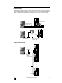
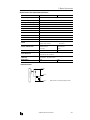
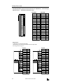
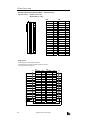
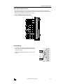
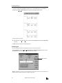
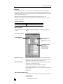
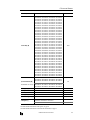
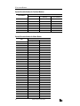
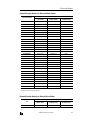
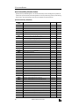
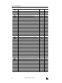
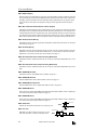
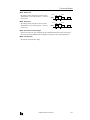
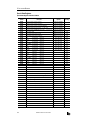
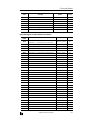
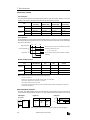
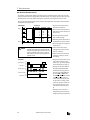
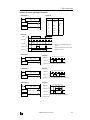
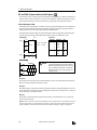
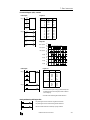
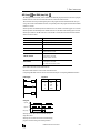
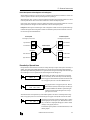
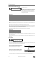
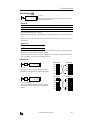
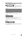
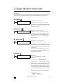
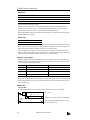
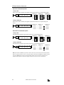
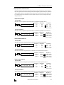
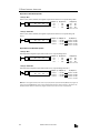
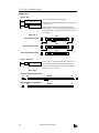
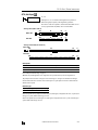
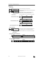
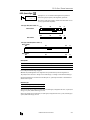
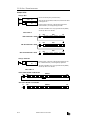
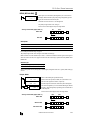
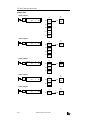
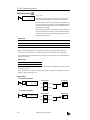
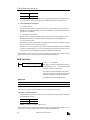
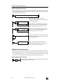
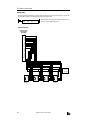
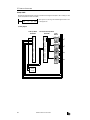
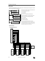
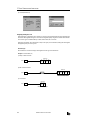
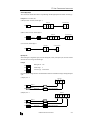
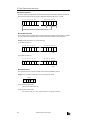
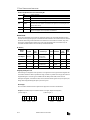
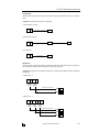
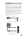
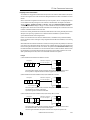
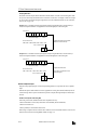
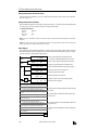
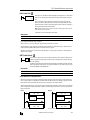
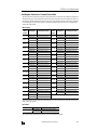
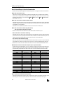
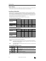
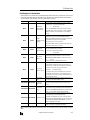
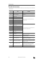
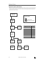
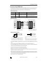
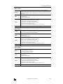
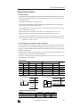
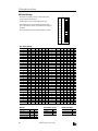
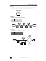
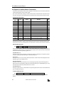
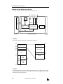
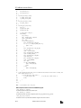
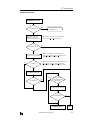
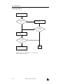
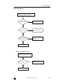
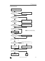
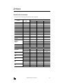
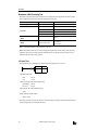
5: SPECIAL FUNCTIONS
Key Matrix Circuit
The key matrix structure includes sequentially-numbered input points along the top and sequentially-numbered output
points along the side. The I/O connecting blocks include a diode and a switch, as shown below.
DC Input Module
Input
I0
SW00
I1
SW01
I2
SW02
I3
SW03
I4
SW04
I5
In
SW05
Output
Output
Q0
Q1
Q2
Transistor
Sink Output
Module
Q3
Q0
SW10
SW11
SW12
SW13
SW14
SW15
SW20
SW21
SW22
SW23
SW24
SW25
SW30
SW31
SW32
SW33
SW34
SW35
SW40
SW41
SW42
SW43
SW44
SW45
Q1
Q2
Q3
Q4
Q4
Q5
Note: For the circuit above, a transistor sink output module must be used. When
using a transistor protect source output module, reverse the direction of diodes.
Diode rating is:
Qn
Average rectified current ≥ 100 mA
Reverse voltage ≥ 100V DC
Use switches with superior contact reliability.
Internal Relay Allocation
The example of a key matrix configuration shown on page 5-16 stores input information to 30 internal relays starting with
internal relay M100. The switches are assigned to internal relays as shown below:
Outputs
Inputs
I0
I1
I2
I3
I4
I5
Q0
M100
(SW00)
M101
(SW01)
M102
(SW02)
M103
(SW03)
M104
(SW04)
M105
(SW05)
Q1
M106
(SW10)
M107
(SW11)
M110
(SW12)
M111
(SW13)
M112
(SW14)
M113
(SW15)
Q2
M114
(SW20)
M115
(SW21)
M116
(SW22)
M117
(SW23)
M120
(SW24)
M121
(SW25)
Q3
M122
(SW30)
M123
(SW31)
M124
(SW32)
M125
(SW33)
M126
(SW34)
M127
(SW35)
Q4
M130
(SW40)
M131
(SW41)
M132
(SW42)
M133
(SW43)
M134
(SW44)
M135
(SW45)
OPENNET CONTROLLER USER’S MANUAL
5-17