1
eCOG1X User Manual
11
Version 2.7
Timer/Counter Module
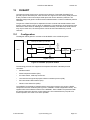
The TIM timer/counter module provides a set of timing and counting functions to the
eCOG1X device. Eight independent timers support a range of functions. The control and
configuration structure is made up of a register bank, asynchronous interfaces between the
controlling processor and each of the counters, and logic that generates interrupts and
events to wake up a sleeping processor.
Available timer functions include a 16 bit timer which may be used as a real-time clock; two
general purpose 16 bit timer/counters, two 16 bit timers with logic to provide a PWM output
function, a 16 bit watchdog timer; a 16 bit event capture timer, and a 24 bit long interval
timer.
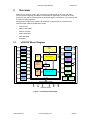
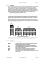
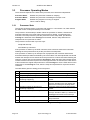
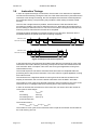
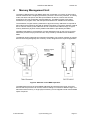
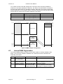
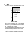
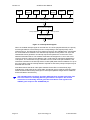
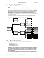
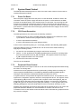
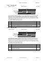
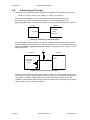
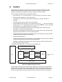
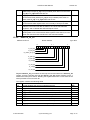
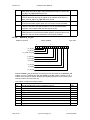
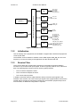
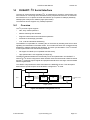
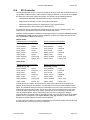
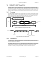
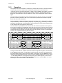
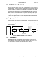
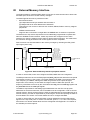
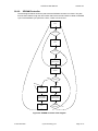
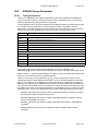
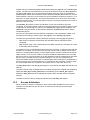
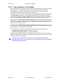
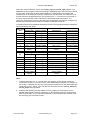
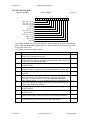
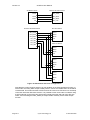
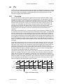
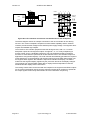
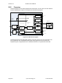
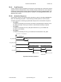
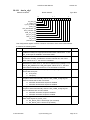
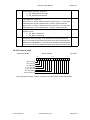
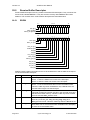
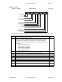
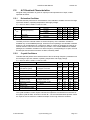
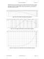
The diagram below shows the interfaces to the TIM module.
Interrupt and Wake Up Controller
CPU
Clocks
SSM
PWM1,2
Port
Configurator
TIM
Ports A to T
CNT1_TRIG
CNT2_TRIG
CAP_TRIG1-6
Register Interface
Figure 20: Timer peripheral module
)
11.1
Registers in the SSM module control and configure the separate clocks to the
timer functions. Registers in the Port Configurator configure chip I/O connections
to the timer functions.
Initialisation
Details of how to configure the frequencies of the clock sources for the timers are given in
section 7, System Support Module. Note that after a power on reset, all timers are disabled
and the values of the load/reload registers are cleared.
Each of the eight available timers has its own clock and reset input, individually controlled
via the SSM module control interface. Refer to the descriptions of the clock enable, clock
disable, reset set and reset clear registers for more details. Other SSM registers include bit
fields to select the clock source, divider tap and prescaler division factor for each timer.
21 October 2009
Cyan Technology Ltd
Page 11-1