1
UIM240XX Miniature Integrated Stepper Motor
FUNCTIONAL DESCRIPTION
Supply Voltage
UIM240xx controllers accept a wide range input voltage from 12 to 40VDC. (UIM24002 takes 10 – 35
VDC) In general, higher supply voltage improves motor performance under high speed situation, but
also increases the power loss and temperature raise.
Automatic Current Reduction (ACR)
UIM240XX controller is featured of Auto Current Reduction. If this function is enabled, when the motor
stops running, the phase current will be cut to 50% of the set value. As soon as the motor goes back to
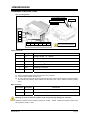
working, the current will go back to the set value. This function is enabled by turn the DIP1 (figure 0-4)
of the DIP switch 2 to the ON position.
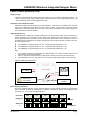
Adjust Output Current
UIM24002/04/08 is capable of providing maximum2A / 4A / 8A per phase output current respectively. In
specific application, the peak output current needs to be adjusted to meet the rated motor current. A
trimmer (potentiometer) is provided to serve this purpose at the bottom of the controller, as shown in
the following figure. Measuring the mapped voltage (Va) when tuning the trimmer provides a easy way
to set the output current.
For UIM24002, a mapped voltage “Va” of 0 - 2V proportionally represents 0 ~ 2A.
For UIM24004, a mapped voltage “Va” of 0 - 4V proportionally represents 0 ~ 4A.
For UIM24008, a mapped voltage “Va” of 0 - 4V proportionally represents 0 ~ 8A.
Note:
1.
2.
3.
The controller needs to be powered before mapped voltage “Va” can be measured. (Motor is not
required to be connected at this time.)
DIP1 (on the bottom side DIP switch 2) needs to be turned off to shut down the ACR Function.
After adjustment, user can choose to turn on the DIP1 to enable the automatic current reduction.
Figure 0-4: Adjusting the Output Current
Bottom Side
12 ~ 40VDC
Voltmeter
Mapped Voltage Va
Before measuring Va:
1) Apply Power
2) Turn off DIP1
Current Adjustment
Trimmer
Micro Stepping Resolution
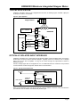
The micro stepping resolution is set by both DIP switch 1 and DIP switch 2 located at top and bottom
side of the driver as shown in following figure. UIM240xx controller can provide micro-stepping control
at full-step, 1/2, 1/4, 1/8 and 1/16 step resolutions.
Full
Resolution
1/2
1/8
1/4
1/16
DIP Switch
1
1 2
ON
1 2
ON
1 2
ON
1 2
ON
1 2
ON
DIP Switch
2
1 2
ON
1 2
ON
1 2
ON
1 2
ON
1 2
ON
MYOSTAT.CA
Actuator
For ACR use
Page 7