1
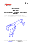
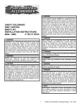
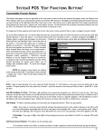
MAINTENANCE- AND
ASSEMBLY INSTRUCTIONS
MTV SERIES
Hypex d.o.o.
Alpska cesta 43, 4248 Lesce
Slovenija
Tel: +386 (0)4 531 8700 Fax: +386 (0)4 531 8740
www.unimotion.eu e-mail: [email protected]
www.unimotion.eu
MTV Series
MANUAL
NOTES
The specifications in order to improve the products in this catalogue are subject to change without notice.
MTV Series
MANUAL
TABLE OF CONTENTS
CONTENTS
PAGE
GENERAL INFORMATION
Used symbols
Tightening torques
General safety instructions
Safe operation
Modification of the linear unit
Labels and notices
Warranty
Handling the linear unit
Product description
Overview
_
_
_
_
_
_
_
_
_
_
_
_
_
_
_
_
_
_
_
_
_
_
_
_
_
_
_
_
_
_
_
_
_
_
_
_
_
_
_
_
_
_
_
_
_
_
_
_
_
_
_
_
_
_
_
1.005.0
1.005.0
1.005.0
1.005.0
1.005.0
1.010.0
1.010.0
1.010.0
1.015.0
1.025.0
1.030.0
_
_
_
_
_
_
_
_
_
_
_
_
_
_
_
_
_
_
_
_
_
_
_
_
_
_
_
_
1.030.0
1.030.0
1.030.0
1.035.0
1.040.0
1.045.0
1.050.0
MAINTENANCE
_
Lubrication of the ball nut and the carriage
Lubrication of the cover strip
_
Lubricant
_
Lubricant quantities and intervals
_
Normal operating conditions
_
_
_
_
_
_
_
_
_
_
_
_
_
_
_
_
_
_
_
1.065.0
1.065.0
1.065.0
1.065.0
1.065.0
1.065.0
ASSEMBLIES
MTV 65
MTV 80
_
_
_
_
_
_
_
_
_
1.070.0
1.070.0
1.075.0
_
_
_
_
_
_
_
_
_
_
_
_
_
_
_
_
_
_
_
_
_
_
_
_
1.080.0
1.080.0
1.080.0
1.085.0
1.085.0
1.090.0
1.090.0
1.095.0
MOUNTING
Fixing system - clamping fictures
Fixing system - tappered / pin holes
Magnetic field sensor
Mechanical and inductive switch
Motor with coupling
Motor with motor side drive
_
_
_
_
_
_
_
_
_
REPLACEMENT OF ASSEMBLIES
_
Removing the cover plate
_
Removing the protection strip _
Replacing the floating bearing _
Removing thespindle and spindle nut
Replacing the fixed bearing
_
Replacing spindle, ball nut or carriage
Replacing teh rail
_
_
The specifications in order to improve the products in this catalogue are subject to change without notice.
1.000.0
MTV Series
MANUAL
GENERAL INFORMATION
USED SYMBOLS
Linear Units
Remark, note
Linear Units
Linear Units
Linear Units
Linear Units
Warning!
For more information see the catalogue
Do not use glue in current step
Danger!
Risk of coming into contact with power
conducting parts! Cut off power supply!
Use dedicated tools for the current step
Caution!
MA
Keep Linear Unit clean!
Cover it, if necessary!
Use different tightening torque than in
the table on page 1.005.0
TIGHTENING TORQUES
Following tightening torques are recommended for screws of strength class 8.8
8.8
M2
M2,5
M3
M4
M5
M6
M8
M10
M12
Mmax
[ Nm ]
0.4
0.7
1.3
2.8
5.6
9.6
23
45
74
Screw
Tightening torque
GENERAL SAFETY INSTURCTIONS
To ensure the right functionality of the MTV Linear Unit, it must be handled with care. It is not allowed to put any
tools or any other items which can cause damage to the linear unit on the linear unit.
The Linear Unit must be proteceted against any liquid that can cause damage to it.
The MTV Linear unit must be placed in a dry, clean environment. For information on the conditions in which the
linear module can operate please contact us.
If the Linear Unit isn’t in use, place it in a dry, clean envrionment and cover it to prevent any damage.
REGULATION
SAFE
OPERATION
OF USE
The linear unit must not be put into service until the final machinery into which it is installed has been
declared in confirmity with the provisions of the Machinery Directive, where appropriate.
Each operation of the Linear Unit that is not in compliance with its intended use can lead to the product being
damaged, accidents and at the same time stoppages in production. To ensure a safe operation please refer to this
Instruction Manual and the operating manual of other machinery where the Linear Unit is to be incorporated.
The linear unit satisfies the requirements of EC Machinery Directive 2006/42/EC according to the European or
national standards of Safety of machinery:
·
EN ISO12100-1
·
EN ISO 12100-2
Checking linear unit
In accordance with the EU Health and Safety Directive 89/655/EEC article 4a, the operating company must
subject the unit to thorough checking prior to putting it into operation, after carrying out repairs, and after
malfunctions have occurred.
Requirements for personnel
The linear units may only be installed, operated, maintained, repaired or dismantled by appropriately qualified
personnel in accordance with specification User manual. All qualified personnel must have read and understood this
Instruction manual.
1.005.0
The specifications in order to improve the products in this catalogue are subject to change without notice.
MANUAL
MTV Series
MODIFICATION OF THE LINEAR UNIT
The linear unit must not be modified without our written consent. Any such unauthorised modification will void our
liability in respect of the unit. The operating company may only carry out the maintenance and repair work detailed
in this Instruction manual.
LABELS AND NOTICES
All notices and labels attached to the linear unit must be fully visible and must not be removed. They must ensure
compliance with all the instructions contained on them. Damaged or illegible notices and labels must be replaced.
WARRANTY
The warranty conditions are laid down in the terms and conditions of delivery and payment issued at the time of
order. Warranty cover will be annulled if:
·the unit is not operated in accordance with the stipulated regulation use;
·the instructions set out in this operating manual are not followed;
·the unit is modified without the consent of the manufacturers;
·the screws sealed by locking varnish are unlocked.
The manufacturer’s warranty in respect of maintenance and repair work applies only if original replacement parts
are used.
The specifications in order to improve the products in this catalogue are subject to change without notice.
1.010.0
MTV Series
MANUAL
HANDLING THE LINEAR UNIT
The Linear units are carefully packed in a HARD WOODEN BOX for a safe transportation.
To take the Linear Unit out of the box, please consider the following handling instructions:
- Never lift the Linear Unit by the END BLOCKS - see PICTURE A
- Never grab by the PROTECTION STRIP of the Linear Unit
- Never grab by the CARRIAGE
To take the Linear Unit out of the box, a suitable lifting tool is needed. Always lift and carry the Linear Unit by the
main profile.
The Linear Unit must be supported all the time during the handling until it is fixed - mounted on the place, where it is
meant to be. For correct handling please refer to page number 1.020.0
PICTURE A is showing, that handling with the Linear Unit in this position is wrong, because the profile, guides and
other components might get deflected or damaged.
Carrying the Linear Unit holding
the END BLOCKS isn’t allowed,
it must be carried holding the
PROFILE of the Linear Unit.
PICTURE A
1.015.0
The specifications in order to improve the products in this catalogue are subject to change without notice.
MTV Series
MANUAL
PICTURE B is showing correct handling of the Linear Unit.
PICTURE B
L > 2000mm
2/9L
1/9L
3/9L
2/9L
1/9L
L
PICTURE C is showing correct handling of the Linear Unit.
PICTURE C
L < 2000mm
2/7L
3/7L
2/7L
L
WARNING
Calculate the weight of the linear unit in order to choose the suitable lifting tool for the transportation of the Linear
Unit.
Please refer to the catalogue UNIMOTION - LINEAR UNITS for weight calculations.
Linear Unit needs to be stored in dry place and protected against corrosion. Make sure that there is no danger for
the Linear Unit to get damaged.
The specifications in order to improve the products in this catalogue are subject to change without notice.
1.020.0
MTV Series
MANUAL
PRODUCT DESCRIPTION
4
3
2
1
8
7
6
5
1 - Drive block with floating bearing
2 - Corrosion-resistant protection strip
3 - Ball screw tolerance ISO7 (ISO5 available on request)
4 - Carriage; with built in Magnets
5 - Aluminium profile-Hard anodized
6 - Integrated Linear Ball Guideway
7 - Central lubrication port; both sides
8 - End block with fixed bearing
1.025.0
The specifications in order to improve the products in this catalogue are subject to change without notice.
MTV Series
MANUAL
OVERVIEW
Identification label and additional or replacement parts of the Linear Unit
1 - ID number
2 - Serial number
3 - Type of Linear Unit (ordering code)
In the case of ordering additional or
replacement parts for the Linear Unit
there must be given all data from the
identification label.
www.unimotion.eu
The label must be fully visible (in particular details of the serial number) and must ensure compliance with
all the instructions contained on it. Damaged or illegible labels must be replaced.
MOUNTING
Fixing system
Linear Units
Linear Units
Linear Units
Linear Units
Linear Units
The Linear Unit must be mounted by
the aluminium profile with evenly
distributed clamping fixtures along
the entire length!
±0,1
Number of clamping fixtures
Please refer to our catalogue UNIMOTION
Linear Units on page 7.000.0
The modules are mounted by
using fixtures which are placed
in the slot on the side of the
profile.
MTV
A
B
[ mm ] [ mm ]
65
78
93
80
93
108
Fixing system - TAP/PIN Holes
Fixing the Linear Unit can also be done by the botom of profile using TAP / PIN holes, which can be made on request.
TAP / PIN holes can only be made based on the manufacturer’s drawing of the position and depth of
the TAP / PIN holes. For the drawings showing position and depth of TAP/PIN holes, please contact us.
The specifications in order to improve the products in this catalogue are subject to change without notice.
1.030.0
MTV Series
MANUAL
MOUNTING
Magnetic field sensor - REED SWITCH
Magnetic field sensor
STEP 1: The magnetic field sensor
must be placed in the slot of the
profile, that is made for this purpose.
Linear Units
Linear Units
Linear Units
Linear Units
Linear Units
For INFO about Profile slots
see UNIMOTION Catalogue.
Placing of the sensor can
done on the left or right side
of the profile of the Linear
Unit.
STEP 1
STEP 2: After the magnetic field
sensor is inserted and positioned in
the right location in the slot, tighten
the screw of the sensor.
STEP 2
Tighten the screw of the
magnetic field sensor REED switch with a
torque of MAX 0.6Nm
1.035.0
The specifications in order to improve the products in this catalogue are subject to change without notice.
MTV Series
MANUAL
MOUNTING
Mechanical and inductive switch
Activation block
STEP 1: Mount the activation block
on the side of the carriage by the
thread holes. The activation block
can be mounted on the carriage on
the left or right side. After the
activation block is placed, tighten
the screws.
STEP 1
STEP 2: Place either the mechanical
switch or the inductive switch with
brackets in the slots and position
them in the desired location. The
mechanical or inductive switch with
brackets can be placed in the slots
either on the left or right side of the
profile of the Linear Unit.
Mechanical switch with the bracket
Inductive switch with the bracket
STEP 2
STEP 3: After the mechanical or
inductive switch with bracket is
placed in the desired place in slots,
tighten the screws of the bracket.
STEP 3
For tightening torques for the screws please refer to page number 1.005.0
The specifications in order to improve the products in this catalogue are subject to change without notice.
1.040.0
MTV Series
MANUAL
MOUNTING
Motor with coupling
STEP 1: Attach the motor adapter on a preprepared location on the Linear Unit and screw
down.
STEP 1
STEP 2: Place the coupling halves on the drive
journal of the Linear Unit and the motor.
STEP 2
STEP 3: Ensure that the coupling halves and
the drive journals are correctly aligned.
Tighten the screws on the coupling
halves with the coupling tightening
torque.
Linear Units
Linear Units
Linear Units
Linear Units
Linear Units
STEP 4: Insert the coupling spider into one of
the coupling halves.
STEP 3
STEP 5: Attach the motor to the motor adapter
with screws and join the coupling halves
together at the same time.
STEP 4
STEP 3
STEP 5
The maximum torque and maximum
speed of the motor must never
exceed the limits of the Linear Unit!
Linear Units
Linear Units
Linear Units
Linear Units
Linear Units
For tightening torques for the screws please refer to page number 1.005.0
1.045.0
The specifications in order to improve the products in this catalogue are subject to change without notice.
MTV Series
MANUAL
MOUNTING
Motor Side Drive - MSD
The maximum speed and the maximum torque of the motor must not exceed the limits of the Linear Unit CTV.
For the values of speed and torque, please see our catalogue UNIMOTION Linear Units.
STEP 1
STEP 1: The housing of the motor
side drive - MSD must be mounted
and screwed on the drive block of
the linear unit. The housing can be
mounted in any way - UP, DOWN,
RIGHT or LEFT.
The motor side drive - MSD
can only be used on the Liner
unit with the ball screw journal
without keyway - ball screw
journal type 0 - more info see
our cataloge „UNIMOTION
Linear Units“ on page 6.005.0
STEP 2
STEP 2: After the housing has
been mounted on the Linear Unit,
the belt sprocket with toothed belt
and self locking device must be
fitted on the ball screw journal of
the Linear Unit. Adjust the
clearance as shown in the picture.
CLEARANCE:
This dimension is on the
linear unit side.
6
Type 1
Type 2
Types of journal tensioning
units, which are used on the
motor side.
For tightening torques for the screws please refer to page number 1.005.0
The specifications in order to improve the products in this catalogue are subject to change without notice.
1.050.0
MTV Series
MANUAL
MOUNTING
Motor side drive - MSD
RATIO i:=1
STEP 3a
STEP 3a: Mount the motor onto the
housing and lightly tension the
tightening screws of the motor.
When the motor is mounted, mount
the belt sprocket with the tension unit
onto the motor journal.
Adjust the clearance as shown in the
picture. Tension the tension unit.
Tension the motor with the belt with
the pretensioning force F and tighten
the motor down on the housing. The
pretensioning force F depends of the
size of the Linear Unit and motor.
6
CLEARANCE:
This dimension is
on the motor side
F
RATIO i:=1,5 or 2
STEP 3b
STEP 3b: Mount the motor onto the
housing and tension lightly the
tightening screws of the motor.
When the motor is mounted, mount
the belt sprocke tension unit onto the
motor journal.
Adjust the clearance as shown on the
picture. Tension the tension unit.
Tension the motor with the belt with
the pretensioning force F and tighten
the motor down on the housing.
The pretensioning force F depends of
the size of the Linear Unit and motor.
6
CLEARANCE:
This dimension is
on motor side
F
For tightening torques for the screws please refer to page number 1.005.0
1.055.0
The specifications in order to improve the products in this catalogue are subject to change without notice.
MANUAL
MTV Series
MOUNTING
Motor Side Drive - MSD
STEP 4: Mount the protection cover
on the housing of the motor side
drive - MSD. Tighten the screws.
STEP 4
Before the initial start-up, check if
everything is OK:
-electrical wiring
-mounted elements
-tightened screws
-correct tensioning of the belt
STEP 5: To dismount the motor
side drive - MSD, take precautions,
such as turning of the power supply
and prevent the carriage from
dropping, if it is in vertical position.
To dismount the MSD properly, look
at the mounting procedure.
STEP 5
Take care when loosening the
mounting screws on the motor
when the toothed belt is
tensioned.
For tightening torques for the screws please refer to page number 1.005.0
The specifications in order to improve the products in this catalogue are subject to change without notice.
1.060.0
MTV Series
MANUAL
MAINTENANCE
For each Linear Unit the basic lubrication is done in the factory before shipment.
All bearings have been lubricated for life and do not require any additional lubrication under normal operating
conditions.
Lubrication of the ball nut and the carriage
Ball nut and carriage lubrication is done via
lubricating nipple DIN 3405 D at the center of the
carriage.
Lubrication of the cover strip
Apply a thin oil film to the cover strip.
To ensure that the oil is applied equally on the cover
strip move the carriage up and down the profile.
Please note that, if the linear unit is working in an
area with many dust particles, the lubrication must be
reapplied every once in a while.
Lubricant
Recommended grease for the lubrication
Lubcon TURMOGREASE Highspeed L 252/3 (K HC P 2/3 K-50)
Recommended oil for steel cover strip
Lubcon TURMOFLUID ED 13
For lubrication and re-lubrication of linear units grease lubricant must only be used!
Do not use the grease which contains any solid parts!
Lubricant quantities and intervals
Ball Nut
type
MTV 65
MTV 80
Ball screw
Travel path
[d×I]
[ km ]
16 × 5
250
1.4
2.6
16 × 10
500
1.6
2.6
16 × 16
800
1.8
2.6
RSY
RSY
Grease - relubrication quantiy
Ball nut
Carriage
[ cm ] 3
[ cm3 ]
20 × 5
250
2
3
20 × 10
500
2.5
3.5
20 × 20
1000
3
4
The stated lubrication intervals in the table
are sufficient for normal operating conditions.
If you have special operating systems please
contact us.
The lubrication intervals are every 500
operating hours or after the specified travel
path stated in the table is reached. It
dependson which value is reached first.
Normal operating conditions
Temperature: 10 °C - 30 °C
Travel speed: = 1 m/s
Ball screw speed (RPM): 2500 1/min
Stroke:
MTV 65 > 60 mm
MTV 80 > 60 mm
Load: = 0.2 C
1.065.0
The specifications in order to improve the products in this catalogue are subject to change without notice.
MTV Series
MANUAL
ASSEMBLY MTV 65
1
11
12
7
8
4
3
9
6
5
2
13
ITEM
QTY
1
1
FRONT BLOCK MTV 65
47034
2
1
BACK BLOCK MTV 65
47033
3
1
CARRIAGE MTV 65
47035
4
1
PROFILE MTV 65
STROKE + 230
46032
5
1
RAIL GUIDE AR - HR 15 N
STROKE + 220
41518
6
2
CARRIAGE BLOCK AR15MN S V1 N
7
1
BALL SCREW MTV 65
8
1
PART NAME
10
LENGTH / QTY
45195
STROKE + 307
16 X 5
ISO7 (ISO5 ON REQUEST)
35452
16 X 10
ISO7 (ISO5 ON REQUEST)
35462
16 X 16
ISO7 (ISO5 ON REQUEST)
35463
BALL NUT RSY
16 X 5
45961
16 X 10
39440
39441
16 X 16
9
1
STAINLESS STEEL PROTECTION STRIP MTJ / MRJ 65
ALLEN SCREW M4 x 14 DIN 912
10
ID
STROKE + 248
41317
(RAIL LENGHT / 60) + 0,2
40690
Linear Units
11
1
KEY ROUNDED 4 x 4 x 20 DIN 6885A
12
2
MAGNET STRIP MTJ / MRJ 65
13
COVER FOR AR - HR 15
The specifications in order to improve the products in this catalogue are subject to change without notice.
Linear Units
Linear Units
Linear Units
Linear Units
40778
STROKE + 230
36933
(RAIL LENGTH / 60) + 0,2
-
1.070.0
MTV Series
MANUAL
ASSEMBLY MTV 80
1
12
13
7
8
4
3
9
6
5
11
2
14
ITEM
QTY
1
1
FRONT BLOCK MTV 80
53170
2
1
BACK BLOCK MTV 80
53166
3
1
CARRIAGE MTV 80
53210
4
1
PROFILE MTV 80
STROKE + 340
53234
5
1
RAIL GUIDE AR / HR 20 N
STROKE + 338
41515
6
2
CARRIAGE BLOCK AR20MN S V1 N
7
1
BALL SCREW MTV 80
8
1
PART NAME
10
LENGTH / QTY
45196
STROKE + 440
20 X 5
ISO7 (ISO5 ON REQUEST)
35453
20 X 10
ISO7 (ISO5 ON REQUEST)
42091
20 X 20
ISO7 (ISO5 ON REQUEST)
35464
BALL NUT RSY
20 X 5
39449
20 X 10
39442
39443
20 X 20
9
1
ID
STAINLESS STEEL PROTECTION STRIP MTJ / MRJ 80
STROKE + 362
41319
10
ALLEN SCREW M5 x 20 DIN 912
(RAIL LENGHT / 60)
52936
11
NUT M5 DIN557
(RAIL LENGHT / 60)
40769
Linear Units
12
1
KEY ROUNDED 5 x 5 x 25 DIN 6885A
13
2
MAGNET STRIP MTJ / MRJ 65 AND 80
14
1.075.0
COVER FOR AR / HR 20
Linear Units
Linear Units
Linear Units
Linear Units
37038
STROKE + 340
36933
(RAIL LENGTH / 60 )
-
The specifications in order to improve the products in this catalogue are subject to change without notice.
MTV Series
MANUAL
REPLACEMENT
Removing
OFspindle
ASSEMBLIES
and nut- MTV
from SERIES
module
Before any operation make sure that the module is disconnected from the power grid
to prevent possible injuries caused by the electrical current or moving parts.
Removing the cover plate
STEP 1: remove the screws.
STEP 2: remove the cover plate.
Note: for installing the cover plate reverse the
order of steps.
Replacing the protection strip
STEP 1: remove the cover plate.
STEP 2: loosen set screws holding the protection
strip.
STEP 3: remove protection strip and replace it with
new one.
STEP 2
STEP 4: attach the protection strip to one end of the
profile and screw cover plate on the carriage.
STEP 3
STEP 5: slide the carriage as close to the fixed end
of the protection strip as possible. Slide with a hand
over the protection strip towards the loosened end
to tighten it. At the end block hold the protection
strip tensioned and tighten two set screws to fix the
strip.
STEP 5
Note: all the screws (except set screws) must be glued (Loctite 243) and screwed
with the torque specified in the table on page 1.005.0 unless written otherwise at
the individual steps.
The specifications in order to improve the products in this catalogue are subject to change without notice.
1.080.0
MTV Series
MANUAL
Replacing the floating bearing
STEP 1: remove the cover plate and shaft key if
necessary.
STEP 2
STEP 2: remove four screws attaching the frontal
end block to the profile and the set screw securing
the bearing.
Remove frontal end block.
STEP 3
STEP 3: remove the circlip and bearing from the
shaft. Do not pull the bearing by outer ring!
STEP 4: put new bearing on the spindle and secure
it with circlip. Do not push the bearing by the outer
ring.
STEP 5: slide the frontal end block back in the
place and secure it with screws. Secure the bearing
with the set screw. Have the carriage as close as
possible to the frontal end block during this step.
STEP 6: attach the protection strip and cover plate
to the module as it is described in previous
chapters.
Removing the spindle and spindle nut
STEP 1: remove the frontal end block and the
floating bearing as described in the previous
chapters.
STEP 2
STEP 2: move the carriage as close to the end of
the spindle as possible. Remove key holding screw
and nut key. Remove the carriage nut and the ball
nut.
Note: when removing the ball nut put it on the tube
that has outer diameter the same as is inner
diameter of the spindle so that the balls will not fall
out.
STEP 3
STEP 2 MTV80: remove the screws in the rear end
block and slide the carriage to that end to unscrew
the cariage nut.
STEP 3: loosen the locking set screw on the side of
the rear end block and remove the bearing cover.
STEP 4
STEP 3 MTV80: remove the spindle, ball nut and
the rear end block. Loosen locking set screw in the
side of the rear end block. Remove the ball nut from
the spindle.
STEP 4: slide the spindle with fixed bearing out of
the rear end block.
Note: all the screws (except set screws) must be glued (Loctite 243) and screwed
with the torque specified in the table on page 1.005.0 unless written otherwise at
the individual steps.
1.085.0
The specifications in order to improve the products in this catalogue are subject to change without notice.
MTV Series
MANUAL
Replacing fixed bearing
STEP 1: slide the carriage as close as possible to
the frontal end block and remove two set screws in
the bottom of the frontal end block, save the rubber
cylinders and reuse them in step 6.
STEP 1
STEP 2
STEP 2: remove set screw and the bearing cover
from the rear end block and save the brass cylinder
(reuse it in step 6).
STEP 3: slide the carriage towards the rear end
block together with the spindle, so that the fixed
bearing comes out of the rear end block.
STEP 4: remove fixed bearing. Save the spacing
ring that lies between two bearings.
MA STEP 5: mount new fixed bearing. Insert the
spacing ring between two bearings and make sure
that the bearings are turned correctly.
STEP 6
STEP 6: assemble the module back together by:
- sliding the carriage towards frontal end block,
- inserting the fixed bearing cover (do not use glue),
- inserting the set screw that was removed from
frontal end block and one from rear end block.
Tighten set screw in the frontal end block to 1 Nm
and then loosen it for half a turn.
Replacing end blocks
Replacing the spindle, ball nut or the carriage
Note: the spindle and the ball nut must be replaced
at the same time as each nut is paired with specific
spindle.
STEP 1: remove the spindle and the ball nut from
the module as described in previous chapters.
STEP 2: slide the carriage from the module and
replace it with new one. Turn the carriage the same
way as was the old one. Take care that the balls do
not fall out of the rail-guide blocks (ignore this step if
you are not replacing carriage).
STEP 3
STEP 3: insert the spindle with the ball nut into the
module and secure the ball nut to the carriage with
key and screw (do not remove nut from the
spindle)(if spacers were installed before and after
the nut make sure they are installed as well).
Note: on MTV 80 spindle and nut are inserted from
other side than on MTV 65.
STEP 4: mount the fixed bearing to the spindle as
described in “Replacing fixed bearing”.
STEP 5: mount the leading profile and floating
bearing as described in “Replacing floating
bearing”.
STEP 6: finish by mounting the frontal end block.
Align it with the profile of the module before
tightening the screws. Secure the floating bearing
with set screw in the side of the frontal end block.
Note: all the screws (except set screws) must be glued (Loctite 243) and screwed
with the torque specified in the table on page 1.005.0 unless written otherwise at
the individual steps.
The specifications in order to improve the products in this catalogue are subject to change without notice.
1.090.0
MTV Series
MANUAL
Replacing the rail
STEP 1
Note: when replacing the rail consider that if the rail
is damaged it is possible that the carriage is also
damaged. We recommend that you change rail and
carriage together as this is the only way to ensure
smooth operation.
STEP 1: remove the cover plate and protection
strip. Unscrew screws in the rear end block and
loosen set screw in the frontal end block. Slide the
carriage with the spindle and ball nut from the
module.
STEP 2a
STEP 2a - MTV 65: remove plastic plugs and
screws from the rail and remove rail from the
module.
STEP 2b - MTV 80: remove plastic plugs, loosen
the screws and slide the rail with screws out of the
profile.
STEP 3: replace the rail with new one and insert it
into the profile. Center the rail in the profile with
caliper and tighten the screws. Do not glue the
screws on MTV 80.
STEP 2b
STEP 4: finish by installing the carriage, spindle,
frontal end block... As described in previous
chapters.
Note: all the screws (except set screws) must be glued (Loctite 243) and screwed
with the torque specified in the table on page 1.005.0 unless written otherwise at
the individual steps.
1.095.0
The specifications in order to improve the products in this catalogue are subject to change without notice.