1
PROFIBUS USER MANUAL
Leine & Linde AB
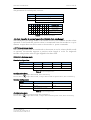
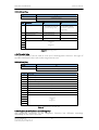
Table 31 Diagnostics, encoder serial number.................................................................... 28
Table 32 Standard Telegram 81........................................................................................... 31
Table 33 Telegram 81, signals ............................................................................................. 31
Table 34 PROFIdrive parameters supported ...................................................................... 32
Table 35 Encoder specific parameters supported ............................................................. 32
Table 36 Operating parameters supported ........................................................................ 33
Table 37 I&M functions supported ..................................................................................... 33
Table 38 Encoder parameters, DPV2................................................................................... 34
Table 39 Isochronous mode parameters ............................................................................ 35
Table 40 Diagnostics messages, DPV2 ................................................................................ 35
Table 41 Error messages, DPV2 ........................................................................................... 36
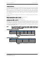
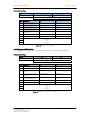
List of figures
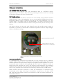
Figure 1 PCB-view of a cable gland PROFIBUS encoder ..........................................................7
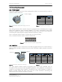
Figure 2 Orientation of M12 power supply connector ........................................................8
Figure 3 Terminal connection of power supply cables...........................................................8
Figure 4 Orientation of M12 bus connectors
......................................................................8
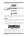
Figure 5 Terminal connection of bus line cables ....................................................................9
Figure 6 Cable assembling principal .........................................................................................9
Figure 7 Overview encoder profiles and related documents for PROFIBUS.......................11
Figure 8 Basic encoder functionality.......................................................................................13
Figure 9 Cyclic scaling ..............................................................................................................17
Figure 10 Non-cyclic scaling ....................................................................................................17
Figure 11 Commissioning example, DPV0..............................................................................29
Figure 12 Parameter assign, DPV0...........................................................................................30
Figure 13 Basic principal of the DP-cycle in isochronous mode..........................................32
Figure 14 Assigning parameters, DPV2 Class 4......................................................................37
Figure 15 Isochrone mode parameter settings, DP-slave .....................................................38
Figure 16 IDP master settings, BUS .........................................................................................38
Figure 17 Network settings, BUS .............................................................................................39
Figure 18 Isochrone mode parameter settings, BUS .............................................................39
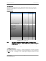
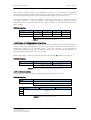
Leine & Linde AB claims copyright on this documentation. It is not allowed to modify,
extend or to hand over to a third party and/or copy this documentation without
written approval from Leine & Linde AB.
Specifications and content in this document are subject to change without prior
notice due to our continuous strives to improve functionality and performance of our
products.
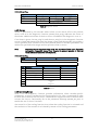
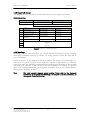
Part Id: 634814-01
Document Id: 634814 Ver. 01
Publication date: 2008-02-05
4