1
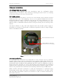
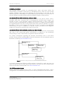
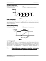
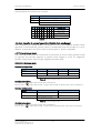
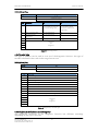
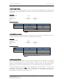
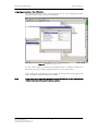
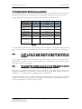
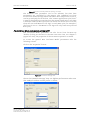
PROFIBUS USER MANUAL
Leine & Linde AB
2 Encoder Installation
2.1 Settings inside the encoder
The encoder node address and bus termination must be configured during
commissioning of the device. This is done by removing the back cover, i.e. screwing
off the three screws at the rear of the encoder.
2.1.1 Node address
The node address of the device can be set via two decimal rotary switches located
inside the back cover. The weighting, x10 or x1 are specified beside the switches.
Permissible address range is between 0 and 99 but the lower addresses 0 to 2 are
usually used by the master and not recommended to be used by the device. Each
address used in a PROFIBUS network must be unique and may not be used by other
devices.
The device address is only read and adopted when the encoder power supply is
switched on. A restart of the encoder is therefore required in order to adopt changes
done to the address settings.
Bus termination on/off
Node address switches
(x10 to the left, x1 to the right)
Figure 1 PCB-view of a cable gland PROFIBUS encoder
2.1.2 Bus termination
In a PROFIBUS net, all devices are connected in a bus structure. Up to 32 devices
(master and/or slaves) can be connected in one segment. When more devices are
needed repeaters should be used to amplify the signals between segments. An active
termination must be added in the beginning and end of each bus segment in order to
ensure error-free operation. In case of the encoder such terminators are integrated
inside the back cover and can be activated via dip switches as shown in figure 1. If the
device is un-powered the A and B lines are internally terminated by a 220Ω resistor.
When encoder with M12 connectors is used the termination is conducted using
terminating resistor plug. The plug is assembled in resemblance to the M12 cables
and both male and female contacts are available in order to enable termination in
both ends of the bus.
Part Id: 634814-01
Document Id: 634814 Ver. 01
Publication date: 2008-02-05
7