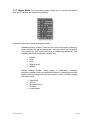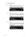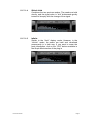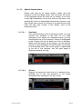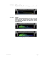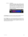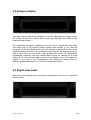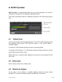
1
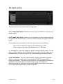
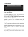
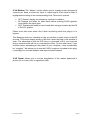
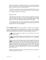
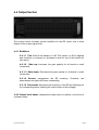
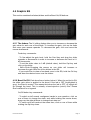
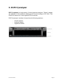
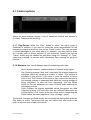
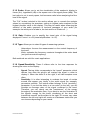
Users Manual INDEX 1. Quick start page 3 2. Initial approach to DUY31 page 4 3. Inserting DUY31 in Audio or Aux tracks page 5 3.1 ProTools TDM users page 5 3.2 Audio Units (AU), RTAS, MAS and VST users page 6 DUY31|graphic page 7 4.1 Edition bar page 8 4. 4.1.1 Patch Manager page 8 4.1.2 Edit Buttons page 10 4.1.3 Memory Buttons page 10 4.1.4 Help page 11 4.2 Input section page 12 4.2.1 Input level meter page 12 4.2.2 Input gain level page 12 4.2.3 Live button page 12 4.3 Control options page 13 4.3.1 Band/gain display page 13 4.3.2 dB Range page 13 4.3.3 Transparency page 13 4.3.4 Meters page 14 4.3.5 Scale page 14 4.3.6 Mode (G-Eq/Pinker) page 15 4.3.7 Feedback Scan page 16 4.4 Output section page 17 4.4.1 Modifiers page 17 4.4.2 Output level meter page 17 4.5 Graphic EQ 4.5.1 The faders page 18 4.5.2 Band On/Off page 18 4.6 Memory scenes DUY31 User Manual page 18 page 19 Page 1 5. DUY31|analyzer page 20 5.1 Control options page 21 5.1.1 Play/Pause page 21 5.1.2 Measure page 21 5.1.3 Scale page 22 5.1.4 Gain page 22 5.1.5 Type page 22 5.1.6 Speed/Sensitivity page 22 5.1.7 Graph Mode page 23 5.1.7.1 Standard display modes 5.1.7.1.1 5.1.7.1.2 5.1.7.1.3 5.1.7.1.4 5.1.7.1.5 Simple Slide Hold Slide & Hold Infinite 5.1.7.2 Special display modes 5.1.7.2.1 5.1.7.2.2 5.1.7.2.3 5.1.7.2.4 5.1.7.2.5 6. page 24 page 26 One Band 3D Line 3D Smooth Line 3D Bars Levellogram 5.1.8 Channel page 28 5.1.9 3D Lag page 28 5.2 Analyzer display page 29 5.3 Signal level meter page 29 DUY31|noiser page 30 6.1 Output level page 30 6.2 Noise type page 30 6.3 Waveform display page 30 6.4 Edit & Memory Buttons page 31 DUY31 User Manual Page 2 1. Quick start Please read DUY31’s Installation Guide to install the software. You will find it included both in the Downloaded version or in the CD you purchased, according to the version you chose when you purchased the software. If you have purchased DUY31 as an online download, make sure that the software has been downloaded correctly. Once you uncompressed the downloaded file, which is a disk image (.dmg), double-click on it. This will mount a volume/folder. Open it. One of the files it contains is the installer for DUY 31. It should look like this: If the icon looks different, it means that you may have had some problem during the download and the file may be corrupted. Therefore, please download the file again and repeat the process. To install the software, double-click on the Install icon. Read the License Agreement very carefully and click on the “Agree” button only if you agree to accept the terms and conditions of the provided license agreement. You will be asked to enter your serial number. Please enter it. Make sure the serial number is inserted in capital letters, with no spaces and looking similar to this: XXXXX-XXXXX-XXXXX-XXXXX, where “X” can be a capital letter or a number. The serial number will be provided at the top of your registration card, if you have purchased a boxed CD, or in the email we provided if you have purchased the software as an online download. You must also install DUY31’s settings, included in a separate installer, using the same procedure as detailed above. DUY31 User Manual Page 3 2. Initial approach to DUY31 DUY31 is a suite of 3 high quality plug-ins: • • • DUY31|graph: A 31-band EQ with amazing versatility and control over the full audio spectrum. DUY31|analyzer: An amazing tool that will aid you in controlling and planning your spectrum visually. DUY31|noiser: A white and pink noise generator to add extra EQ’ing features. The uses of these amazing plug-ins is endless. In the studio, DUY31|graph and DUY31|analyzer can serve a high degree of control over your recording. In live applications, you can combine these two plug-ins with DUY31|noiser to equalize your space/room (usually called “Room EQ’ing”). DUY31|graph DUY31|analyzer DUY31|noiser DUY31 User Manual Page 4 3. Inserting DUY31 in Audio or Aux tracks DUY31 is a suite of 3 plug-ins: DUY31|graphic, DUY31|analyzer and DUY31|noiser. They are available for TDM, RTAS, Audio Units (AU), MAS (MOTU Audio System) & VST for Mac. 3.1 ProTools TDM users In ProTools, these 3 plug-ins are presented under the following categories: - DUY31|graphic: EQ DUY31|analyzer & DUY31|noiser: Other 3.1.1 DUY31|graphic: This plug-in, in its TDM version, is presented as a Mono to Mono equalization effect. Depending on your version of ProTools or other DAE-aware application, the process of inserting the plug-in is done in one way or another. Look for the plug-in either in the list of Mono to Mono plug-ins or, if they’re arranged by categories/families, you will find it in the “EQ” section. If you’re going to be using DUY31|graphic as a Stereo or Multichannel process which requires precise correlation, you should insert your plug-in in “multi-mono” mode, making sure that the “Link” button is active. DUY31 User Manual Page 5 3.1.2 DUY31|analyzer & DUY31|noiser: These 2 plug-ins are included in the “Other” category within ProTools. They are available as a Mono or as a Stereo plug-in instance. 3.2 Audio Units (AU), RTAS, MAS and VST users You can insert any of the 3 plug-ins either as a Stereo or Mono instance, according to your needs. DUY31 User Manual Page 6 4. DUY31|graphic DUY31|graphic is a high-quality 31-band EQ. These 31 bands are spaced in 1/3rd octaves, starting at 20 Hz and ending at 20.5 KHz. This represents the historical 31-band graphic EQ. DUY31|graphic’s window is formed by the following sections: - The Edition Bar Input Section Control options Output Section Graphic EQ Memory scenes DUY31 User Manual Page 7 4.1 Edition Bar The Edition Bar allows to rapidly access the fast-edition functions and the edition, organization and search of settings/presets. DUY 31 graphic’s Edition Bar consists of the following parts: 4.1.1 “Patch Manager” Pop-Up Menu The Patch Manager arranges the presets/settings documents. During the installation process, the presets will be placed in a folder named “DUY 31 graphic patches” in the Preferences directory. Note that with all DUY products, we also name “presets” as “patches” or “settings”. This folder contains a series of subfolders that contain the presets themselves. The subfolders correspond to the categories of presets within the main (root) Settings folder. The first part of the menu (above a separation line) includes the managing options, such as saving presets. Below the separation line you’ll see the list of presets, grouped in families (see image above) The functions you can use are: DUY31 User Manual Page 8 a) Save as: saves the active setting . A window will appear, allowing you to change the name you would like to give the preset and where you would like to store it on your drive. b) Save in Patch Manager as: Does exactly the same as the standard “save as” function, but the setting is saved directly into the main folder where the current settings are stored. c) Load: allows you to select a settings document and open it to apply it to your audio. d) Preferences: Shows the options you have within the Patch Manager. - - - - DUY31 User Manual Cache On: allows you to activate the loading of all the presets in memory, so that the system doesn’t have to read from disk each time a setting is used. This is helpful to reduce the time of reading to disk. Cache Patches: When the “cache on” is active, if you select this option, all the presets will be loaded when you use DUY31|graphic for the first time. Cache Patches when needed: If you select this option, only the presets that are called or used during a session will be saved in the cache. Select Root Folder: allows you to choose the folder that contains the structure of subfolders that holds the presets. You can have an infinite presets folders in your hard disk, but only one can be active at a time. So, if you prefer to change the name of the folder or where it is stored in your hard drive, you can manually move it and then select the position where it’s located by using this option. Once you have done this, click on the “Re-build Patches List” when you click OK if you would like the list of presets to be refreshed. Page 9 4.1.2 Edit Buttons (Copy, Paste, Undo, Redo) These buttons allow you to copy, paste, undo or redo. If it’s not possible to use a certain function, the button will be tagged in lighter gray. This will occur, for example, if there is nothing to Paste (which would mean you haven’t clicked “Copy” first). “Copy” will copy the state of a whole screen. This information can then be pasted using the “Paste” button in this instance of DUY31|graphic or in another. The “Undo” and “Redo” buttons allow you to return to the “previous” or “next” state after your last edition. A history of the last 10 editions is stored. Therefore, you have 10 levels of Undo or Redo. If you would like to clean the history or stored states, click on the Copy button while holding the Opt key. In depth, the “Copy” function acquires data of the plug-in and audio scene: the noise contents and the plug-in’s parameters. 4.1.3 Memory Buttons (A, B, C, D, E, F) The A, B, C, D, E, F buttons are temporary memories which are useful in many cases. For example, if you would like to compare several settings. To save a screen state to one of these memories, simply click on the memory button (A, B, C, D, E or F). If the memory is empty, the button will be highlighted in gray. Once you click on the button and save the content of the screen, the lettering will turn black. If you want to empty a memory, click on the button while holding the Opt key. If you would like to load all the memories in a circular way, click on the Rotate button. If you only have memories A and B full, the sequence in rotation from one memory to another will be A, B, A, B... DUY31 User Manual Page 10 4.1.4 Help DUY31|graphic has Help Balloons and also Spoken Help (you will need the Speech Manager in your system for Spoken Help to function). To use any of these two, click the respective icons. DUY31 User Manual Page 11 4.2 Input section The Input section is formed by the following parts: 4.2.1 Input level meter: displays the input value in realtime, in the form of a plasma meter. 4.2.2 Input gain level: allows you to decrease the input signal using the provided slider. At the bottom, a numeric readout displays the signal decrease in dB. The available key commands for this input gain slider are the following: - Opt + click on the slider: jumps to the default value ( 0 dB) - Cmd + drag on the silder: fine-adjustment in 0.1 dB steps It’s important to check the system’s internal overflow process state. For this reason, DUY31|graphic has a clipping led at the input. If the led lights up, it’s advisable that you reduce the input level to avoid having unwanted distortion. 4.2.3 Live button: The Live button enables a phase optimisation algorithm which, in some rare cases, may compromise the 20-27 Hz range (which is hardly ever audible). This option is very useful for Live applications, but may be advisable to have this option unchecked when using the software for Mastering, since you may get a totally normal added noise (zipper noise) when you’re moving the graphic EQ controls in realtime. DUY31 User Manual Page 12 4.3 Control options Above the graphic EQ sliders, a set of advanced controls and options is provided. These are the following: 4.3.1 Band/gain display: Displays information related to the adjustment of the level of the band depending on the position of the mouse. If you click on one of the EQ’s sliders, and drag the slider towards the desired position, you will visualize the frequency value corresponding to the band and the Gain value at which you’re setting the slider. If you don’t click on any of the EQ’s sliders, the displayed frequency value will correspond to the position of the mouse. You will observe 2 gain values. The top value shows the current slider value. The bottom value shows the new gain amount at which the mouse is pointing. 4.3.2 dB Range: Allows you to set the maximum and minimum range above or below 0 dB (default value) for all the sliders. The possible range values are 6, 12, 18 and 24 dB. For example, if you set the range value to 12, the central value of the EQ’s sliders will be 0 dB, and will allow you to increase +12 dB by moving the slider upwards, or to decrease the band gain by -12 dB if the slider is moved downwards. 4.3.3 Transparency: This slider allows you to give a certain transparency to the sliders in the EQ. This is especially useful when you’re using the “Meters” option to visualize the frequency contents on each band, allowing for a clearer display of the frequency contents in realtime. DUY31 User Manual Page 13 4.3.4 Meters: The “Meters” section allows you to visually monitor frequencial contents per band of either the input or output signal. Each band’s slider is highlighted according to the corresponding level. There are 3 options: • • • OFF: Doesn’t display any frequency contents in realtime. IN: Displays the levels for each band before entering DUY31|graphic (even before the input gain). OUT: Displays the levels for each band after being processed by the EQ in DUY 31 graphic. Please note that some hosts don’t allow monitoring while the plug-in is in bypass. This Metering section is intended to help you perform a quick-check of the EQ process. This visual display works in idle time, when the plug-in the window is open. The advantage is that no DSP time is consumed, and if you close the plug-in window there will be no consumption either. On the other hand, if you use this option, depending on the power of your computer, it may occasionally be “sluggish”. We advise you to use the DUY31|analyzer (included in this plugin package) for accurate analysis and improved performance. 4.3.5 Scale: Allows you to set the visualization of the meters explained in point 4.3.4 to Linear (Lin) or logarithmic (dB). DUY31 User Manual Page 14 4.3.6 Mode: This option is extremely interesting for live applications or any room frequency compensation/calibration use. You have 2 choices within this menu: 4.3.6.1 G-Eq: When this option is selected, the plug-in functions as a standard 31-band graphic equalizer. 4.3.6.2 “Pinker”: This option will allow you to compensate the frequency character of the audio system used in the sonic room (or open space) environment where your audio is being performed. In order to start the room calibration process, which will evaluate the room’s acoustics and the frequency response of the monitors, you will need: - An omnidirectional microphone with the flattest frequency response possible (a calibration microphone) - A pink noise generator. Pink noise has equal energy in all octaves. A noise generator is provided in this DUY 31 suite of plug-ins, (DUY31|noiser). Procedure: a) Insert DUY31|noiser in a track. Select the Pink Noise option from its interface. You will hear noise, which should be output using your PA system in live applications or your monitoring system for reduced studio or similar environments. You should output using a realistic performance level (therefore, don’t try to output a lower level than the one you’ll be using during the “real” performance). Please be careful with high signal levels. They can damage your hearing! b) Create a track (direct input or auxiliary track) which collects the signal received from the calibration microphone. This is the track where DUY31|graphic will be inserted. c) Make sure that the input signal is around -12 dB to allow for occasional peaks in the signal. You shouldn’t allow any clipping or distortion at the input during the process. It’s important that you make sure that you mute the track’s output (obviously not the input) in order to avoid feedback!!! d) While receiving the microphone’s signal, click on the “Pinker” button. A small bar below the button will indicate the stage of the room callibration. DUY31 User Manual Page 15 e) Once the calibration or “pinking” process is over, you will see that the sliders on each one of the EQ’s bands have automatically adapted the gain for each band to the room’s characteristics. f) Obviously, you should now save the obtained calibration state in order to recall it at a later time. You can do this by saving as a preset using the Patch Manager located in the Edition bar. Additional issues: - Note that above the “Pinker” button on the user interface, you have a “CLR” button. By clicking it, you can clear the calibration data received until that moment. This doesn’t change the slider gain values. It simply allows you to start the callibration process with fresh data again. - It may seem obvious, but you shouldn’t allow for any other signal than the noise itself to enter your system during the calibration process. This would result in an incorrect calibration. 4.3.7 Feedback Scan: This option includes a series of very frequencyprecise notch filters that will avoid feedback in your system. This is especially useful for live applications, but may also come in handy if you want to reject a certain frequency within the EQ system. You have 3 options in this menu: 1) OFF: Doesn’t process the audio with any notch filter (it’s a sort of bypass of this section). 2) AUTO: Automatically detects typical frequencies in the microphone feedback range, which outstand from the audio level in a considerable way. 3) ON: Lets you select the frequency values to be rejected with the notch filters. You have a total of 6 notch filters available. When you insert the plug-in for the first time, you will see 6 “Free” tags in this section. To activate one notch filter, click on any of those free available slots while holding the Cmd key. The default frequency is set to 1 KHz. To modify this value, hold the Cmd button again and move your mouse upwards or downwards to adjust the frequency value. To clear a slot, hold the Opt key and click on it. Please note that when the AUTO or ON options are active, the sliders on the EQ may move a little slower. DUY31 User Manual Page 16 4.4 Output Section The output section includes several modifiers for the EQ levels, and a visual display of the output signal level. 4.4.1 Modifiers: 4.4.1.1 Flat: Sets all the bands to 0 dB. This means, no EQ is applied and therefore no increase or decrease in level for any of the bands will take place. 4.4.1.2 Gain up: Increases the gain equally for all bands in small increments. 4.4.1.3 Gain down: Decreases the gain equally for all bands in small increments. 4.4.1.4 Accent: exaggerates the EQ tendency. Therefore, the attenuations and gains are more outstanding. 4.4.1.5 De-accent: decreases the tendency of the EQ by flattening out the outstanding values (making the result closer to the average).. 4.4.2 Output level meter: displays the output value in realtime, in the form of a plasma meter. DUY31 User Manual Page 17 4.5 Graphic EQ This section contains the faders/sliders and the Band On/Off buttons. 4.5.1 The faders: The 31 sliding faders allow you to increase or decrease the gain value for each one of the bands. To increase the gain, click on the fader and move your mouse upwards. To decrease the gain, click and move the mouse downwards. Fader key commands: - To fine-adjust the gain level, hold the Cmd key and drag the slider upwards or downwards in order to increase or decrease the level in 0.1 dB increments. - To set the slider value to 0 dB (default value), hold the Opt key and click on the slider. - Shift+Click+Dragging the mouse on one slider will increase or decrease the gain value for all the sliders in the EQ. - If you would like to draw a free-hand curve in the EQ, hold the Ctrl key and draw the desired curve over the sliders. 4.5.2 Band On/Off: Each band has a button below it. When the red led is ON, the slider gain value is applied to the band. If the led is OFF (highlighted in grey), the band is muted. This means that when the led is OFF, no signal will go through the band. This is actually a band-rejection (notch) filter. Please don’t mistake it for a bypass! On/Off button key commands: - To switch on/off several contiguous bands in one operation, click on one of them to change the state, and while holding the mouse down, drag over the other buttons to change their state too. - To swith on/off all bands at the same time, click on one of them while holding the Opt key down. DUY31 User Manual Page 18 4.6 Memory scenes DUY31|graphic provides a Memory section in the lower part of the interface. You have a total of 40 memory scenes, split up in 2 banks (A & B), numbered 1 to 20. These 40 scenes are meant for complex projects that may require different settings throughout the evolution of the material. They are a simple group of memories which can be recalled at any time. To memorize a scene, click on the Store button, followed by the number you’d like to store it on (1 to 20, either on bank A or B). To recall a memory scene at any time, simply click on its number. To delete a memory, simply click on the Clear button, followed by the number you’d like to erase. These memory scenes are stored in your session. DUY31 User Manual Page 19 5. DUY31|analyzer DUY31|analyzer is a high-quality 31-band spectrum analyzer. These 31 bands are spaced in 1/3rd octaves, starting at 20 Hz and ending at 20.5 KHz. This follows the historical 31-band graphic EQ & analyzer. DUY31|analyzer’s window is formed by the following sections: - Control options Analyzer display Signal level meter DUY31 User Manual Page 20 5.1 Control options Above the main analyzer display, a set of advanced controls and options is provided. These are the following: 5.1.1 Play/Pause: While the “Play” button is active, the input signal is visualized in realtime. If you want to freeze the visual representation of the frequency contents at any time, click on the “Pause” button. This may be useful in certain passages of your track where, for example, you may need to focus on a certain peak or abrupt variation of your spectrum. Please note that the “Pause” button may be needed as well when using the “Average” or “Peak” measuring methods, to prevent audio information from entering the plug-in’s process. 5.1.2 Measure: You have 3 different ways of measuring audio data: - - Norm: Normal measure (realtime display of entered audio signal) Ave: Running average. Note that it calculates the average frequency amplitude values by sampling a number of ‘takes’. This number is visualized in this section. If you want to clear the number of takes, click on the “CLR” button in this section. Also, make sure that you’re not entering useless or unwanted data while the running average is being calculated. To stop this from happening, click the Pause button on the left whenever you need to avoid audio entering the calculation process. Peak: Displays the highest amplitude values throughout the data collection process. You may also clear the collected data peaks by clicking on the “CLR” button at the top of this section. Regarding the Pause button, the same applies as in the “Average” option. The Normal, Average and Peak modes are constantly monitoring data while the Play button is active. This means that you can switch from one mode to the other at any time and compare the values. DUY31 User Manual Page 21 5.1.3 Scale: Allows you to set the visualization of the analyzer’s display to Linear (Lin), logarithmic (dB) or the square root of the signal power (dBq). This last option is not in most papers, but becomes useful when analyzing the floor level of the signal. The “Full” button included in this section allows you to re-scale the analysis values by normalizing the spectrum, setting to highest value analyzed to the highest possible value in the display. This may be useful when observing the variation of the audio spectrum in low-level passages of your audio (for example: the initial part of a fade-in, the last section of a fade out…) 5.1.4 Gain: Enables you to amplify the visual gain of the signal being displayed. From x1 to x16 (visual amplification 1 to 16). 5.1.5 Type: Allows you to select 2 types of measuring systems: - Heterodyne: focuses the measurement on the central frequency of the band Wide: evaluates the frequency contents throughout the entire band (not just the central frequency) Both methods are valid for music applications. 5.1.6 Speed/Sensitivity: These 2 sliders refer to the time response for drawing the curve on the display. - - Speed: The top slider corresponds to the “speed” parameter, which defines how often the plug-in will analyze the signal in order to display it. When the slider is at the right, it will take samples more often. Sensitivity: It is often interesting to evaluate the levels of certain sounds that appear very briefly in the audio signal (for example, percussive sounds). The bottom slider belongs to the “sensitivity” parameter. If you set the slider to a low value (to the left), you will visualize an average value of the signal contained in the band. Therefore, you can clearly see the “persistance” of the energy throughout the evaluation time. If you want to see the fluctuation of the signal’s energy for the band, visualizing all the short and transitional sounds, set the slider to the right. Of course, any value between the left and right will create an in-between status that you can choose depending on your needs. DUY31 User Manual Page 22 5.1.7 Graph Mode: This pop-down menu allows you to choose the format how you’ll visualize the signal in the display. In general, there are 2 types of display modes: - Standard display modes: These are the most usual types of display, which display the signal graphically, and also show the numerical level values for each band according to measuring standards. The available standard visualization modes are: - Simple Slide Hold Slide & Hold Infinite Special display modes: These types of visualization combine frequency analysis with the additional feature of displaying how the signal evolves throughout the time domain, some of them unique and very useful! DUY31 User Manual One Band 3D Line 3D Round Line 3D Bars Levellogram Page 23 5.1.7.1 Standard display modes 5.1.7.1.1 Simple The “Simple” display mode shows the numeric level values for each band as seen in the following image: 5.1.7.1.2 Slide The “Slide” display mode functions in an equivalent way to the “Simple” mode, although the signal peaks are slowly lowered when the signal decreases within a band. 5.1.7.1.3 Hold This display mode holds for a short amount of time the peaks for each band, displaying them clearly and leaving space below the “peak hat” to visualize the signal continuously. DUY31 User Manual Page 24 5.1.7.1.4 Slide & Hold Combines the two previous modes. The peaks are held shortly, and the signal value is “slid” downwards gently instead of abruptly with the change of the signal. 5.1.7.1.5 Infinite Similar to the “Hold” display mode. However, in the “infinite” mode, the peaks are held and visualized permanently in a clear way. If you want to erase the peak information, click on the “CLR” button available in the Graph Mode section of the plug-in DUY31 User Manual Page 25 5.1.7.2 Special display modes Please note that for all these display modes (with the exception of the One-Band mode), you can select the colors of the displayed signal. We have set, by default, a red color for the high frequencies, and a blue color for the lower ones, grading the colors of intermediate frequencies. However, you may modify these colors by clicking on a small button at the lower left and right corners of the display, next to the frequency values. 5.1.7.2.1 One Band This unusual display mode is extremely useful. You can visualize the evolution of the level for one band throughout time. Below the displayed signal, you will observe that one of the frequency values is highlighted in red. Simply click on the band you’d like to visualize. When you enter signal into the plug-in, you will see the change in level throughout the time domain, exclusively for the selected band. The current signal is represented at the left of the interface, and the past signal is displaced towards the right. 5.1.7.2.2 3D Line Displays the spectrum in the form of a continuous line, allowing you to see the evolution of the signal throughout time (setting the “3D lag” value). DUY31 User Manual Page 26 5.1.7.2.3 3D Smooth Line Equivalent to the “3D Line” display mode, it visually rounds out the peaks. 5.1.7.2.4 3D Bars Displays the signal frequencially in the form of one-perband vertical bars. Also very useful to see the evolution of the spectrum throughout time, setting the “3D Lag” value accordingly. “3D Bars” with little or no “3D Lag” “3D Bars” with “3D Lag” to approximately 75% DUY31 User Manual Page 27 5.1.7.2.5 Levellogram Also an unusual display system, although extremely useful: the current signal is displayed at the bottom of the displayed, and rolled upwards as time goes by. The colors indicate higher or lower signal levels for each band. Here, the color set on the right hand side of the display corresponds to the higher levels, whereas the color set on the left side of the display is related to the lower levels of the signal. 5.1.8 Channel: Lets you select if you want to display the frequency analysis of the left (L), right (R) or the sum of the left and right channels (Sum). 5.1.9 3D Lag: In any of the 3D display modes, this slider allows you to control the length of time variation of the signal displayed. A higher value (to the right) will display the frequency contents of a longer amount of time. A low value will just show the instant signal, with no display of the variation of the signal throughout the time domain. DUY31 User Manual Page 28 5.2 Analyzer display The main central area of the interface is used for displaying the signal as per the values set with the controls above, and very especially, according to the selected Graph Mode. As a redundant comment (explained in point 5.1.6.2), please note that when you select any of the special display modes (see section 5.1.6), with the exception of the One-Band mode, you are allowed to select the colors of the displayed signal. We have set, by default, a red color for the high frequencies, and a blue color for the lower ones, grading the colors of intermediate frequencies. However, you may modify these colors by clicking on a small button at the lower left and right corners of the display, next to the frequency values. In the case of the “Levellogram”, the meaning of these colors is different (please read section 5.1.6.2.5 for further information). 5.3 Signal level meter Below the main display area, the signal is displayed in the form of a standard plasma meter. DUY31 User Manual Page 29 6. DUY31|noiser DUY31|noiser is a high-quality white and pink noise generator. No audio is entered into the plug-in. It is uniquely a signal generator. This utility is extremely useful for callibration purposes, and ridiculously easy to use! 6.1 Output level Lets you set the value of the generated noise. The level in dB is displayed, with the maximum value being “0 dB” and the lowest “-∞ dB“ (minus infinity = inaudible signal). To return to 0 dB, hold the Opt key and click on the level slider. To adjust the level finely, in 0.1 dB intervals, hold the Cmd key and click on the slider while moving it left or right. Below the slider, a plasma meter displays the amount of noise signal fed into your track. 6.2 Noise type Click to select either Pink or White noise. 6.3 Waveform display At the right of the interface, a realtime display shows the noise signal waveform. To reset the waveform display, double click on this area. DUY31 User Manual Page 30 6.4 Edit & Memory Buttons At the top of the plug-in interface, the Edit and Memory buttons help you create temporary settings while operating with it. 6.4.1 Edit Buttons (Copy, Paste, Undo, Redo) These buttons allow you to copy, paste, undo or redo. If it’s not possible to use a certain function, the button will be tagged in lighter gray. This will occur, for example, if there is nothing to Paste (which would mean you haven’t clicked “Copy” first). “Copy” will copy the state of a whole screen. This information can then be pasted using the “Paste” button in this instance of DUY 31 graphic or in another. The “Undo” and “Redo” buttons allow you to return to the “previous” or “next” state after your last edition. A history of the last 10 editions is stored. Therefore, you have 10 levels of Undo or Redo. If you would like to clean the history or stored states, click on the Copy button while holding the Opt key. In depth, the “Copy” function acquires data of the plug-in and audio scene: the noise contents and the plug-in’s parameters. 6.4.2 Memory Buttons (A, B, C, D) The A, B, C, D buttons are temporary memories which are useful in many cases. For example, if you would like to compare several settings. To save a screen state to one of these memories, simply click on the memory button (A, B, C or D). If the memory is empty, the button will be highlighted in gray. Once you click on the button and save the content of the screen, the lettering will turn black. If you want to empty a memory, click on the button while holding the Opt key. DUY31 User Manual Page 31 By Jose Ignacio Martín & Xavier Sanchez-Roemmele. This guide is copyrighted ©2008 by DUY, with all rights reserved. Following copyright laws, this software manual may not be duplicated in whole or in part without the written consent of DUY. All trademarks are the property of their respective owners. Features and specifications may be subject to change without notice. DUY31 User Manual Page 32