1
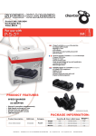
Getting Started Guide
2OO9 Edition
CONTROL
MICROSYSTEMS
48 Steacie Drive n Kanata, Ontario Canada K2K 2A9
Telephone: 613-591-1943 n Facsimile: 613-591-1022
Technical Support: 888-226-6876 (888-2CONTROL)
SCADA products ... for the distance
Getting Started Guide
2OO9 Edition
ClearSCADA Getting Started Guide
©2008 Control Microsystems Inc.
All rights reserved.
Printed in Canada.
Trademarks
ClearSCADA is a registered trademark of Control Microsystems Inc.
All other product names are copyright and registered trademarks
or trade names of their respective owners.
2OO9 Edition
2OO9 Edition
i
ii
Table of Contents
Appendix A: ClearSCADA Typical Install . . . . . . . . . . . . . . . . . . . . . . . . 28
1
Appendix B: Installing ViewX Client Only . . . . . . . . . . . . . . . . . . . . . . . 39
Getting Started Procedure . . . . . . . . . . . . . . . . . . . . . . . . . . . . . . . . . 2
Recommended PC Configurations and System Requirements . . . . . . . . . 2
ClearSCADA Demonstration Version . . . . . . . . . . . . . . . . . . . . . . . . . . 3
Installing ClearSCADA Demonstration Version . . . . . . . . . . . . . . . . . . 4
Going Through the ClearSCADA Presentation Tutorial . . . . . . . . . . . . . . . 7
Tutorial: My First Project (Using internal/simulated points) . . . . . . . . . . 9
Login to ViewX . . . . . . . . . . . . . . . . . . . . . . . . . . . . . . . . . . . . . . . 9
Create a New Group . . . . . . . . . . . . . . . . . . . . . . . . . . . . . . . . . . 10
Rename the Mimic . . . . . . . . . . . . . . . . . . . . . . . . . . . . . . . . . . 10
Create an Internal Analog Point . . . . . . . . . . . . . . . . . . . . . . . . . . 10
Drag the Point onto the Mimic . . . . . . . . . . . . . . . . . . . . . . . . . . . 12
Put the Mimic into RUN Mode and Control the Point . . . . . . . . . . . . . . . 13
Display the Historic Trend . . . . . . . . . . . . . . . . . . . . . . . . . . . . . . 14
Display the Historic List . . . . . . . . . . . . . . . . . . . . . . . . . . . . . . . 14
Change the Point’s Alarm Limits to Trigger an Alarm . . . . . . . . . . . . . 14
View the Alarms . . . . . . . . . . . . . . . . . . . . . . . . . . . . . . . . . . . . 15
Action an Alarm . . . . . . . . . . . . . . . . . . . . . . . . . . . . . . . . . . . . 16
Using ViewX Help . . . . . . . . . . . . . . . . . . . . . . . . . . . . . . . . . . . . . 17
Tutorial: SCADAPack Modbus Driver (using live I/O) . . . . . . . . . . . . . . . 18
Login to ViewX . . . . . . . . . . . . . . . . . . . . . . . . . . . . . . . . . . . . . 18
Create two New Groups . . . . . . . . . . . . . . . . . . . . . . . . . . . . . . . 18
Create a SCADAPack Modbus Direct Channel . . . . . . . . . . . . . . . . . . 18
Create a SCADAPack Modbus Direct Outstation Set . . . . . . . . . . . . . . 19
Create a SCADAPack Modbus SCADAPack Direct Outstation . . . . . . . . . 20
Create two SCADAPack Modbus Analog Input Points . . . . . . . . . . . . . 20
Create two SCADAPack Modbus Digital Input Points . . . . . . . . . . . . . 20
Create two SCADAPack Modbus Digital Output Points . . . . . . . . . . . . 21
Drag Items to the Default Mimic . . . . . . . . . . . . . . . . . . . . . . . . . . 22
Put the Mimic into Run Mode and Display a Historic Trend . . . . . . . . . 22
Adding an Alarm List to the Mimic . . . . . . . . . . . . . . . . . . . . . . . . . 23
Create a Trend . . . . . . . . . . . . . . . . . . . . . . . . . . . . . . . . . . . . . 25
Copying Trend Data to Microsoft Excel . . . . . . . . . . . . . . . . . . . . . . 26
Create a Template . . . . . . . . . . . . . . . . . . . . . . . . . . . . . . . . . . . 27
Create an Instance . . . . . . . . . . . . . . . . . . . . . . . . . . . . . . . . . . 27
Appendix C: Running WebX Client . . . . . . . . . . . . . . . . . . . . . . . . . . . 31
Welcome to ClearSCADA iii
Appendix D: Troubleshoot ClearSCADA Installation . . . . . . . . . . . . . . . . . 34
Appendix E: Re-start ClearSCADA Server . . . . . . . . . . . . . . . . . . . . . . . 34
Appendix F: Re-start ViewX . . . . . . . . . . . . . . . . . . . . . . . . . . . . . . . 35
Appendix G: Configuring the ClearSCADA Server to Start Automatically . . . . 35
Appendix H: ClearSCADA Uninstall Procedure . . . . . . . . . . . . . . . . . . . . 37
Appendix I: The Server Icon . . . . . . . . . . . . . . . . . . . . . . . . . . . . . . . 38
Appendix J: Licensing ClearSCADA . . . . . . . . . . . . . . . . . . . . . . . . . . . 39
Hardware License . . . . . . . . . . . . . . . . . . . . . . . . . . . . . . . . . . . . 39
Software License . . . . . . . . . . . . . . . . . . . . . . . . . . . . . . . . . . . . 40
Upgrading your License . . . . . . . . . . . . . . . . . . . . . . . . . . . . . . . . 41
Troubleshooting . . . . . . . . . . . . . . . . . . . . . . . . . . . . . . . . . . . . . . 42
iv
Welcome to ClearSCADA
Welcome to ClearSCADA, Control Microsystems’ SCADA system software.
ClearSCADA is a powerful client-server SCADA system with:
nOnline configuration including mimics (graphic representation), trends,
communications objects, points, schedules, reports, etc.
n Built-in, fully featured historian.
n OPC and ODBC support at both the client and server.
n Web server and IT integration features.
n Query-based lists of database items.
n IEC 6-1131 programming language support.
This document is meant to be a guide to help new users install, configure,
program and operate ClearSCADA in a timely fashion. It is not meant as a
substitute for the ClearSCADA User’s Manual, but rather as a companion to this
manual. A strong background in both programmable logic controllers (PLC)
and personal computers (PC) using Windows is highly recommended. If any
problems arise during the setup, it may be necessary to then consult the
ClearSCADA User’s Manual or call the Control Microsystems Technical Support
Department for assistance.
Technical Support: North America
(Available Monday to Friday 8:00 am– 6:30 pm Eastern Time).
Toll free within North America: 1-888-226-6876 (1-888-2CONTROL)
Direct: 1 (613) 591-1943
Fax: 1 (613)-591-1022
[email protected]
Technical Support: Europe
(Available Monday to Friday 9:00 am– 5:00 pm Central European Time).
Direct: 31 (71) 579 1650
Fax: 31 (71) 532 4539
[email protected]
Technical Support: Australia
(Available Monday to Friday 8:30 am– 5:30 pm AEST)
Direct: +61 2 4979 1899
Fax: +61 2 4954 4336
[email protected]
1
Getting Started Procedure
The getting started guide shows you how to:
n Install ClearSCADA Demonstration Version or Licensed Version
n Start the ClearSCADA Server
n Run ViewX
n Perform basic ClearSCADA actions using our Tutorial
n Access ClearSCADA help
Recommended PC Configurations and System Requirements
ClearSCADA can be installed on computers using the following operating
systems:
32 bit
n Windows Vista SP1 (Ultimate and Business editions only)
n Windows Vista (Ultimate and Business editions only)
n Windows Server 2008
n Windows Server 2003 R2
n Windows Server 2003 SP1
n Windows Server 2003
n Windows XP Professional Edition SP1, SP2, SP2a, SP3
n Windows 2000 Server SP4
64 bit
n Windows Vista SP1 (Ultimate and Business editions only)
n Windows Vista (Ultimate and Business editions only)
n Windows Server 2008
n Windows Server 2003 R2
ClearSCADA also requires the following software packages to be installed:
nMicrosoft Internet Explorer 6 or Internet Explorer 7 (Other browsers are
not supported)
n Microsoft Windows Installer 3.0 or later
For specific hardware requirements for different types of systems, point
counts etc., please refer to the ClearSCADA help available on the ClearSCADA
Install CD:
1.Navigate to CD:\ClearSCADA.
2.Open the file ViewX.chm (this is the ClearSCADA help file).
3.Using the tree view on the left hand side, navigate to Core Reference ->
Server Administration -> Welcome to the Server Administration Guide ->
Operational Limitations.
2
4.The page “Recommended PC Configurations” provides information on the
types of PCs required for typical system sizes.
5.For further advice, please contact Control Microsystems.
ClearSCADA Demonstration Version
When installing ClearSCADA for the first time, it is recommended that you
install the Full (Recommended) Version. The Full (Recommended) Version
installs a subset of common drivers and core functionality of the ClearSCADA
software and ViewX client as well as the following:
n Control Microsystems Overview Tutorial
n Sample Projects
n Symbol Library
The Demonstration version of ClearSCADA does contain some limitations as
compared to the fully licensed version of ClearSCADA. These include:
nThe ClearSCADA Server will run for 2 hours at a time, then automatically
shut down.
nThe ClearSCADA Server will allow you to connect 2 ViewX clients, 1 OPC
client, 1 Data access client and 2 Web clients. If you purchase a license
for ClearSCADA, it will define the number of clients that can attach to your
server.
nYou will not be able to configure 2 or more ClearSCADA Servers in a
redundant configuration in Demonstration Mode. If you wish to evaluate
ClearSCADA in a redundant configuration then we suggest that you
discuss this with your ClearSCADA distributor.
nThe ClearSCADA Server evaluation version is configured to run in manual
mode. It must be manually started after each restart of the workstation.
(The licensed version is normally set to restart automatically whenever
the PC boots up).
See Appendix D for details on configuring the ClearSCADA Server to run
automatically on startup.
See Appendix J for details on requesting and installing a ClearSCADA license.
3
Installing ClearSCADA Demonstration Version
Before beginning the installation, please ensure the following:
n You are logged onto your workstation with administrator privileges
n All firewalls are turned off (i.e. Norton, ZoneAlarm, BlackICE, etc)
n All other applications are closed
To install the ClearSCADA Demonstration Version:
1.Insert the ClearSCADA CD into your computer’s CD-ROM drive. The CD-ROM
auto-run program displays a splash screen on your computer.
If the splash screen is not displayed automatically, use Windows Explorer to
browse the ClearSCADA CD-ROM. Double-click on the setup file.
2.Select the Install ClearSCADA option.
The ClearSCADA Setup Wizard is displayed. It guides you through the
installation process.
4
3.When you reach the Choose Setup Type scren, select Full (Recommended)
and then select the Install button.
4.ClearSCADA will prompt you to create a username and password for the
Super User account. Enter a username and password. The Super User has
security privileges above and beyond all other users on the system
6.The ClearSCADA Server will start, the ViewX client will start and the
example database (with sample programs and overview tutorial) will be
imported. (This may take a minute or two, please be patient).
You should now be running the ClearSCADA Server. This is indicated by
the presence of the blue Icon in the system tray (lower right corner of the
screen). If this icon is not present, or is another color, the ClearSCADA Server
is not running properly. If the server is not running properly please refer
to Appendix D - Troubleshoot ClearSCADA Installation at the back of this
document.
You should also be running the ViewX client as indicated in the screen shot
below. Please note that the demo projects in the Demonstration Version will
trigger system alarms resulting in an audible alarm bell. To Silence the alarm,
right click on the large red ‘5’ button (this number may be different on your
screen) in the lower left corner of the screen and select Disable Bell.
5.The ClearSCADA Setup Wizard will guide you through the remainder of the
install procedure. When complete, select the Finish button.
5
6
Two new shortcuts have been added to your desktop.
The ClearSCADA Service Manager is used for manually starting and stopping
the ClearSCADA Server.
The following login details screen appears:
Use the Sales login as shown.
The ViewX shortcut may be used to launch the ViewX client for any
subsequent ClearSCADA evaluation sessions.
Again, select ‘Presentation’ and the following Main Menu appears:
Going Through the ClearSCADA Presentation Tutorial
If this is your first time working with ClearSCADA, it is recommended that you
step through each page in the tutorial to get an overview of the software and
its features.
In ViewX click on Presentation
Selecting the “Forward” arrow (circled above) cycles you through the screens
associated with the ‘Design’ column. After the last screen, the arrow takes
you back to this Main Menu. To cycle through the screens associated with
each column individually, select the button at the top of each column.
7
8
Some items inside each of the screens have links to other screens as shown
by the colored circles below. Move the cursor over an item and if it changes
into a hand symbol, click to open that screen.
Note: Using the ‘Sales’ Log in allows the user to simply view the details of the
Presentation. Using the ‘Eng’ Log in allows the user to make some changes
to the configuration. If this is your first time working with ClearSCADA, we
recommend that you use the ‘Sales’ Log in.
Tutorial: My First Project (Using internal/simulated points)
This section is designed to introduce you to the ClearSCADA environment
using internal/simulated I/O points and take you step by step through a
sample configuration. If you have a SCADAPack RTU available, and wish to
configure a first project using live I/O points; please see the next Tutorial:
SCADAPack Modbus Driver (using live I/O). Please note that this tutorial is
introductory in nature only, and is not intended as a ClearSCADA training
course. In this tutorial you learn how to:
n Add groups and database objects,
n Configure an object.
n Use drag and drop on Mimics.
n View Trends.
n View and action alarms.
Login to ViewX
1.Start the ClearSCADA Server and the ViewX client.
2.In ViewX, from the top menu select File | Log On.
3.Enter ‘Eng’ for the Username and hit the OK button.
9
Create a New Group
1.Right click on the ‘Main’ icon and select New | Group | Group.
2.Name this group ‘MyFirstTest’.
Rename the Mimic
1.Double-click on ‘MyFirstTest’ so that the ‘Default’ Mimic is displayed below
it in the list.
2.Right-click on ‘Default’ and, from the menu that appears, select ‘Rename’.
3.Type ‘MtestPlant’. The Mimic is now renamed.
Create an Internal Analog Point
1.Right click on the MyFirstTest group and select New | Internal | Analog
Point and name it ‘InternalWaterLevel’.
2.Double-click on ‘InternalWaterLevel’ to open its ‘Properties’ dialog.
3.Select the ‘Historic’ tab and check the ‘Enabled’ box.
10
4.From the top menu select File | Save (or click on the ‘Save’ icon from the
icon bar below the top menu bar). Close the ‘InternalWaterLevel’ Properties
dialog by clicking on the ‘X’ in the top right corner of the dialog.
Drag the Point onto the Mimic
1.Double-click on ‘MtestPlant’ to open the Mimic.
2.Select ‘InternalWaterLevel’, left click (hold) and drag ‘InternalWaterLevel’
to the ‘MtestPlant’ Mimic. Release the mouse button and a menu appears.
Select Value | Formatted Value from the menu.
3.Repeat Step 2 but select Value | Vertical Bar | Up from the menu.
The Mimic screen should look like this:
11
12
Put the Mimic into RUN Mode and Control the Point
1.Put the Mimic into RUN Mode by clicking the ‘Design Mode’ icon on the icon
menu bar .
The grid pattern on the Mimic is hidden and the objects are both blank.
2.Move your mouse over either of the objects on the Mimic. The cursor
changes from an arrow to a hand symbol. While the cursor is a hand
symbol, left-click and a menu appears.
3.Select ‘Hand Control’ from the menu and then enter ‘10’ into the ‘Hand
Control’ dialog and click ‘OK’.
Display the Historic Trend
1.Move your mouse over either of the objects on the Mimic, left-click and,
from the menu, select ‘Display Historic Trend’. The Historic Trend for
‘InternalWaterLevel’ appears.
The Historic Trend displays the data values for an object over a period of time
as a graph.
Display the Historic List
1.Move your mouse over either of the objects on the Mimic, left-click
and, from the menu, select ‘Display Historic List’. The Historic List for
‘InternalWaterLevel’ appears.
The ‘Formatted Value’ field displays ’10.00’ and the Vertical Bar is filled in
black at the bottom.
4.Repeat Steps 2 and 3, three more times, changing the ‘Value’ to ‘15’,
‘20’ and ‘80’. The changed values are displayed on the Mimic after each
change.
13
The Historic List displays the data values for an object over a period of time
as a list.
Change the Point’s alarm Limits to Trigger an alarm
You can change the value of an object to one that is outside its alarm Limits
(either too high or too low). When you do this, you will see how ViewX displays
alarms.
To change an object’s alarm Limits to trigger an alarm:
1.Double-click on ‘InternalWaterLevel’ to open its ‘Properties’ dialog.
14
2.Select the ‘Analog Point’ tab. In the ‘High High’ field, enter ‘90’ for ‘Limit’,
enter ‘alarm’ for ‘Severity’ and enter ‘High’ in the field to the right of
‘Severity’.
3.From the top menu select File | Save (or click on the ‘Save’ icon from the
icon bar below the top menu bar). Close the ‘InternalWaterLevel’ Properties
dialog by clicking on the ‘X’ in the top right corner of the dialog.
4.Go back to the Mimic screen and enter a value of ‘95’ for
‘InternalWaterLevel’ (see Steps 2 and 3 from Put the Mimic into RUN Mode
and Control the Point).
An alarm is now generated.
View the alarms
ViewX provides several different ways to view alarms on your system. You
can view alarms for:
n One object.
n The whole group.
To View all alarms for your system, either:
1.Select the All alarms button from the Operate toolbar.
Or
2.Press the F9 key.
The alarms List window is displayed.
15
To view alarms for a particular object either:
1.Right-click on ‘InternalWaterLevel’ and select ‘Display alarms’.
Or
2.Left-click on the object in the Mimic and select ‘Display alarms’.
The alarm List for ‘InternalWaterLevel’ is displayed.
Action an alarm
You can perform different actions on an alarm:
n Acknowledge – Acknowledge an alarm.
nAcknowledge with Comment – Acknowledge an alarm and associate it with
a brief text description.
n Response – Record a response to an alarm without acknowledging it.
n Remove – Delete an alarm (higher level users only).
nRemove with Comment – Delete an alarm and associate the event that
is logged for the deletion with a brief text description (higher level users
only).
nDisable – Disable (suppress) an alarm. You may want to disable an alarm
when a faulty device is causing nuisance alarms, or a device has been
decommissioned (higher level users only).
To action an alarm either:
1.Left-click on an ‘InternalWaterLevel’ object in the Mimic and select
‘Acknowledge alarms’ from the menu.
Or
2.Right-click on the alarm in the alarm List and select ‘Acknowledge’ from the
menu.
Or
3.Right-click on the alarm in the alarm Banner (at the bottom of the screen)
and select ‘Acknowledge’ from the menu.
16
The colour of the alarm changes and it stops flashing.
Using ViewX Help
ViewX includes an online help feature that you can use to learn about various
aspects of ClearSCADA system configuration and operation.
ViewX Help includes:
nClearSCADA Guide to ViewX and WebX Clients – A guide to using the
ClearSCADA Client Interfaces. Explains how to use displays such as
Mimics, Trends and Lists, and how to monitor alarm and event activity
using both ViewX and WebX Clients.
nCore Reference Suite – Guides for high-level users for configuring the
ClearSCADA database, server, and ClearSCADA Client components such as
Mimics and Trends.
n Driver Reference Suite – Technical guides for configuring device drivers.
n Technical Reference Suite – Technical guides for high-level users.
To access ViewX Help:
1.Either:
Press the F1 key.
Or:
i. Select the Help menu.
A sub-menu is displayed.
ii. Select the Contents option.
The ViewX Help window is displayed.
2.Either:
i. Select the Contents tab.
ii. Navigate the tree structure to find the topic you want.
iii.Select the topic name.
Or:
17
i. Select the Search tab.
ii. Enter a word you want to search for, e.g. Mimic.
iii.Select the List Topics button.
iv.Double-click on the required topic name.
The Help topic you want is displayed in the right pane of the Help window.
Tutorial: SCADAPack Modbus Driver (using live I/O)
This section walks you through the steps to configure a serial connection to
a SCADAPack controller, add groups and database objects, create and view
trends, view and action alarms. Please note that this tutorial is introductory
in nature only. For detailed ClearSCADA training please contact Control
Microsystems. This exercise assumes the following:
n The serial port of the SCADAPack controller is set to Modbus address 1.
n TelePACE firmware is loaded into the SCADAPack controller.
nA standard Register Assignment is configured in the SCADAPack.
To configure a SCADAPack Modbus Driver in ClearSCADA:
Login to ViewX
1.Start the ClearSCADA Server and the ViewX client.
2.In ViewX, from the top menu select File | Log On.
3.Enter ‘Eng’ for the Username and hit the OK button.
Create two New Groups
1.Right click on the ‘Main’ icon and select New | Group | Group.
2.Name this group ‘Serial Comms’.
3.Again, right click on the ‘Main’ icon and select New | Group | Group.
4.Name this group ‘Site’.
Note: If a setting or option isn’t listed below for editing, leave it at the default.
Create a SCADAPack Modbus Direct Channel
1.Right click on the Serial Comms group and select New | SCADAPack
Modbus | Direct Channel.
2.Hit ‘Enter’ (the default name ‘New Direct Channel’ is used).
3.Double-click on New Direct Channel to open its Properties dialog.
4.Select the ‘Connection’ tab. Set the ‘Port’ field to the appropriate serial port
on your PC (i.e. Com1, Com2, etc) along with the baud rate, data bits, etc, to
be the same as the settings in your SCADAPack.
18
Note: if a 3-wire cable is being used, set ‘Flow Control’ to ‘None’. If a standard
null modem cable is being used, set ‘Flow Control’ to ‘Hardware (RTS/CTS)’.
5.Select the ‘Channel’ tab and check the ‘In Service’ box.
6.Select the ‘Scan Parameters’ tab. Set the ‘Reestablishment Interval’ to be
10 seconds.
7.From the top menu select File | Save (or click on the ‘Save’ icon from
the icon bar below the top menu bar). Close the ‘New Direct Channel’
Properties dialog by clicking on the ‘X’ in the top right corner of the dialog.
Create a SCADAPack Modbus Direct Outstation Set
1. Right click on the Serial Comms group and select New | SCADAPack
Modbus | Direct Outstation Set.
2. Hit ‘Enter’ (the default name ‘New Direct Outstation Set’ is used).
3. Double-click on New Direct Outstation Set to open its Properties dialog.
4. S elect the ‘Outstation Set’ tab and check the ‘In Service’ box. In the
‘Channel’ field select the browse button and, from the ‘Reference’
dialog that appears, select ‘New Direct Channel’. Click ‘OK’ to close the
‘Reference’ dialog.
5. Select the ‘SCADAPack’ tab. Change the ‘Set Address’ to 1 (Note: this is NOT
the RTU station address).
6. Save and close the ‘New Direct Outstation Set’ Properties dialog.
19
Create a SCADAPack Modbus SCADAPack Direct Outstation
1.Right click on the Site group and select New | SCADAPack Modbus |
SCADAPack Direct Outstation.
2.Name this ‘ScPack’ and hit ‘Enter’.
3.Open the ‘ScPack’ Properties dialog.
4.Select the ‘SCADAPack’ tab and set the ‘Address’ to 1 (this IS the RTU
address).
5.Select the ‘Direct’ tab and check the ‘Promote when Displaying Points’ tab.
6.Select the ‘Outstation’ tab and check the ‘In Service’ box. In the ‘Outstation
Set’ field, select the browse button and select ‘New Direct Outstation Set’.
7 Save and close the ‘ScPack’ Properties dialog
Create two SCADAPack Modbus Analog Input Points
1.Right click on the Site group and select New | SCADAPack Modbus |
Analog Input Point and name it ‘AI 1’.
2.Open the ‘AI 1’ Properties dialog.
3.Select the ‘Analog Point’ tab and check the ‘In Service’ box. In the
‘Outstation’ field, hit the browse button and select ‘ScPack’. Set the
‘Address’ field to 30001 (this is the first AIN point). Set the ‘Retrieval
Interval’ to ‘Interval 1’.
4.Select the ‘Historic’ tab and check the ‘Enabled’ box. Set the ‘Offset’ field
to ‘S - 55S (current second minus 55 seconds). Set the ‘Interval’ to 1M (1
minute).
5.Save and close the ‘AI 1’ Properties dialog.
6.With ‘AI 1’ selected, (from the top menu) select Edit | Copy. Again from the
top menu select Edit | Paste. A copy of ‘AI 1’ is pasted below ‘AI 1’.
7. Change the name of the copy to ‘AI 2’.
8.Open the ‘AI 2’ Properties dialog. From the ‘Analog Point’ tab set the
‘Address’ to 30002.
9.Save and close the ‘AI 2’ Properties dialog.
Create two SCADAPack Modbus Digital Input Points
1.Right click on the Site group and select New | SCADAPack Modbus | Digital
Input Point and name it ‘DI 1’.
2.Open the ‘DI 1’ Properties dialog.
20
3.Select the ‘Digital Point’ tab and check the ‘In Service’ box. In the
‘Outstation’ field, hit the browse button and select ‘ScPack’. Set the
‘Address’ field to 10001 (this is the first DIN point). Set the ‘Retrieval
Interval’ to ‘Interval 1’. Scroll down the screen to the ‘States’ section. For
‘State 1’ set ‘Severity’ to ‘alarm’ and ‘High’.
4.Select the ‘Historic’ tab and check the ‘Enabled’ box. Set the ‘Offset’ field
to ‘S - 55S (current second minus 55 seconds). Set the ‘Interval’ to 1M (1
minute).
5.Save and close the ‘DI 1’ Properties dialog.
6.With ‘DI 1’ selected, (from the top menu) select Edit | Copy. Again from the
top menu select Edit | Paste. A copy of ‘DI 1’ is pasted below ‘DI 1’.
7. Change the name of the copy to ‘DI 2’.
8.Open the ‘DI 2’ Properties dialog. From the ‘Digital Point’ tab set the
‘Address’ to 10002.
9.Save and close the ‘DI 2’ Properties dialog.
Create two SCADAPack Modbus Digital Output Points
1.Right click on the Site group and select New | SCADAPack Modbus | Digital
Output Point and name it ‘DO 1’.
2.Open the ‘DO 1’ Properties dialog.
3.Select the ‘Digital Point’ tab and check the ‘In Service’ box. In the
‘Outstation’ field, hit the browse button and select ‘ScPack’. Set the
‘Address’ field to 00001 (this is the first DOUT point. If using a 5604 lower
I/O module, use address 00003). Set the ‘Retrieval Interval’ to ‘Interval 1’.
4.Select the ‘Control’ tab. Check the ‘Enabled’ boxes beside ‘Action 1’ and
‘Action 2’.
5.Save and close the ‘DO 1’ Properties dialog.
6.Copy and Paste ‘DO 1’. Name the copy ‘DO 2’.
7.Open the ‘DO 2’ Properties dialog. From the ‘Digital Point’ tab set the
‘Address’ to 00002 (or 00004 is using a 5604).
8.Save and close the ‘DO 2’ Properties dialog.
NOTE: The DO addresses should be relative to the hardware you have. If using
a 5601, then there is no problem BUT if you use a 5604 (where the DIs and
DOs are common) then you should make the DO addresses correspond to the
3rd and 4th outputs (00003 & 00004).
21
Drag Items to the Default Mimic
1.In the Site group, double click on ‘Default’ to open the Default Mimic.
2.Select AI 1, left click (hold) and drag AI 1 to the Default Mimic. Release the
mouse button and a menu appears. Select ‘Name’ from the menu.
3.Repeat Step 2 but select Value | Formatted Value from the menu.
4.Repeat Step 2 but select Value | Vertical Bar | Up from the menu.
5.Repeat steps 1 to 4 for AI 2.
6.Repeat steps 2 and 3 for each of the digital points: DI 1, DI 2, DO 1 & DO 2.
7. Repeat step 6 but select State from the menu.
8.(Optional) - If you wish, repeat step 2 above and insert ‘Quality’ and ‘Last
Updated’ (from the menu) for AI 1 and ‘Alarm State’ for DI 1.
9.Select File | Save from the main menu to save your changes.
Put the Mimic into Run Mode and Display a Historic Trend
You can now take a look at some real-time data coming from the SCADAPack,
via the Mimic you just populated. Put the Mimic into RUN Mode by clicking the
‘Design Mode’ icon on the icon menu bar .
Note: By default, when a Mimic is in Design Mode, the Mimic is shown with its
grid turned on like this:
When the Mimic is put into RUN Mode, the Mimic’s grid is hidden like this:
Each of the ‘Formatted Value’ fields in the Mimic should be updating with
values from the SCADAPack Controller. Adjust values for AI 1, AI 2, DI 1 and DI
2.You should see their values change on the Mimic.
If you click on an item in the Mimic, an object menu for that point appears like
this:
22
Place your mouse over the ‘Formatted Value’ filed for ‘AI 1’, left-click and
select ‘Display Historic Trend’. A temporary trend object appears on the
screen.
Historic Trends may be displayed for each of the other Analog and Digital
Points on the Mimic.
Close the trend window(s) when you are finished observing the data.
Adding an Alarm List to the Mimic
An Alarm List may be added for displaying alarms right on the Mimic.
1.Put the Mimic back into Design Mode .
2.From the top menu, select Insert | Alarm List.
3.In a free area on the Mimic, hold the left mouse button and drag towards
the open area. The outline of a rectangle should appear. Release the mouse
button and the Alarm List should appear.
4.Put the Mimic back into RUN Mode.
23
5.Disconnect the serial cable from the SCADAPack. After a few seconds a
‘Communications state – Failed’ alarm appears in the list. Also, the values
for all fields in the Mimic turn from Black to Violet, indicating a loss of
communication.
6.Reconnect the Serial Port cable to the SCADAPack. Again, after a few
seconds the alarm changes from Red to Green indicating that the alarm
is cleared (but not acknowledged) and all fields that had turned Violet will
turn Black (indicating good communication).
7.To acknowledge the ‘Communication state – Failed’ alarm, place your
mouse over the alarm (either in the Alarm List or in the alarm banner at the
bottom of the screen), left click and select ‘Acknowledge’ from the list. The
alarm disappears from the list.
The Alarm List may be filtered to show only alarms that pertain to the Site
group.
1.While the Mimic is in RUN mode, click on the button on the bottom right
corner of the Alarm List. A menu appears; select ‘Filter’.
24
2.In the ‘Areas’ section, click the ‘Add’ button. Type: Site and click ‘OK’.
3.Click ‘OK’ to close the ‘Filter’ dialog. Now the Alarm List only shows alarms
directly related to the Site group.
Create a Trend
A graphic trend object may be created to display historical data for one or
more points.
To create a Trend object that may be reused or embedded into a mimic:
1.Right click on the Site group and select New | Trend. Leave it as the default
name ‘New Trend’.
2.Double-click on ‘New Trend’ to open it.
3.Place your cursor below the X-axis of the trend, right-click and select ‘Edit’
from the menu.
4.From the ‘Edit X Axis’ dialog, set ‘Offset’ to ‘M – 4M’ and set ‘Interval’ to ‘5M’.
Select OK.
5.Drag ‘AI 1’ over to the trend (just as you did when you dragged it to the
Mimic) and select ‘Raw Historic Trace’ from the menu.
6.Add a second Y axis scale to the trend. Right-click at the right edge of the
trend window and select ‘Add Y Axis’. Change the name of the scale to ‘Y
Axis Rt’ and select Right in the ‘Side’ control. Press the OK button.
7.Drag and drop DI 1 from the data bar tree onto the trend window, and
select Raw Historic Trace in the resulting menu.
25
8.Double click on Site.DI 1 in the trend key below the trend.
a. Select ‘Y Axis Rt’ in the Y Axis control, and change the Style to ‘Step Last’.
If you make changes to the analog or digital input, they are displayed on this
trend. You can zoom in on these if you have mouse with a scroll wheel. Simply
place the mouse near the bottom outside edge of the Y-Axis and scroll the
mouse wheel. If you do not have a mouse with a scroll wheel you may still
zoom in and out by right-clicking on the Y-Axis and selecting either ‘Zoom In’
or ‘Zoom Out’.
Copying Trend Data to Microsoft Excel
Data from the trend may be copied to Microsoft Excel for data analysis/
presentation purposes.
1.Make sure you have some varying data visible by toggling the digital input
and adjusting the analog input signal(s).
2.Take the Trend out of continuous mode. Right-click on the X-Axis and, from
the menu, un-check ‘Continuous’. The trend stops updating.
3.From the File menu select Edit | Copy.
4.Open Microsoft Excel. In Excel, select Edit | Paste. The data from all four
traces on the Trend is now copied to the Excel spreadsheet.
For additional information on creating and using trends objects, please see
ClearSCADA Help | Core Reference | Trends.
26
Create a Template.
A Template allows a configuration (such as our Site group) to be used in
multiple instances whereby only small changes need to be made for each
instance. This is useful where you have several controllers that all use the
same configuration, but have different station addresses. Since most of the
configuration for each instance is already set up in the template, this can
save a lot of time in configuring the system.
To create a Template:
1. Right click on the Site group and select Convert To | Group Template.
The Site Group folder turns burgundy indicating that it is now a Template.
Create an Instance
Now that a Template has been created, you can create several instances that
are based on that template.
To create an Instance:
1.Right-click on ‘Main’ and select New Instance | Site. Name this ‘Site ABC’.
2.Double-click on ‘Site ABC’ and notice it contains all the same I/O points as
‘Site’. Also note that the Default Mimic contains the same objects.
The ‘Site ABC’ folder is green indicating that it is an Instance.
3.Right-click on ‘Main’ and select New Instance | Site. Name this ‘Site XYZ’.
4.Open the Default Mimic from the ‘Site’ Template.
5.Drag ‘ScPack’ onto the mimic and select ‘State’ from the menu. Save this
Mimic.
27
6.Open the Default Mimics from both ‘Site ABC’ and ‘Site XYZ’ and notice that
the ‘ScPack’ State has been added to both of them.
Appendix A: ClearSCADA Typical Install
If you are installing ClearSCADA on multiple workstations and you do not
wish to install the sample programs, you may choose the Typical Install. The
Typical Install allows you to select which components of the ClearSCADA
software you wish to install:
nFull Client – Uses the ViewX Client for viewing Mimics, Trends, Lists and
Reports, configuring the database, and viewing data.
nWeb Client – Optional WebX Client that allows you to use a web browser to
access the ClearSCADA database from any location via the Internet.
n Server – Installs the ClearSCADA Server on your workstation.
nData Access – Third party tools, such as Microsoft Access, that can
collect data from or push data to the ClearSCADA Server via ODBC. OPC and
Automation Interface clients may also connect to the ClearSCADA Server.
To install the ClearSCADA Licensed Version:
1. Complete steps 1 and 2 from the section Installing ClearSCADA
Demonstration Version above.
28
2. W
hen you reach the Choose Setup Type screen, select Typical and then
select the Next button.
5.The ClearSCADA Setup Wizard guides you through the remainder of the
install procedure. When complete, select the Finish button
3.From the Typical Install screen select Server and Clients and select the
Next button.
Appendix B: Installing ViewX Client Only
The ViewX client may be installed on a workstation separately from the
ClearSCADA Server. This allows the ClearSCADA Server to run on one
workstation while allowing a user to access the ClearSCADA Server remotely,
using ViewX, from another workstation.
To install only the ViewX client:
1.Complete steps 1 and 2 from the section Installing ClearSCADA
Demonstration Version above.
2.When you reach the Choose Setup Type screen, select Typical and then
select the Next button.
4.From the Custom Setup screen select the Next button.
29
30
3.Select the Clients button.
4.The ClearSCADA Setup Wizard guides you through the remainder of the
install procedure. When complete, select the Finish button
Appendix C: Running WebX Client
The WebX client allows a remote connection to the ClearSCADA Server via the
Internet.
This allows a user to remotely monitor a ClearSCADA configuration from
anywhere they can find an Internet connection
To run the WebX client:
1.Open your web browser (i.e. Microsoft Internet Explorer)
2.Type the IP address of the workstation that is running the ClearSCADA
Server in the address field of the browser. The ClearSCADA home page is
displayed.
31
3.Click ‘Database’ from the top menu and the Groups list appears.
4.Click on ‘Site’ and the list of points in the Site Group is displayed.
32
You may view any of the Lists, Points, Mimics, Trends, alarms, Events, etc for
the Group. Use the browser’s Forward and Back arrows to navigate between
screens.
Appendix D: Troubleshoot ClearSCADA Installation
The installation may take a few minutes, and is completed automatically
unless:
nThere is insufficient disk space. If you have this problem, you need to
make more disk space available by deleting files or installing additional
disk space.
nThe source files cannot be found. If this occurs, you need to ensure that
ClearSCADA can access the installation files on the ClearSCADA CD-ROM.
nThere has been an error in the installation procedure. If this occurs, you
should contact Control Microsystems.
nYour Microsoft Windows user account does not have the administrator
level privileges. Refer to your Microsoft Windows documentation for more
information.
nYou have a software firewall running during the installation that interferes
with the installation.
Appendix E: Re-Start ClearSCADA Server
When ClearSCADA is installed, it creates two shortcuts on the desktop. One of
the shortcuts is used to launch the ClearSCADA Service Manager.
The ClearSCADA Service Manager is used to Start and Stop the ClearSCADA
Server.
From the desktop, double-click on the ClearSCADA Service Manager.
To start the Server, click on the Start button. If the Server is running and you
wish to stop it, click on the Stop button.
When the ClearSCADA Server is running, a blue icon appears in the system
tray (lower right corner of the screen. If this icon is not present, or is another
color, the ClearSCADA Server is not running properly.
If ViewX is not running at this point, re-start ViewX (see Re-Start ViewX
below).
33
34
Appendix F: Re-Start ViewX
The ViewX client allows graphic configuration and control of the ClearSCADA
Server.
From the desktop, double-click on the ViewX icon.
mode. In automatic mode, any time the workstation is restarted, the
ClearSCADA Server starts up automatically.
To put the ClearSCADA Server Service into automatic mode:
1.From Windows, select Start | Settings | Control Panel
2.Double Click on ‘Administrative Tools’ and then double click on ‘Services’.
3.Locate ‘ClearSCADA Server’ in the list
4.Double-click on ‘ClearSCADA Server’.
If this is your first time working with ClearSCADA, it is recommended that you
step through each page in the tutorial to get an overview of the software and
its features.
(See Going Through the ClearSCADA Presentation Tutorial above)
Please note that after re-start of the server and ViewX, the opening page
shown above can be reached by the following steps:
1.Log on as Eng using the menu File | Log On. Enter ‘Eng’ as the user name
and leave the password blank.
2.Expand MAIN in the database tree control
3.Double-click on Opening Page to view the mimic shown above.
Appendix G: Configuring the ClearSCADA Server
to Start Automatically
The ClearSCADA Server runs as a Service in the Windows OS. When you install
the Demonstration Version, the Service is configured in manual mode. In
manual mode, any time the workstation is restarted; the ClearSCADA Server
is not started automatically. The user must manually start the ClearSCADA
Server (see Start ClearSCADA Server section below).
If a Typical Installation is performed, the Service is configured for automatic
35
Select the drop down arrow from the ‘Startup type’ field and select
‘Automatic’.
5.Click the ‘Apply’ button and then the ‘OK’ button to close the dialog.
6.Close the Services dialog by clicking on the ‘X’ in the top right corner of the
dialog.
7. Close the ‘Administrative Tools’ dialog.
The ClearSCADA Server should now start up automatically the next time the
workstation is started.
36
Appendix H: ClearSCADA Uninstall Procedure
Note: Before doing the uninstall steps:
1.If you want any of your database saved, do it now. Export what you want to
keep from ViewX.
2.If you have been issued a ClearSCADA soft license file for your computer,
locate it and save it somewhere safe. It will be a .lic file.
To completely uninstall ClearSCADA from your workstation:
n Stop the ClearSCADA Server and close ViewX.
Note: Fresh installations and upgrades originating from ClearSCADA 2007
R1 and newer are installed under the C:\Documents & Settings folder.
ClearSCADA upgrades originating from ClearSCADA 2007 R0.1 or older will
continue to install in the C:\Program Files folder.
If you have the folder C:\Program Files\Control Microsystems\ClearSCADA,
please follow Procedure 2, otherwise please follow Procedure 1.
Procedure 1 (For ClearSCADA installed under C:\Documents & Settings)
1.Remove any system DSN. Do this only if you manually added the DSN
into your computer. Check in Control Panel | Administrative Tools | Data
Sources (ODBC) on the ‘System DSN’ tab. Delete any entry using the
ClearSCADA driver.
2.Un-install from Windows using Control Panel | Add/Remove Programs.
Remove any ClearSCADA version installed.
3.Delete the install and database directory. ClearSCADA is in C:\Documents
& Settings\All Users\Application Data\ControlMicrosystems\ClearSCADA.
4.Delete all the registry keys: HKEY_LOCAL_MACHINE\software\serck
controls\scx6.
5.Delete the directory C:\Documents & Settings\<user>\Local Settings\
Application Data\ControlMicrosystems\ClearSCADA (you are looking to
remove the directory where ViewX Global Settings.dat is).
This may be difficult to locate if you don’t have the ‘show hidden files’ option
turned on. Open a Windows Explorer dialog and, from the top menu, select
Tools | Folder Options. Select the ‘View’ tab and ensure the ‘show hidden files
and folders’ radio button is checked.
Procedure 2 (For ClearSCADA installed under C:\Program Files)
1.Remove any system DSN. Do this only if you manually added the DSN
into your computer. Check in Control Panel | Administrative Tools | Data
Sources (ODBC) on the ‘System DSN’ tab. Delete any entry using the
ClearSCADA driver.
37
2.Un-install from Windows using Control Panel | Add/Remove Programs.
Remove any ClearSCADA version installed.
3.Delete the install directory. ClearSCADA is in C:\Program Files\Control
Microsystems\ClearSCADA.
4.Delete the database directory. Located on the C: drive, it is C:\
ClearSCADADB.
5.Delete all the registry keys: HKEY_LOCAL_MACHINE\software\serck
controls\scx6.
6.Delete the directory ..\Documents and Settings\All Users\Application
Data\Serck Controls (you are looking to remove the directory where ViewX
settings.dat is).
This may be difficult to locate if you don’t have the ‘show hidden files’ option
turned on. Open a Windows Explorer dialog and, from the top menu, select
Tools | Folder Options. Select the ‘View’ tab and ensure the ‘show hidden files
and folders’ radio button is checked.
Appendix I: The Server Icon
The ClearSCADA Server Icon is now a separate application and is not part of
the Server Service. The Server Icon may be launched separately from the
Server which means that the Server may be running but the icon may not be
visible.
Starting the Server Icon
If the ClearSCADA Server is set to start automatically as a service on PC
startup, the Server icon will appear as normal in the system tray. If, however,
the Server is not set to start automatically, the Server icon must be launched
separately. To launch the Server icon:
1.Click on Windows Start | All Programs | Control Microsystems ClearSCADA
|Server icon
2.Alternatively, the Server icon may be launched by browsing to:C:\
Program Files\Control Microsystems\ClearSCADA and double-clicking on
ServerIcon.
If the ClearSCADA Server is stopped, the Server icon will appear grayed out
like this:
If the ClearSCADA Server is running, the Server icon will appear blue like this:
38
Starting and stopping the ClearSCADA Server is performed in the same way
as previously done.
Stopping the Server Icon
The Server icon will not disappear when the ClearSCADA Server stops as was
previously the case. To stop (remove) the Server icon:
n Right-click on the Server icon and select Exit.
Note: This may only be performed if the ClearSCADA Server is stopped. If the
ClearSCADA Server is running, right-clicking on the Server icon will allow you
to shut down the ClearSCADA Server, but not remove the Server icon. Once
the server is shut down, you must right click again to remove the Server icon.
Appendix J: Licensing ClearSCADA
Once installed, when the ClearSCADA Server is started, it will run in demo
mode for a period of 2 hours. Once the 2 hour period has expired, the Server
will shut down. Changes to the database and historic (logged) data will not
be lost when this happens. A user simply needs to restart the server to
reestablish a connection to the database.
Demo mode differs from the Fully Licensed mode only in the run time period.
All other features of ClearSCADA are available and functional while in demo
mode.
Licensing ClearSCADA can be performed in one of following two ways:
n Hardware License (USB dongle)
n Software License (.lic file)
Hardware License
The USB key hardware license has the advantage of not being PC specific.
The key can be used on any PC running ClearSCADA which means a user may,
in effect, “take” their license with them.
The downside to the USB key hardware license is that once removed,
ClearSCADA reverts back to demo mode which means the USB key must
be inserted at all times in order for the license to be seen as ‘valid’ by the
ClearSCADA Server.
Hardware Licenses are typically shipped with the ClearSCADA CD at the time
of order.
39
To obtain a USB key hardware license, email your inquiry to: SCADACare@
controlmicrosystems.com:
Within one business day, you will receive a response to your email complete
with instructions of delivery.
Software License
The software license has the advantage of being permanently installed on
the PC; thereby ensuring that ClearSCADA will always be licensed on that
machine.
The downside to the software license is that it is hard coded to the PC’s
machine ID. Should a hardware configuration be made to the PC (i.e. adding
a new network card) that changes the PC’s machine ID, the software license
may become invalid and a new license will need to be installed.
A software license cannot be transferred from one PC to another. It is PC
specific.
To obtain a software license:
1.Start the ClearSCADA Server and right click on the “ClearSCADA Server icon”
in the system tray (lower right corner of screen). Select “License Details”
from the menu. Note the “Machine ID” number. To avoid transcription
errors, we suggest that you copy and paste this number into an email (see
step 2).
2.Email the following information to [email protected]:
n Machine ID (this should be copied and pasted from Step 1)
n License serial number (located on back of CD case)
Within one business day, you will receive a response to your email complete
with the required license file and instructions to activate your license.
To activate your software license for the server
nSave the attached license file to your computer (i.e. C:\Program Files\
Control Microsystems\ClearSCADA\license.lic)
n Start the Service Manager
n Right click on the server icon (in the system tray)
n Select License Details
n Browse to the license file
n Select file and click Open
To activate your license for the local (embedded) client:
nFrom the Start menu, select Programs, Control Microsystems ClearSCADA
– Configure ClearSCADA Connections. The ClearSCADA Client dialog will
appear.
40
Click on the Licenses... button. The Client Licensing dialog will appear.
Click on the browse button located to the right of the License File field.
Note: If odd characters exist in the License File field, delete them as they
prevent the file browser from being displayed.
n Browse to the license file located on the hard drive and click Open.
n In the Client Licensing dialog, click on Apply.
n Click on the OK button.
n Close the ClearSCADA Client dialog.
n (Re)start ViewX.
Note: the above steps are also used to activate the ViewX license on a remote
client.
Upgrading your License
Both the hardware and software licenses may be upgraded after they are
installed
Upgrading the USB key Hardware License
nFrom the Start menu, select Programs, Control Microsystems ClearSCADA,
Dongle Field Exchange Utility.
n Click on “Get Locking Code”
nSend this locking code and the Dongle serial number in a email to:
[email protected]
Once the email is received, our customer support group will reply with a new
unlocking code. Paste this code into the field below the “Get Locking Code”
field in the Field Exchange Utility.
Upgrading the Software License
Email the following information to [email protected]:
n Machine ID (see above)
n License serial number (located on back of CD case)
Within one business day, you will receive a response to your email complete
with the required license file and instructions to upgrade your license.
n
n
41
Troubleshooting
If any problems occur at any step in the procedure, review the pertinent
steps to ensure that they have been followed correctly. If you are unable to
resolve the problem, please contact the technical support department at
Control Microsystems for further assistance.
Toll Free Technical Support
Users in Canada and the United States may call our technical support
department free of charge. You will be connected to the nearest support
center in your time zone.
Technical Support: North America
(Available Monday to Friday 8:00 am– 6:30 pm Eastern time).
Toll free within North America: 1-888-226-6876 (1-888-2CONTROL)
Direct: 1 (613) 591-1943
Fax: 1 (613)-591-1022
[email protected]
Mailing Address: Control Microsystems
48 Steacie Drive
Kanata, Ontario, Canada
K2K 2A9
Technical Support: Europe
(Available Monday to Friday 9:00 am– 5:00 pm Central European Time).
Direct: 31 (71) 579 1650
Fax: 31 (71) 532 4539
[email protected]
Technical Support: Australia
(Available Monday to Friday 8:30 am– 5:30 pm AEST)
Direct: +61 2 4979 1899
Fax: +61 2 4954 4336
[email protected]
42