1
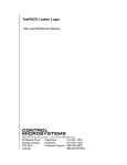
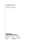
Control Microsystems Bluetooth User Manual Model 5913 Bluetooth Adaptor, type RJ-45 (Controller) Model 5914 USB (PC) Bluetooth CONTROL MICROSYSTEMS SCADA products... for the distance 48 Steacie Drive Kanata, Ontario K2K 2A9 Canada Telephone: 613-591-1943 Facsimile: 613-591-1022 Technical Support: 888-226-6876 888-2CONTROL 5913 and 5914 User and Reference Manual ©2007 Control Microsystems Inc. All rights reserved. Printed in Canada. Trademarks TeleSAFE, TelePACE, SmartWIRE, SCADAPack, TeleSAFE Micro16 and TeleBUS are registered trademarks of Control Microsystems Inc. All other product names are copyright and registered trademarks or trade names of their respective owners. 5913 and 5914 User and Reference Manual April 30, 2008 1 Table of Contents 1 OVERVIEW .................................................................................................... 3 2 IMPORTANT SAFETY INFORMATION ......................................................... 4 3 QUICK START GUIDE .................................................................................. 5 3.1 Install 5913 Serial Adaptor........................................................................ 5 3.2 Install 5914 USB Adaptor ......................................................................... 5 3.3 Install 5914 USB Adapter Software Driver ................................................ 5 3.4 Configure Bluetooth Connection ............................................................... 7 3.5 Configure Internal Laptop Bluetooth Connection .................................... 12 3.6 Configure application .............................................................................. 12 4 INSTALLATION ........................................................................................... 14 4.1 5913 Installation ..................................................................................... 14 4.2 5913 Serial Port Connections ................................................................. 15 4.3 Serial Port Communication Parameters ................................................. 16 4.4 5913 Dimensions and LEDs ................................................................... 16 4.5 5914 Connection .................................................................................... 16 5 MAINTENANCE ........................................................................................... 17 6 SPECIFICATIONS ....................................................................................... 18 6.1 6.1.1 6.1.2 6.1.3 6.1.4 5913........................................................................................................ 18 General ............................................................................................. 18 Communications................................................................................ 18 Power Supplies and Power Consumption ......................................... 18 Approvals and Certifications .............................................................. 18 6.2 6.2.1 6.2.2 5914........................................................................................................ 19 General ............................................................................................. 19 Communications................................................................................ 19 5913 and 5914 User and Reference Manual April 30, 2008 2 1 Overview Bluetooth is a global standard communications method that enables data to be exchanged wirelessly between electronic devices. The products described in this user manual, the 5913 Bluetooth adaptor and the 5914 USB Bluetooth, are designed to provide wireless connection between SCADAPack controllers and PCs. This wireless connection replaces direct serial connections which are difficult to create in many field installations. The 5913 connects directly to a serial port on a SCADAPack controller using one of the two serial cables that are available. Operating power for the 5913 is provided by the serial port on the SCADAPack controller. The 5913 is shipped from the factory as a discoverable Bluetooth slave device. The 5914 is a Universal Serial Bus (USB) Bluetooth transceiver. Operating power is provided through the USB interface. The 5914 is shipped with a CD containing the Bluetooth USB Adapter Software Driver. The 5914 connects to a PC or laptop and operates as a Bluetooth master when communicating with the 5913. While this user manual describes the configuration and operation of 5913 in conjunction with the 5914, the 5913 may be used with any compatible Bluetooth device, such as an internal Bluetooth transceiver on a PC or laptop. The features of the 5913 include: Wireless communications module certified to Bluetooth® ver2.0. Integrated software stack, profiles, and AT modem like commands. The 5913 can be configured and controlled through simple ASCII strings over the Bluetooth RF link. Serial port (UART) baud rate speeds: 1200bps up to 921.6Kbps. Bluetooth Class 1: +100 meter (330 feet) distance. Software adjustable transmitter power from short to long range applications Secure and robust communication link. FHSS (Frequency Hopping Spread Spectrum), encryption and 16 alphanumeric Personal Identification Number (PIN) and error correction schemes for guaranteed packet delivery. Note: The 5913 Bluetooth adaptor requires 5VDC for operation. The SCADAPack controller supplies this voltage through the serial port. This requirement prohibits the Bluetooth adaptors from being used with SCADASense transmitters or any device that does not supply the 5VDC through the serial port. 5913 and 5914 User and Reference Manual April 30, 2008 3 2 Important Safety Information Power, input and output (i/o) wiring must be in accordance with Class I, Division 2 wiring methods Article 501-4 (b) of the National Electrical Code, NFPA 70 for installations in the U.S., or as specified in Section 18-1J2 of the Canadian Electrical Code for installations within Canada and in accordance with the authority having jurisdiction. WARNING ! EXPLOSION HAZARD - SUBSTITUTION OF COMPONENTS MAY IMPAIR SUITABILITY FOR CLASS 1, DIVISION 2. WARNING ! EXPLOSION HAZARD – WHEN IN HAZARDOUS LOCATIONS, TURN OFF POWER BEFORE REPLACING OR WIRING MODULES. WARNING ! EXPLOSION HAZARD - DO NOT DISCONNECT EQUIPMENT UNLESS POWER HAS BEEN SWITCHED OFF OR THE AREA IS KNOWN TO BE NONHAZARDOUS. 5913 and 5914 User and Reference Manual April 30, 2008 4 3 Quick Start Guide This section of the manual will lead you through the steps necessary to establish a Bluetooth connection between your PC and a target controller. PC applications such as RealFLO, TelePACE and ISaGRAF will then be able to use the Bluetooth connection in a similar manner as a direct serial connection. Note: If you are using a laptop with a built in Bluetooth adapter you do not need to install the 5914 USB Adapter software driver. The Quick Start procedure includes the following items: 3.1 Install 5913 module at the SCADAPack. Install 5914 USB. Install 5914 USB Adapter Software Driver. Establish Bluetooth Connection between 5913 and 5914. Establish Bluetooth Connection using internal Bluetooth on laptop. Configure applications such as TelePACE and RealFLO to use the Bluetooth connection. Install 5913 Serial Adaptor The installation of the 5913 involves making a serial cable connection to a SCADAPack controller. There are two types of serial connector used on SCADAPack products RJ-45 and DE9S. Both serial cable types are shipped with the 5913. For further details on the cables and SCADAPack controller serial ports see section 4.1 5913 Installation. 3.2 Install 5914 USB Adaptor The 5914 (USB) is installed by plugging the unit into an available USB slot on your PC. When properly connected to a USB port the blue indicator led on the 5914 USB Bluetooth will be on. 3.3 Install 5914 USB Adapter Software Driver The software driver is installed from the CD ROM that came with the 5914. This CD contains the WIDCOMM Bluetooth Software. The installation will automatically start and open the Setup Program splash screen. Note: The 5914 is NOT supported on Windows Server 2003 operating system. 5913 and 5914 User and Reference Manual April 30, 2008 5 Click the Next button to start the Installation Wizard. The Installation Wizard will guide you through the installation. The Bluetooth configuration is now complete. You may click Finished and begin to discover the available devices. 5913 and 5914 User and Reference Manual April 30, 2008 6 3.4 Configure Bluetooth Connection The My Bluetooth Places - Bluetooth Neighborhood can be located in the Windows Start >> All Programs >> My Bluetooth Places. The available devices will automatically discover in the Entire Bluetooth Neighborhood. The serial number of the 5913 Serial Adapter is displayed as the device name. (The adapters listed will be the Bluetooth devices within range, approximately 300 feet.) Click the Next button to begin the Initial Bluetooth Configuration Wizard. The Configuration Wizard will guide you through the configuration process. When prompted with the Bluetooth Service Selection, you must select Bluetooth Serial Port to allow remote Bluetooth devices to connect to the computer. 5913 and 5914 User and Reference Manual April 30, 2008 7 Click the Next button to configure any active Bluetooth devices or click the Skip button to setup the connections later. Select the device you would like to configure and click the Next button. 5913 and 5914 User and Reference Manual April 30, 2008 8 Enter the Bluetooth security code and click the Pair Now button. (Security Code: default) Select the virtual serial connection and click the Configure button. 5913 and 5914 User and Reference Manual April 30, 2008 9 The COM Port selected will be the virtual serial connection on the computer. Note that this is the port you will need to select when setting the PC Communication Settings in your application. Click the Finish button to complete the Bluetooth Setup wizard. 5913 and 5914 User and Reference Manual April 30, 2008 10 The Bluetooth connection is now ready for applications. 5913 and 5914 User and Reference Manual April 30, 2008 11 3.5 Configure Internal Laptop Bluetooth Connection If your laptop or PC has an internal Bluetooth adapter you can use it to establish a Bluetooth connection with the 5913. Refer to your user manual for details on establishing a Bluetooth connection. Note If the 5913 is used with a laptop using a built-in class 2 Bluetooth device, the range will be limited by the class 2 device (approximately 3m or 10 ft.) The internal Bluetooth may not be set up for automatic discovery. This needs to be enabled in your configuration software. An example of the correct setting is shown in the figure below. 3.6 Configure application All Control Microsystems software applications may be configured to use a Bluetooth connection to communicate with a target SCADAPack controller. Communication parameters for the communication link between a PC and A SCADAPack controller are set using the PC Communication Setting dialog. The PC Communication dialog for RealFLO is shown below. 5913 and 5914 User and Reference Manual April 30, 2008 12 The factory default serial settings for the 5913 are 9600 baud, 8 data bits, no parity and 1 stop bit. COM4 is the virtual serial port created during the installation of the 5914 USB software driver. Note Bluetooth connections will be disconnected if an attempt to create a New Connection is made when the 5913 is connected. 5913 and 5914 User and Reference Manual April 30, 2008 13 4 Installation 4.1 5913 Installation The installation of the 5913 involves making a serial connection to a SCADAPack controller. The 5913 has a single RJ-45 serial connector as shown in Figure 2: 5913. Depending on the SCADAPack controller you are connecting to use one of the two serial cables available to connect the 5913 to the SCADAPack. Note: The 5913 is supplied with serial cable RJ-45 to RJ-45 (CMI part number 297303). Cable RJ45 to DE9S (CMI part number 297304) may be ordered separately. These cables are two feet long and must not be substituted with longer cables. Longer cables have the potential to introduce noise on the serial port and result in very poor communications. The 5913 is powered through the serial port when connected to a SCADAPack controller. The connection description for SCADAPack controllers and integrated I/O boards are listed below: SCADAPack and Micro16 Controllers The 5913 may be connected to RS-232 ports COM1 or COM2. Use the RJ-45 to DE9S cable (part number 297304). SCADAPack LP When connecting to COM 2 on the SCADAPack LP jumper J13 must be connected. The 5913 may be connected to COM3. Use the RJ-45 to RJ-45 cable (part number 297303). SCADAPack 100 When connecting to COM1 on the SCADAPack 100 jumper J5 must be connected. When connecting to COM2 on the SCADAPack 100 jumper J6 must be connected. Use the RJ-45 to RJ-45 cable (part number 297303). SCADAPack 330/334 When connecting to COM1 on the SCADAPack 330 jumper J8 must be in the RS-232 position and jumper J7 must be in the +5V position. Use the RJ-45 to RJ-45 cable (part number 297303). When connecting to COM2 on the SCADAPack 330 jumper J10 must be in the RS-232 position and jumper J7 must be in the +5V position.. Use the RJ-45 to RJ-45 cable (part number 297303). When connecting to COM3 on the SCADAPack 330 jumpers J11 and J12 must be in the Normal position. Use the RJ-45 to RJ-45 cable (part number 297303). Use the RJ-45 to RJ-45 cable (part number 297303). SCADAPack 350 When connecting to COM2 on the SCADAPack 350 jumper J13 must be in the RS-232 position. Use the RJ-45 to RJ-45 cable (part number 297303). 5913 and 5914 User and Reference Manual April 30, 2008 14 When connecting to COM3 on the SCADAPack 350 jumpers J15 and J16 must be in the Normal position. Use the RJ-45 to RJ-45 cable (part number 297303). Use the RJ-45 to RJ-45 cable (part number 297303). SCADAPack 32 When connecting to COM1 on the SCADAPack 32 jumper J4 (Com Port 5V) must be connected. And jumper J10 must be in the RS-232 position. When connecting to COM2 on the SCADAPack 32 jumper J4 (Com Port 5V) must be connected. When connecting to COM4 on the SCADAPack 32 jumper J4 (Com Port 5V) must be connected. 5601 and 5602 I/O Modules The 5913 may be connected to COM3. Use the RJ-45 to DE9S cable (part number 297304). 5604 I/O Module The 5913 may be connected to COM3. Use the RJ-45 to RJ-45 cable (part number 297303). 4.2 5913 Serial Port Connections The following diagram shows the pin connections for the RS-232 (RJ-45 Modular Jack) port connector for the 5913. RJ-45 Modular Jack 8 7 6 5 4 3 2 1 1. 2. 3. 4. 5. 6. 7. 8. +5V N.C. N.C. GND RxD TxD N.C. N.C Figure 1: RJ-45 Connector Pinout Pin Function Description 1 5V 4 5 GND RxD 6 TxD Input +5V supplied by the SCADAPack controller. System ground. Input 0 to 5V signal levels Output 5913 and 5914 User and Reference Manual April 30, 2008 15 Pin Function Description 0 to 5V signal levels 4.3 Serial Port Communication Parameters The serial port on the 5913 module is set for 9600 baud, 8 data bits, no parity and 1 stop bit at the factory. These setting may be viewed or changed using the AT commands described in the 5913 AT Command Appendix. 4.4 5913 Dimensions and LEDs The dimensions of the 5913 are shown in Figure 2: 5913 below. The Blue LED indicates that a Bluetooth connection is made with another Bluetooth device. The Green LED indicates that the 5913 is powered by a 5VDC source. Figure 2: 5913 Dimensions 4.5 5914 Connection The 5914 connects directly to a USB port on a laptop or PC. The 5914 cannot be connected to the USB ports on SCADAPack 300 Series controllers. 5913 and 5914 User and Reference Manual April 30, 2008 16 5 Maintenance This module requires no routine maintenance. If the module is not functioning correctly, contact Control Microsystems Technical Support for more information and instructions for returning the module for repair. 5913 and 5914 User and Reference Manual April 30, 2008 17 6 Specifications Disclaimer: Control Microsystems reserves the right to change product specifications without notice. For more information visit www.controlmicrosystems.com . 6.1 6.1.1 5913 General Terminations Dimensions Mounting Environment 6.1.2 Communications General Frequency Channels Distance Receive Sensitivity Transmit Power Antenna Host side 6.1.3 Radio modem compatible with Bluetooth® enabled devices. Frequency Hopping Spread Spectrum. Encryption, PIN identification and Error Correction. 2.402 to 2.48 GHz. (ISM 2.4GHz band.) 79 at 1MHz. intervals Class 1: 100m (330 ft.) NOTE: When the 5913 is used with a Bluetooth device that is Class 2 the maximum distance achieved will be approximately 3m or 10 ft. (Class 2) –83dBm typical 12dBm max. (software adjustable) Integrated chip antenna TxD and RxD implemented Power Supplies and Power Consumption Voltage Requirements Current Requirements 6.1.4 8 pin modular jack 2.02 inch (51 mm) 1.70 inch (43 mm) 0.81 inch (21 mm) Velcro mounting supplied. o o o o –40 C to 70 C (–40 F to 158 F) operation and storage 5V supplied by the controller Pin 9 on the 5913-D. Pin 1 on 5913-J. 80mA transmit 40mA receive 1.4mA idle mode 30uA deep sleep 120mA worst case peak Approvals and Certifications Safety Digital Emissions 5913 and 5914 User and Reference Manual April 30, 2008 Electrical Equipment for Use in Class I, Division 2 Groups A, B, C and D Hazardous Locations. C(CSA)us Temperature Code T5. FCC 47 CFR Part 15, Subpart B, Class A Verification EN61000-6-4: 2001 Electromagnetic Compatibility 18 Immunity Declaration 6.2 6.2.1 5914 General Terminations and Mounting Dimensions Environment 6.2.2 Generic Emission Standard Part 6-4: Industrial Environment. EN61000-6-2: 2001 Electromagnetic Compatibility Generic Standards Part 6-2: Immunity for Industrial Environments This product conforms to the above Emissions and Immunity Standards and therefore conforms with the requirements of Council Directive 89/336/EEC (as amended) relating to electromagnetic compatibility and is eligible to bear the CE mark. The Low Voltage Directive is not applicable to this product. USB Connection 1.8 inch (47 mm) 0.67 inch (17 mm) 0.33 inch (8.5 mm) o o o o 0 C to 50 C ( 32 F to 122 F) operation o o o o -20 C to 70 C ( -4 F to 158 F) storage Communications General Frequency Channels Distance Receive Sensitivity Transmit Power Antenna 5913 and 5914 User and Reference Manual April 30, 2008 Radio modem compatible with Bluetooth® enabled devices. Frequency Hopping Spread Spectrum. Encryption, PIN identification and Error Correction. 2.402 to 2.48 GHz. (ISM 2.4GHz band.) 79 at 1MHz. intervals Class 1: 100m (330 ft.) < 0.1%BER at –70dBm typical Class 1 Printed antenna 19