1
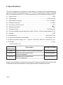
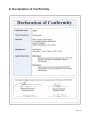
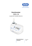
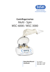
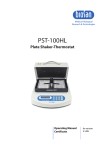
Medical–Biological
Research & Technologies
DEN-1
Densitometer
Suspension turbidity detector
Operating Manual
Certificate
for version
V.1AW
Contents
1. Safety Precautions
2. General Information
3. Getting Started
4. Operation
5. Specifications
6. Maintenance
7. Warranty and Claims
8. Declaration of Conformity
Page 2
1. Safety Precautions
The following symbol means:
Caution: Make sure you have fully read and understood the present Manual
before using the equipment. Please pay special attention to sections marked
by this symbol.
GENERAL SAFETY
·
Use only as specified in the operating manual provided.
·
The unit should be saved from shocks and falling.
·
After transportation or storage keep the unit under room temperature for 2-3hrs
before connecting it to the electric circuit.
·
Use only cleaning and decontamination methods recommended by the
manufacturer.
·
Do not make modifications in design of the unit.
ELECTRICAL SAFETY
·
Connect only to a external power supply unit with voltage corresponding to that
on the serial number label.
·
Use only the external power supply unit provided with this product.
·
Ensure that the power switch and external power supply unit are easily
accessible during use.
·
Disconnect the unit from the external power supply unit before moving.
·
If liquid penetrates into the unit, disconnect it from the external power supply unit
and have it checked by a repair and maintenance technician.
DURING OPERATION
·
Do not operate the unit in environments with aggressive or explosive chemical
mixtures.
·
Do not operate the unit if it is faulty or has been installed incorrectly.
·
Do not use outside laboratory rooms.
The Select and Install buttons are used only for calibration of the unit
according to p. 3.4. Do not press the buttons in other cases, as this can cause
calibration reset and recalibration will be needed.
BIOLOGICAL SAFETY
·
It is the user's responsibility to carry out appropriate decontamination if
hazardous material is spilt on or penetrates into the equipment.
Page 3
2. General Information
DEN-1 densitometer has been designed for solution turbidity measurement in the
range of 0.3 - 5.0 McFarland units (100x106 - 1500x106 cells/ml). DEN-1 is capable of
measuring solution turbidity in a wider range (5.0 - 15.0 McFarland units) however, it is
necessary to remember that in this case the standard deviation values increase.
DEN-1 densitometer is used for determining concentration of cells (bacterial, yeast
cells) in the fermentation process, for detection of susceptibility of microorganisms
against antibiotics, for identification of microorganisms with various test systems, for
measuring optical density at fixed wavelength and for quantitative evaluation of soluted
substance concentration.
The operation principle is based on optical density measurement with digital
presentation of the results in McFarland units.
The unit is calibrated at the factory and saves calibration data when being switched
off. However, in can be calibrated by 2-6 points in 0.5 - 5.0 McFarland unit range if
necessary. Both commercial standards (e.g. produced by bioMerieux, Lachema, etc.)
and the standards prepared in the laboratory can be used for calibration. Table 1 shows
the data provided by the McFarland standard manufacturer bioMerieux.
Table 1. Interpretation of McFarland Standard results into corresponding numeric values of bacterial suspension concentration and their optical density at 550 nm.
McFarland
Standard
0.5
1
2
3
4
5
Composition
Concentration
BaSO4
2.40x10⁻⁵ mol/l
4.80x10⁻⁵ mol/l
9.60x10⁻⁵ mol/l
1.44x10⁻⁴ mol/l
1.92x10⁻⁴ mol/l
2.40x10⁻⁴ mol/l
Interpretation
Bacterial
Theoretical optical
concentration*
density at 550 nm**
150x106 cells/ml
0.125
300x106 cells/ml
0.25
600x106 cells/ml
0.50
0.75
900x106 cells/ml
1.00
1200x106 cells/ml
1.25
1500x106 cells/ml
* Bacterial concentration depends on microorganism size. The numbers represent
an average value valid for bacteria. For yeasts, which are larger in size, these
numbers should be divided by about 30.
** Values correspond to optical densities of bacterial suspensions. The BaSO4
solutions optical density values differ, because the particle size and form differ from
those of bacteria and light is diffracted differently.
Page 4
3. Getting started
3.1. Unpacking
Remove packing materials carefully and retain them for future shipment or
storage of the unit.
Examine the unit carefully for any damage incurred during transit. The warranty
does not cover in-transit damage.
3.2. Complete set. Package contents:
Standard set
DEN-1 Densitometer suspension turbidity detector................................1 pce.
external power supply unit ....................................................................1 pce.
Operating Manual, Certificate ...............................................................1 copy
Optional accessories
A-16 adapter for tubes.....................................................................on request
CKG16 calibration kit for glass tubes 16 mm in diameter ..................on request
CKG18 calibration kit for glass tubes 18 mm in diameter ..................on request
3.3. Set up:
Plug the external power supply unit into the 12 V socket at the rear side of the
unit (fig.1/2).
Place the unit on the horizontal even working surface;
1
2
3 4
Power
DC-12
Calibration
select
install
Fig.1 Rear panel
3.4. Calibration
The device is pre-calibrated at the factory for operation with the glass tubes 18 or 16
mm in external diameter (see the label on the bottom side of the unit) at temperature
range from +15°C to +25°C and saves calibration data when being switched off.
Note! For work with other type tubes (e.g. with different outer diameter, bottom
shape or different material, e.g. transparent plastic tubes) it is necessary to
perform calibration in the specified tubes.
Perform calibration in the following sequence from the lower calibration value to the
higher values: 0.5, 1.0, 2.0, 3.0, 4.0, and 5.0. Use at least 2 points for calibration.
Page 5
To perform calibration:
3.4.1. Switch ON (position I) the unit with the Power switch (Fig.1/1) on the rear panel.
3.4.2. Press the Select button (fig.1/3) on the rear panel (use a thin pin of maximum
diameter 2 mm for pressing the Select and Install buttons). A flashing "0.5"
indication will be shown on the display, showing that the unit is ready to save
calibrations value of the first point 0.5 McF.
Note! Shake the tube with the standard solution, if necessary (it is recommended to use vortex, e.g. Personal Vortex V-1 plus, for shaking).
3.4.3. Insert the tube with the standard solution, corresponding to the calibration point
value, into the socket of Densitometer (fig.2/1).
3.4.4. Press the Install button using a pin (fig.1/4). First point “0.5” will be saved in the
unit memory and the next calibration value will be displayed (flashing 1.0
indication will be displayed).
Note! It is recommended to calibrate as many points as possible to obtain
precise results. The minimum requirement is to calibrate 2 points
closest to the working range limits (e.g. 0.5 and 5.0 for operation in 0.5 5.0 McF unit range).
3.4.5. Repeat steps 3.4.3 - 3.4.4 until the calibration is completed (1-5 times, i.e. as
many times as many points the chosen calibration curve has).
3.4.6. If a standard is not available, press the Select button for the next calibration
value to be displayed.
3.4.7. After installing the last standard value “5.0” or skipping it (the Select button),
the unit exit the calibration mode automatically. The unit is ready for operation.
Note! If pressing the Install button during the calibration process does not
cause switching to the next standard value, it means that the currently
inserted in the densitometer socket Standard has lower turbidity value
than the previous standard. The reason is that the inserted standard
solution turbidity does not correspond to the required value (the standard
is to be shaken or replaced).
3.4.8. After finishing the calibration switch OFF the unit using the Power switch
(position O). Disconnect the external power supply unit from electric circuit.
Page 6
4. Operation
Recommendation during operation
·
Keeping the unit switched on for 15 min before starting the operation for the
operation mode stabilisation is recommended.
·
If flat-bottomed tubes are used, the solution level should be higher than 7 mm from a
tube bottom; if round-bottomed tubes are used, the level should be higher than 12
mm from a tube bottom.
4.1. Connect the external power supply unit to electric circuit.
4.2. Switch ON the unit using the Power switch (Fig.1/1) on the rear panel (position I).
4.3. The following indication may be shown on the display (fig.2/2):
“0.0” means that the unit is calibrated and ready for operation (if no any tube
inserted);
“CC” (flashing) means that the unit is not calibrated. Calibrate the unit.
“EE” means that operator error message. Switch OFF the unit and then switch ON
again.
4.4. Shake the tube with the solution (it is recommended to use vortex, e.g. Personal
vortex V-1 plus, for shaking) and insert it into the socket (fig.2/1). The McFarland
value for the solution will be shown on the display (fig.2/2).
4.5. Glass and transparent plastic tubes (16 or 18 mm in external diameter) can be
used for work with DEN-1 densitometer. An adapter must be used for work with
tubes which are 16 mm in external diameter.
Note! The unit must be calibrated each time a tube type (e.g. with different outer
diameter, bottom shape or different material [transparent plastic tubes]) is
changed.
4.6. After finishing the operation switch OFF the unit using the Power switch (position
O). Disconnect the power supply from electric circuit.
1
2
Fig.2 Front panel
Page 7
5. Specifications
The unit is designed for operation in cold rooms, incubators and closed laboratory
rooms at ambient temperature from +4?C to +40?C and maximum relative humidity
80% for temperatures up to 31°C decreasing linearly to 50% relative humidity at 40°C.
5.1. Light source ................................................................................................LED
5.2. Wavelength ................................................................................ë = 565 ±15 nm
5.3. McFarland unit range ..................................................................0.3 - 15.0 McF
5.4. Display resolution..................................................................................0.1 McF
5.5. Accuracy, of the full scale ...........................................................................+ 3%
5.6. Measurement time ....................................................................................1 sec
5.7. Sample volume ............................................................................2 ml minimum
5.8. Recommended external diameter of tube 18 mm or 16 mm (using adapter A-16)
5.9. Display .......................................................................................................LED
5.10. Dimensions ...........................................................................165x115x75 mm
5.11. Input current/power consumption............................................12 V, 80 mA / 1 W
5.12. External power supply unit .... input AC 100-240 V 50/60 Hz, output DC 12 V
5.13. Weight* ...................................................................................................0.7 kg
* Accurate within ±10%.
Optional
accessories
A-16
CKG16
CKG18
Description
Catalogue number
Adaptor for tubes 16 mm in external diameter
BS-050102-AK
Calibration kit for glass tubes
16 mm in diameter
Calibration kit for glass tubes
18 mm in diameter
BS-050102-BK
BS-050102-CK
Biosan is committed to a continuous programe of improvement and reserves the right
to alter design and specifications of the equipment without additional notice.
Page 8
6. Maintenance
6.1. If the unit requires maintenance, disconnect the unit from the electric circuit and
contact Biosan or your local Biosan representative.
6.2. All maintenance and repair operations must be performed only by qualified and
specially trained personnel.
6.3. Standard ethanol (75%) or other cleaning agents recommended for cleaning of
laboratory equipment can be used for cleaning and decontamination of the unit.
Page 9
7. Warranty and Claims
7.1. The Manufacturer guarantees the compliance of the unit with the requirements of
Specifications, provided the Customer follows the operation, storage and
transportation instructions.
7.2. The warranted service life of the unit from the date of its delivery to the Customer
is 24 months. Contact your local distributor to check availability of extended
warranty.
7.3. If any manufacturing defects are discovered by the Customer, an unsatisfactory
equipment claim shall be compiled, certified and sent to the local distributor
address. Please visit www.biosan.lv, Technical support section to obtain the claim
form.
7.4. The following information will be required in the event that warranty or postwarranty service comes necessary. Complete the table below and retain for your
records.
Model
Serial number
Date of sale
Page 10
DEN-1 Densitometer Suspension turbidity detector
8. Declaration of Conformity
Page 11
Biosan SIA
Ratsupites 7, build. 2, Riga, LV-1067, Latvia
Phone: +371 6742 6137
Fax: +371 6742 8101
http://www.biosan.lv
Version 1.04 - October 2013