1
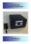
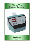
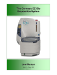
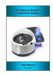
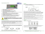
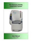
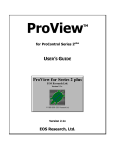
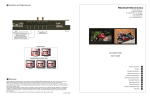
The Genevac
EZ-2 Inert Gas Purge System
User Manual
Issue 1-6 – June 2005
Part Number 04-4219
Genevac EZ-2 Inert Gas Purge System
AMENDMENT CONTROL FORM
Revision
Number.
Issue and Reason for Change
Date Issued
1
Change in hose adapter.
2
Spares items 1b and 1c re-identified
28 October 2003
3
Changes to EU Declaration of Conformity
09 February 2004
4
Introduction of Block Diagram
5
Changes to EU Declaration of Conformity and Addition of EZ-2 Err 42 explanation.
Connection Kit Item 4 – Part Number Change. Item 11 transferred from consumables kit.
Introduction of Disposal and recycling instructions.
6
04 August 2003
20 April 2004
21 September 2004
28 June 2005
Contents
AMENDMENT CONTROL FORM....................................................................................................i
1
Introduction .............................................................................................................................1
1.1 Safety symbols........................................................................................................................1
WARNING...............................................................................................................................1
Caution....................................................................................................................................1
Note ........................................................................................................................................1
1.2 Connection Kit Contents: ........................................................................................................2
1.3 Spares.....................................................................................................................................4
1.4 Installation...............................................................................................................................3
2
Operation ................................................................................................................................6
3
Fault diagnosis........................................................................................................................7
4
Inert purge gases....................................................................................................................7
5
Technical data .........................................................................................................................8
Inert Gas supply......................................................................................................................8
Control Module........................................................................................................................8
Dimensions .............................................................................................................................8
Electrical .................................................................................................................................8
6
EC Declaration of Conformity .................................................................................................9
7
Safety......................................................................................................................................9
8
Useful information.................................................................................................................10
9
Disposal and Recycling ........................................................................................................10
These instructions are subject to change without notice.
No part of these instructions may be reproduced in any form or
be processed, duplicated or distributed by electronic or optical
means without the written permission of Genevac Limited.
All rights reserved. © Genevac Limited
These operating instructions should be read before you use the
Genevac EZ-2 Inert Gas Purge System.
Keep them near the system for easy reference.
04-4219 Issue 1-6 – June 2005
Page i
Genevac EZ-2 Inert Gas Purge System
1
Introduction
The Genevac Inert Gas Purge system is designed to
be fitted to the Genevac EZ-2 & EZ-2plus Personal
Evaporators, with a minimum of interference to
wiring and piping.
The primary function of the Inert Gas Purge system
is to control the supply of inert gas to the evaporating
system during the evaporation of low flash point
solvents, such as diethyl ether, to prevent the
possibility of explosion.
The system is comprised of a:
control module
and
Fig 1 – Inert Gas Purge (IGP)
remote control pad
1.1
Safety symbols
The following safety symbols are used throughout
this manual.
The definitions and scope of each symbol is as
described below.
WARNING
THIS SYMBOL WILL INDICATE HAZARDS THAT
CAN LEAD TO SERIOUS MATERIAL DAMAGE OR
POTENTIAL SERIOUS INJURY.
Caution
Fig 2 – Remote Control
This symbol will give information about hazards
that can be harmful to your health or lead to
material damage.
Note
This symbol will give information about technical
requirements which if not followed, can lead to
malfunctions, inefficiency and reduced productivity.
This symbol indicates that there may be a risk to
sample integrity.
IMPORTANT
THIS SYSTEM MUST BE
EARTHED – SEE PAGE 9
04-4219 Issue 1-6 – June 2005
Page 1 of 10
Genevac EZ-2 Inert Gas Purge System
1.2
Connection Kit Contents:
Description
Hose 3/8 With Connectors (See Breakdown for spares below)
Tube Flex Nylon 4mm OD 2.5 ID
Tube PTFE 6mm OD 4mm ID
Tube PTFE 8mm OD 6mm ID
Knob Long (See Breakdown for spares below)
Knob Short (See Breakdown for spares below)
Fitting Stud 8mm S/S
Connector Straight 4mm – 4mm (usage optional)
Reducer Plug 6mm – 4mm M-F
Reducer Serto 6mm – 8mm F-M
Male Adapter - Union
1
1.3
2
7
8
Spares (available on request):
Description
Hose 3/8 With Connectors
Coupling Plug QR
Fitting 3/8 BSP – ¼ BSP M-F
Washer ¼ x 1 Penny
Washer
Main Supply Fuse 100 - 120V T2A “Siba”
Main Supply Fuse 208 - 230V T1A “Siba”
3
Part Number
70-0790
AB7001
AB7028
AB7006
70-0785
70-0786
04-0936
04-1017
04-1018
04-3982
04-3855
4
9
Quantity
1
2
2
2
1
1
1
1
1
1
1
5
10
Part Number
04-1650
04-0928
04-1651
04-4165
04-3878
04-4217
04-4218
U/m
EA
Metre
Metre
Metre
EA
EA
EA
EA
EA
EA
EA
Fig ID
1
2
3
4
5
6
7
8
9
10
11
6
11
Quantity
1
1
1
2
2
1
1
U/m
EA
EA
EA
EA
EA
EA
EA
Fig ID
1a
1b
1c
56a
56b
N/A
N/A
1a
1b
1c
56a
56b
Visit: http://www.genevac.com/contact/ezspares.html to request all of the above items online.
Page 2 of 10
04-4219 Issue 1-6 – June 2005
Genevac EZ-2 Inert Gas Purge System
1.4
Installation
THE INERT GAS PURGE UNIT (IGP) MUST ONLY
BE FITTED BY AN ENGINEER THAT THE
COMPANY DEEMS TO BE COMPETENT IN
MECHANICAL AND ELECTRICAL INSTALLATION
WORK.
THE EZ-2 EVAPORATOR MUST BE ISOLATED
FROM THE MAINS POWER SUPPLY DURING
INSTALLATION OF THE INERT GAS PURGE.
The Inert Gas Purge system (IGP) can only be fitted
to an EZ-2 evaporation system built with the Inert
Gas Purge option.
A
B
C
The IGP is supplied with a tubing and connection kit
to facilitate connection of the unit to the EZ-2
evaporation system.
Before connecting the pipes to the system
ensure that all pipe ends are cut square.
D
E
F
Purge In: Connect the inert gas supply hose (700790) to the 8 mm push in fitting “A” on the purge
unit to a suitable regulated supply. See ‘Technical
data’ section for gas pressure requirements.
G
Fig 3 - Inert Gas Purge (IGP)
H
I
J
Fume Hood: Connect suitable length of PTFE hose
(04-0937) from the fume hood to connection “G” on
the purge unit.
Filter Drain: Connect suitable length of Nylon Flex
hose (AB7001) to reducer plug (04-1018) and insert
in to the 4 mm push in fitting “E” on the purge unit,
placing the free end of the hose into a suitable waste
container. Only water will be emitted.
EZ-2 Outlet: Connect 1 metre length of PTFE hose
(AB7028) to connection “F” on the purge unit using
reducer 04-3982. Remove blanking plug from EZ-2
Side Panel connection “I” and connect hose.
K
Fig 4 - EZ-2 Side Panel
EZ-2 Inlet: Connect 1 metre length of
(AB7028) to connection “D” on the
Unscrew and remove filter from EZ-2
connection “H” and connect hose using
3855.
PTFE hose
purge unit.
Side Panel
adapter 04-
Remote: Connect the remote control unit to the
‘REMOTE’ socket “B” on the purge unit.
EZ-2 Side Panel connection “J” is not used at
present and has a blanking plug fitted. When using
the Inert Gas Purge System, this blanking plug
should be removed and retained.
04-4219 Issue 1-6 – June 2005
Page 3 of 10
Genevac EZ-2 Inert Gas Purge System
1.4
Installation (Continued)
EZ-2 PANEL CONNECTION “K” HAS A
“BLANKING PLUG” AND SECURITY BRACKET
FITTED WHEN IT LEAVES GENEVAC. THIS MUST
ONLY BE REMOVED BY AN ENGINEER THAT
THE COMPANY DEEMS TO BE COMPETENT IN
MECHANICAL AND ELECTRICAL INSTALLATION
WORK.
REMOVING THE SECURITY BRACKET AND
BLANKING PLUG AND REPLACING IT WITH THE
CONTROL
CABLE
IS
POTENTIALLY
HAZARDOUS SINCE THE CABLE CARRIES
MAINS VOLTAGE.
ALWAYS ENSURE THAT THE EZ-2 IS SWITCHED
OFF AND UPLUGGED FROM THE MAINS POWER
SUPPLY BEFORE ANY WORK COMMENCES.
THE SECURITY BRACKETS MUST BE FITTED TO
EZ-2 END OF THE CABLE BEFORE THE MAINS
POWER SUPPLY IS RESTORED.
Ensure Mains power is isolated and that the power
lead is unplugged from evaporator.
Fig 5 – Blanking Plug and Bracket
Remove bracket securing screws (qty 2) and bracket.
Remove Blanking Plug and retain in a safe place.
(Without the IGP Module, EZ-2 will not work without
this plug being fitted).
Connect control cable to EZ-2 Side Panel connection
“K” (See Fig 4) and refit security bracket and
securing screws (qty 2).
Fig 6 – EZ-2 Control Cable and Bracket
Fig 7 - IGP Control Cable and Bracket
Page 4 of 10
04-4219 Issue 1-6 – June 2005
Genevac EZ-2 Inert Gas Purge System
Fig 8 – Block Diagram
04-4219 Issue 1-6 – June 2005
Page 5 of 10
Genevac EZ-2 Inert Gas Purge System
2
Operation
With the key selector set to NORMAL, the EZ-2 can
be used without the IGP being disconnected and
without an inert gas supply being available.
With the key selector set to PURGE, the purge
function is available.
Ensure that the inert gas supply meets the pressure
requirements as detailed in the ‘Technical data’
section.
Fig 9 – IGP Remote Control
Ensure that the EZ-2 lid is closed and that the
Thumb Screws (qty 2) are fitted, longest to the right
rear position.
Switch on evaporator; note that the ‘POWER’ light,
the ‘RESET’ light and the ‘N2OK’ light will be
illuminated on the purge system remote control unit.
Reset light is only lit when chamber pressure is at
atmospheric.
If ‘N2OK’ lamp is not lit then recheck inert gas supply,
pipes and connections.
Press ‘START’ on EZ-2 control panel, screen will
display ‘not PrGd’.
Press ‘START’ on the remote. The ‘PURGING’ light
will flash whilst the system is being purged.
The purge period is set for 240 seconds (4 Mins).
The green ‘READY’ lamp will be illuminated when
the purge cycle is completed and the system is ready
to start the run.
Fig 10 - Thumb Screws
Press the START button on the EZ-2. If ‘START’
button on EZ-2 control panel is not pressed
immediately, the IGP will wait for 60 mins before
resetting and will continue to purge during this
period.
In exceptional circumstances i.e. very cold chamber,
the EZ-2 could take longer to start the run this may
require a custom run configuration.
Centrifuge Run: The IGP relies on the EZ-2 pulling
a small vacuum to indicate the start of a run, which
this run doesn’t. Please contact Genevac if you
need to operate the EZ-2 on this run setting with
Inert Gas Purge.
The purge cycle can be interrupted at any time
during the purging cycle by pressing the ‘CANCEL’
button.
Fig 11 – EZ-2 Control Panel
Page 6 of 10
If you pause a run or if the ‘N2OK’ light
extinguishes at any time during the purge cycle,
the system will reset and you will have to
perform a complete purge cycle again.
04-4219 Issue 1-6 – June 2005
Genevac EZ-2 Inert Gas Purge System
When the run is complete or is stopped, the system
will automatically vent, using IGP, for 90 seconds
(indicated by Brake Timer in EZ-2 display counting
down to zero).
With inert gas purge unit (IGP) connected to the
EZ-2 and the key selector set to PURGE, ensure
that the gas supply is always available during the
runs.
3
Fault diagnosis
•
•
•
‘N2OK’ not lit: 1.
Check inert gas supply connection.
2.
Check inert gas supply is at the correct
pressure. See ‘Technical data’ section
for pressure.
3.
Check fuse.
Momentary dipping in purge pressure
causes purge to cancel.
1.
Check inert gas supply pressure.
2.
Regulator / filter may need servicing,
contact Genevac Service Department.
Purge system resets a few seconds after
purge cycle started: 1.
•
RESET lamp illuminated: 1.
•
There is an internal fault in the control
module. Contact Genevac Service for
assistance in this case.
Err 42 Displayed on EZ-2: 1.
4
‘CANCEL’ button has been pressed.
Red ‘FAULT’ lamp illuminated: 1.
•
Check that the lid of the EZ-2, is closed
and secured with Thumb Screws (Qty
2).
Inert Gas Purge Unit has been reset or
Gas supply has been lost.
Inert purge gases
The system is suitable for use with either nitrogen or
argon, which should be dry.
Consult Genevac Service if you intend to use an
alternative inert gas.
04-4219 Issue 1-6 – June 2005
Page 7 of 10
Genevac EZ-2 Inert Gas Purge System
5
Technical data
Inert Gas supply
Max pressure
Min pressure
Flow
Purge system filter draining
N2OK Set point
8 bar
3 bar
30 litres/min @ STP
Automatic
0.9 bar
Control Module
Weight
9 Kg
Dimensions
Control Module (W x D x H)
260 x 300 x 180 mm
Electrical
Power supply
208 - 230V ±10%, 50/60Hz, single phase
100 - 120V ±10%, 50/60Hz, single phase
Note: - The purge system is powered from the
EZ-2 connection cable and requires no external
supply.
Fuse ratings
208 - 230V
100 - 120V
T1A “Siba”
T2A “Siba”
Contact Genevac Service or use our web based spares form:
http://www.genevac.com/contact/ezspares.html
to request replacement fuses and other components.
Page 8 of 10
04-4219 Issue 1-6 – June 2005
Genevac EZ-2 Inert Gas Purge System
6
EC Declaration of Conformity
7
Safety
We Genevac Limited
Declare that this product:
Inert Gas Purge System
Complies with the relevant Essential Health and
Safety Requirements of the European Machinery
Directive (89/392/EEC as amended by 91/368 EEC
and 93/44/EEC). The EMC Directive 89/336/EEC
and the Low voltage Directive 73/23/EEC.
Conformity is demonstrated by compliance with the
following specifications: EN 60204-1:1998, Safety of machinery– Electrical
equipment of machines-Pt 1 General Requirements
BS EN ISO 12100 pts 1 & 2:2003, Safety of
Machinery - Basic concepts, general principles for
design.
BS EN 50082-1: 1998, Electromagnetic
compatibility-Generic immunity standard.
BS EN 61010-1: 1993, Safety requirements for
electrical equipment for measurement, control and
laboratory use.
04-4219 Issue 1-6 – June 2005
WARNING!
THIS SYSTEM MUST BE EARTHED
THIS PURGE SYSTEM IS A SAFETY CLASS 1
PRODUCT
ACCORDING
TO
IEC
CLASSIFICATION. IT MUST NEVER BE USED
WITH ANY INTERRUPTION TO THE SAFETY
EARTH CONDUCTOR. IT IS AN INSTALLATION
CATEGORY II PRODUCT AND IS INTENDED TO
OPERATE FROM A NORMAL SINGLE-PHASE
SUPPLY.
THIS PURGE SYSTEM HAS BEEN DESIGNED TO
BE USED IN A POLLUTION DEGREE 1
ENVIRONMENT (NO POLLUTION, OR ONLY DRY
NON-CONDUCTIVE POLLUTION).
ANY MAINTENANCE OR REPAIR OF THIS
PRODUCT SHALL BE CARRIED OUT BY
GENEVAC
PERSONNEL
(OR
APPROVED
REPRESENTATIVES OF GENEVAC) USING ONLY
APPROVED SPARE PARTS
Page 9 of 10
Genevac EZ-2 Inert Gas Purge System
8
Genevac Limited
The Sovereign Centre
Farthing Road
Ipswich
IP1 5AP
United Kingdom
Sales and Service Hotlines
Service Hotline: +44 (0) 1473 243000
Sales Hotline: +44 (0) 1473 240000
Useful information
If you need to contact Genevac for assistance, use
either the telephone or fax Hotlines given.
It will always help Genevac Service if you have the
serial numbers at hand for the components of your
system
If you need to contact Genevac Sales for information
on Service Contracts or products, use the telephone
or fax Hotlines given.
Alternatively, Email or visit our web site.
9
Disposal and Recycling
Fax: +44 (0) 1473 461176
Email: [email protected]
Web site: http://www.genevac.com
Genevac Inc
707 Executive Boulevard
Suite D
Valley Cottage
New York
10989
United States of America
The Genevac product should not be discarded in
your regular disposal stream. Contact your
Distributor or Genevac for proper disposal
instructions.
Within the EU, it is Genevac’s responsibility under
the WEEE directive to provide for the recycling of
their products.
Sales and Service Hotline
(1) 845 267 2211
Fax (1) 845 267 2212
Email: [email protected]
Page 10 of 10
04-4219 Issue 1-6 – June 2005