1
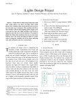
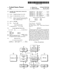
Mid-Year Report
1
iLights Senior Design Project
Jose D. Figueroa, Matthew C. Ryder, Nicholas Wittemen, and Chris Merola, Team Soules
Abstract— People listen to music using iTunes more than any
other media player currently available. Most media players have
visualizers that can be placed on the screen to give the music more
excitement. There problem with this is that visualizer software
limits lighting effects simply to the screen and no where else.
Light controllers exist, but for a high price and with no easy-touse interface. We propose a plug-in for iTunes that would give the
user an easy-to-use interface that will control incandescent lights
of various colors to bring the visualizer out of the screen and
bring color and excitement to the user’s environment.
I. INTRODUCTION
problem our design solves is the constraint of light
visualizations from iTunes in terms of actually realizing an
external light visualization through the control of
incandescent lights. This solution will provide an appropriate
visual stimulation to complement the audio experience of
iTunes users. Users would like to be able to bring life to their
music and do away with the isolation of the computer screen.
While devices already exist to dim lights in response to music,
they do not give the user a GUI (Graphical User Interface)
from which they can control what audible frequency ranges the
lights will interact with. iLights allows users the ability to plug
in four incandescent lights and have them interact with the beat
of the song playing in real time. Users can select which range
of the audible spectrum they want each channel to react to
through the iTunes plug in; the user will see a display of the
frequency spectrum output of the song to allow band selection
to be done straightforwardly. This will supply the user with
four selectable ranges for four different lights to react in
response to treble, bass, mid-range, or any other variation of
the audible spectrum.
HE
T
A. Requirement Specifications
1. Deliver up to 500W X 4 output channels, 2000W max.
2. Go from off to fully illuminated and back off again in
under 75ms (800bpm).
Manuscript received November 20, 2008. This work was supported in part by
SDP 2009.
Jose D. Figueroa is a senior in Electrical Engineering at UMASS Amherst
Nicholas Wittemen is a senior in Electrical Engineering at UMASS Amherst
Chris Merola is a senior in Electrical Engineering at UMASS Amherst
Matthew C. Ryder is a senior in Electrical Engineering at UMASS Amherst
3. Lights to be fully illuminated within 80ms of audio
input (Human sync detection range).
4. iTunes plug-in that allows users to select frequency
band between 20 - 20,000Hz as trigger for each
channel.
5. USB 1.0 link to Arduino microcontroller.
6. Documented source code + user manual
II. DESIGN
A. System Overview
Our basic system design includes a computer with the iTunes
program and our GUI along with a frequency analyzer. The
software will communicate with our hardware via serial port
communication from a USB 2.0 output on the computer to a
USB 1.0 connection that will tie into the input of the iLights
Hardware Box. The hardware box contains the microcontroller
and electrical circuit components needed to use the frequency
information provided by our GUI to obtain control of the four
channels where the incandescent lights will be connected. Each
channel will be capable of safely handling 500W. Addition
shielding will be included in order to minimize the hazards of
Electromagnetic Interference (EMI) resulting from the power
signals.
Mid-Year Report
2
B. Block Diagram
User Input
Computer
Open GL Interface
iTunes
Frequency
Extraction
C++
Power Source
Arduino
Serial input
buffer
Check for data and read data
Light
Light
Light
Light
Dimming Control
Library, call a *.dll file, which can access frequency data
through iTunes provided variables. iTunes does a FFT (Fast
Fourier Transform) of the audio being played and makes
available the power contained in 256 samples spaced linearly
from 20 Hz to 20kHz. The data is provided is of type Uint8
giving 256 steps of resolution.
OpenGL is used to display this data graphically,
specifically a package named freeglut. We have chosen this
package because is built to be both easy to implement and
extremely portable; although we are developing in Windows
we would like to be able to port our software to OSX. At this
time we are displaying a level bar for each of the 256 available
bands. Our code controls the bar height using a log scale in
order to compare power in the same way as the human ear.
As of now our software is able to communicate with
iTunes, extract the frequency spectrum of the audio being
played, and display this information graphically. The next step
will be to implement a user interface. We will use handlers
available in the freeglut package to do this. We have already
experimented with input using this package and have
determined that it will be able to handle the input our project
requires.
Triac
Triac
Triac
Triac
Fig. 1. System block diagram. Two large boxes encompass the portions
working from the Arduino platform and from the PC.
C. System Specification
iTunes interface
Our software must be able to communicate with iTunes in
order to control lights based on the music being played. The
software will also allow the user to select frequency ranges that
will control each iLights electrical outlet. From data extracted
with iTunes we will determine the power contained in a
number of user selected frequency bands and use this to set the
amplitude of the connected lights. Due to the physical
properties of triacs, the fastest we can adjust the power sent to
our lights is 120 times per second. This is the rate at which we
will retrieve audio spectrum information form iTunes. This
data will be updated and packaged to be sent via USB to our
hardware continuously. As of this time we are able to extract
frequency data from iTunes and display a spectrograph of the
audio file being played.
To extract frequency data we use the software
development kit released by apple for visualization
development. Using this we implement a Dynamic Link
Serial Port Communication Link
The link from the pc to the microcontroller that triggers the
switching circuitry is compromised of 2 parts: C++ code which
translates and transmits the extracted frequency data over the
serial port; and an Arduino prototyping board with an
Atmega168 that has been programmed to read the serial port
data and interpret it into control instructions for triggering the
triac circuits.
The extracted frequency data will consist of 256 samples of
the audible frequency range, and the user will specify 4
different spans of this frequency band they want their 4 lights
to react to. The power over each of these frequency bands will
provide the output control signal to be written to the serial
port. To send these 4 signals simultaneously we will have to
store them in an array and write the whole array to the serial
port. This writing must occur at the same rate we set the
Arduino board to operate at. Currently a baud rate of 19200
has been used consistently in our code. The microcontroller
will then read the serial port and take the 4 individual elements
of this array and translate the power over each frequency band
into the appropriate phase control.
Phase control works by turning on a fraction of each half
wave; current through the load is proportional to the area under
this portion of the sine wave. The Arduino determines when to
trigger each triac and turn on this signal to provide phase
control. This is done using the Arduino to detect zerocrossings which, since our ac power is mostly constant at
Mid-Year Report
120Hz, will remain at approximately 1/120 seconds apart. This
data will continuously be collected, allowing us to accurately
switch on during the desired phase of the pulse, resulting in
real-time phase control of the 4 incandescent lights.
Light Control Circuitry
The idea for controlling the light is to use a type of phase
control. AC mains are rated at 120VAC at 60Hz. The amount
of power provided to an incandescent light is essentially the
area under the sinusoidal wave. If we are able to supply half
the amount of power during every half-cycle then we
essentially deliver half the power to the incandescent bulb
which in return creates an affect of the incandescent light bulb
being half as bright as usual. The use of a power triac is ideal
for this. This is demonstrated in the figure below:
Fig. 2. Graph of AC mains (RED) and supply of half of each half-cycle to
the load (GREEN). Graph also represents triggering the triac on to dim
the bulb at half of its full brightness (GREEN).
The power triac is a device of the Thrysistor family which
allows for switching of AC loads either resistive or inductive.
The triac of choice is the BTA20-700CW snubberless triac
from ST Microelectronics. The way the device works is by
attaching the mains (120VAC) to pins A1 and A2. Pin G is a
gate triggering pin which will activate the triac and allow
current to flow through pins A2 and A1. The uniqueness of this
device is its capability to block the current flow when the AC
main voltage crosses zero. In order to allow currently flow the
triac would need to be triggered once again. This property
makes the device ideal for phase control of our lights. The triac
is capable of withstanding 700V at 20 A which makes it
completely capable of meeting our design requirements of
500W x 4.
The second device needed to control the lights and interface
with the microcontroller is a Triac Driver IC. This device is
needed to isolate the sensitive microcontroller from the main
lines that the power triac will be controlling. The device of
interest is the FOD4218 newly designed by FAIRCHILD
Semiconductors. This device is a random phase opto-isolated
triac driver. Within the device there is an infrared light
emitting diode which optically triggers an infrared sensitive
triac. When this triac is triggered it will supply an output
3
trigger for the power triac therefore safely preventing any
current from entering the microcontroller.
Fig. 3. Basic structure of design concept for controlling a single
incandescent light bulb or channel. Image provided by Fairchild
Semiconductors
The last major component of the light control circuitry is a
zero cross detection circuit. This is needed in our design so
that the system knows when the AC mains cross zero and
therefore calculate a delay after the zero crossing to switch the
power triac to its on state. This has been achieved easily with
the use of an Atmega168. Atmel released a bulletin that the
Atmega can be directly connected to the mains with 1Meg
resistors at the input pins and due to the internal clamping
diodes it was possible to achieve a zero cross detection
circuit. The clamping diodes keep the input pins between Vcc
+ 0.5V and Vg – 0.5V. The 1Meg resistors limit the current
1mA max up to 1000V. This will allow us to know when the
main crosses zero in order to set-up a delay trigger to the
power triac. With this trigger to the power triac we can control
where we trigger the power triac on within the half cycle. This,
in return, gives us the ability to control the power to the
incandescent light bulb and vary its brightness with the
microcontroller.
Both triacs in our design are snubberless meaning that there
is no need for external components such as RC or RLC circuits
to suppress transient spikes from the mains or the load. Our
load is also purely resistive so that also eliminated the need of
such circuitry.
Electromagnetic Interference and Compatibility
Since our project involves switching large amounts of AC
current very quickly, electromagnetic interference (EMI) is an
issue we are going to have to address. When large amounts of
current are switched in close proximity to other circuits, they
can induce a current in those circuits which will have a
detrimental effect on performance. For example, in our circuit
we are counting zero-crossings of the main AC line and also
triggering the triacs with digital circuitry. The EM fields
produced by the triac output lines could induce a current in the
zero-cross circuit and produce a fake zero crossing or it could
induce a current in the triac triggering circuit and trigger the
triac when it is not supposed to be triggered. The Federal
Communications Commission (FCC) has passed many
Mid-Year Report
restrictions on the amount of EMI consumer electronics are
allowed to produce. A product which produces too much EMI
will degrade the performance of other products/appliances
nearby.
To help reduce EMI in our circuit, we are going to first use
capacitors to couple the ac lines with the ground lines. This
will prevent sharp and sudden voltage spikes due to ground
noise. Y-type capacitors are ideal for this because they are
double insulated and designed for this purpose. X-type
capacitors can be used between ac line and neutral together to
further reduce interference. We will also arrange our circuit in
such a way that minimizes EMI. The best way to do this is to
have small loops on the PCB and to have lines carrying large
amounts of current going in opposite directions. When two
lines with equal current go in opposite directions, they each
produce an EM field equal but opposite to the other. This will
dramatically reduce our emissions. Large loops in a path
amplify the ability of that path to conduct and radiate noise.
Prevention of this type of noise will be done by keeping highcurrent loops far away from low-current loops and by keeping
loops as small as possible.
D. Design Alternative
We have considered other alternatives in the case that
something may not work as originally planned. Reasons we
would need alternatives would be if iTunes SDK is inadequate
for allowing frequency extraction. In this case we have
considered the possibility of using alternative media players
such as Winamp open-source or VLC media player.
The second design alternative would be replacing the triac if
it is found not to be the best way for controlling the lights.
Silicon-controlled rectifier (SCR) could be another solution for
better switching and control of lights. We could also choose
Resistive Dimming by rectifying AC to DC and using different
lights. However this could limit the amount of power we would
be able to switch due to heat emission.
4
software compatible for both Mac and PC operating systems.
Nicholas Wittemen has been progressively developing a
serial communications link with C++ and the processing
language to make data transfer possible between the iTunes
software plug-in and the Arduino microcontroller that will
drive the triggers for the triacs in order to control the lights
appropriately. He is also the team coordinator.
Jose D. Figueroa has been assigned to designing the triac
circuit which will handle 4 x 500W, 2000W total, and taking
all safety precautions when interfacing with a live AC source.
He is also the webmaster who is responsible for updating and
maintaining Teams Soules’ website.
Matthew C. Ryder as been doing research on EMI
(Electromagnetic Interference) so that our product not only
functions properly within its contained environment but that it
also meets all FCC regulations and safely interfaces with
normal consumer electronics in a home with out effecting or
causing damage to other products.
V. SUMMARY AND CONCLUSIONS
A. System Overview
Please check with your editor on whether to submit your
manuscript as hard copy or electronically for review.
References
B. System Overview
Please check with your editor on whether to submit your
manuscript as hard copy or electronically for review.
ACKNOWLEDGMENT
Team iLights would like to extend our thanks to professor T.
Baird Soules for his guidance and the insight he contributed to
our research.
We would also like to thank Paul Badger, owner of
ModernDevice.com, for his timely and considerate assistance
for handling our requests for assistance.
III. MDR PROTOTYPE IMPLEMENTATION
A. System Overview
Please check with your editor on whether to submit your
manuscript as hard copy or electronically for review
REFERENCES
[1]
[2]
[3]
[4]
IV. PROJECT MANAGEMENT
[5]
A. System Overview
Our team as split the project up into four main areas:
Chris Merola is responsible for designing the easy-to-use
GUI along with the iTunes plug-in with iTunes SDK to extract
frequency information. He is also charged with making the
[6]
[7]
[8]
Shreiner, Dave, Mason Woo, and Jackie Neider. OpenGL Programming
Guide : The Official Guide to Learning OpenGL, Version 2. New York:
Addison Wesley Professional, 2005.
"The World Famous Index of Arduino & Freeduino Knowledge."
<http://www.freeduino.org/>.
"Arduino Home." <http://www.arduino.cc/>.
Curcio, Igor D., and Miikka Lundan. Human Perception of Lip
Synchronization in Mobile Environment. Tech.No. Research Center,
Nokia Corporation. IEEE Xplore, 2007. 1-7.
Benhard, Ryan G. "EMI Considerations in Selecting AC/DC Switching
Power Supplies." Power Supplies. Oct.-Nov. 2005. Elpac Electronics,
Inc. 3 Dec. 2008
<http://www.devicelink.com/mem/archive/05/10/007.html>.
Fairchild Semiconductors: Datasheet: FOD410, FOD4108, FOD4116,
FOD4118 Rev. 1.1.4
Fairchild Semiconductors: Datasheet: Application Note AN-3004
ST Microelectronics: Datasheet: BTA20 BW/CW