1
PHOTOVOLTAIC DISPLAY MODULE
PVDM6
INSTALLATION INSTRUCTIONS
DEALER CONFIGURATION
1.
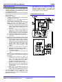
To configure the PVDM6 to display only 4 of the 6 or back
to 6 display readouts, perform the following steps:
2.
3.
4.
5.
6.
7.
8.
Complete the installation and test the operation of the
PVCM40D charge control module.
Before mounting the PVDM6, plug in the network cable to
the PVCM40D charge controller and verify that all the
readings work properly. Calibrate the battery voltage
reading by first measuring the battery voltage with an
accurate digital voltmeter. Adjust the PVDM6 battery
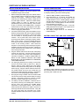
voltage reading to match by adjusting the (P1)
potentiometer (1/4 to one turn maximum), next to the RJ45 jack, on the back of the PVDM6 module. Unplug the
network cable on both ends. (See diagram to the right.)
Determine the mounting method to be used, surfacecutout or single gang electrical box.
For surface-cutout mounting, place the template over the
desired mounting location and mark through the template
the two mounting screw locations. Drill two pilot holes
into the cabinet or mounting surface at the marked
locations. Use a power drill to drive screws into the
mounting surface before mounting the display module.
Back out the screws, cut-out the template leaving the
mounting screw tabs and attach the template with the
screws to the mounting surface. Draw around the
template on the mounting surface marking through the
template around the mounting screw tabs. Carefully cut
out the marked area using a saber saw or router leaving
the mounting screw tabs.
Plug the network cable into the RJ-45 jack, after pulling
it through the cutout hole. Insert the screws through the
front of the module and into the holes and tighten by
hand with a screwdriver. USING A POWER DRILL TO
DRIVE IN THE SCREWS THROUGH THE PVDM6
MODULE WILL VOID THE WARRANTY BY DAMAGING
THE PVDM6 MODULE!!!!
For single gang electrical box mounting, mount the box
securely and install conduit (at least 3/4 in. EMT) as
desired. Route or pull the display end of the network
cable into the electrical box being careful not to damage
the RJ-45 plug. Plug the network cable into the back of
the PVDM6 module and mount the module with 6-32
screws into the tabs of the single gang box. Hand tighten
the screws to avoid damaging the PVDM6 module.
Now plug the charge controller end of the network cable
into its RJ-45 jack and verify that the display is working
properly. Use grease or silicone to cover the controller
side of the network cable plug to avoid corrosion.
For Battery Load Shunt installation, install the shunt in
the positive power leg of the battery bank. Make sure
that the shunt size matches the PVDM6 display
requirement of 500 Amp/50 millivolt. Now connect at
least #18 AWG wire between the spade connectors on
the charge controller and the shunt terminals. Verify that
the shunt signal wires are connected to the correct
terminals otherwise reverse the wires for a proper current
reading.
1.
2.
3.
4.
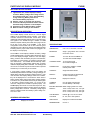
BATTERY ADJUST POT. AND JACK LOCATIONS
The Battery voltage calibration potentiometer is located in
the lower left hand corner of the PVDM6 below the RJ-45
jack, along with a cable error LED.
ATKINSON ELECTRONICS, INC.
Web Site: www.atkinsonelectronics.com
Advance display to Battery Load Percentage.
Hold select button for 15 seconds, the PVDM6 will
switch from its present to the other mode. If the
PVDM6 module is now in “6 reading display” the first
and sixth LED’s will flash for 3 seconds. If the PVDM6
module is now in “4 reading display” the first and fourth
LED’s will flash for 3 seconds.
If you wish to change modes repeat step 2. This mode
setting will remain until changed. Loss of power or low
battery will not change this setting.
This display change function is not available on
PVDM4 displays.
REV 1/03
Distributed by: