1
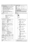
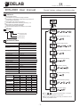
Display
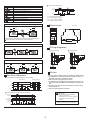
Asymmetry monitoring
Description
L1-L2 phase, change phase by pressing the key
Asy%
Hysteresis
0%
Indication for normal state, flashes when start/reset delay actived
Indication for faults, the output relay is off
Indication for menu setting
11
Indication for overvoltage fault or overvoltage parameter setting
Indication for undervoltage fault or undervoltage parameter setting
14
Ta
Tr
<Ta
12
Tr: Start/reset time delay
To: overvoltage time delay
Tu: undervoltage time delay
Ta: asymmetry time delay
Indication for phase sequence fault or phase sequence parameter setting
Indication for phase failure fault
Indication for asymmetry fault or asymmetry parameter setting
Test
Dimensions
Press key T /R for 0.5s to test the relay
12
11
11
14
Unit: mm
36
12
14
L2
L3
66.5max
L1
MD
T/R
the pressing of the key can work only with normal supply.
When testing, other keys will not be available.
35.5
14
11
12
90
Three phase voltage readable
Press key MD to read the three phase voltage
Wiring diagrams
3phase 3wire
3phase 4wire
U> setting ( take 450V for example)
12
11
12
11
14
12
11
14
14
Notice
Function diagrams
1. The relay should be installed ,operated and maintained by qualified personnel.
2. Don’t disassemble or repair the product whether it operates normally, or no
responsibility is assumed by manufacturer and seller.
3. Please refer to the wiring diagram when connection.
4. Don’t assemble input wire together with strong electric wire in the same pipe.
If necessary, please use shielded wire to avoid affecting the operation of the
relay.
5. Don’t use the relay at the site which can be invaded by corrode gas, strong
sunshine light and rain
6. There is 12 months guarantee on the product.
Phase failure and phase sequence monitoring
Phase sequence
phase failure
L1
L2
L1
L3
L1
L3
L2
L2
L2
L1
L3
L3
11
Tr
14
Tr
Tr
LOAD
LOAD
Tr
12
Overvoltage and undervoltage monitoring
Warning
- Turn power off before installing,
Threshold U>
Hysteresis
wiring or maintaining
- Confirm that power supply voltage is
compatible with rated control
voltage
Hysteresis
Threshold U<
L1/L2/L3
L1/L2/L3-N
14
11
12
Tr
To
Tr
Tu
Tr
<Tu
Fail to follow these instruction will
result in serious injury or fire disaster
<To
-2-