1
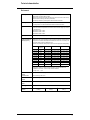
Altivar 68
Telemecanique
Variable speed controllers for asynchronous motors
User’s manual
75 … 630 kW
400 … 500 V
ATTENTION
IT NEUTRAL POINT CONNECTION : In the event of use on a 3-phase plus neutral network with an isolated or high-impedance
system (IT), radio interference suppression filters must not be fitted, use of an earth fault detection kit is required : see Options.
When the speed controller is powered up, the power components and some of the control components are connected to the
line supply. It is extremely dangerous to touch them. The speed controller cover must be kept closed.
After switching the power to the ALTIVAR off, wait for at least 5 minutes before working on the equipment. This is the time
required for the capacitors to discharge. In any case, voltage measurement on terminals + and – is required.
Voltage must be less than 60 V DC.
As a rule, the speed controller power supply must be switched-off before any operation on either electrical or mechanical parts
of the installation or machine.
ATTENTION
The motor can be stopped during operation by inhibiting start commands or the speed reference while the speed controller
remains powered up. If personnel safety requires prevention of sudden restarts, this electronic locking system is not
sufficient : install a device to interrupt the supply on the power circuit and any mechanical brakes.
The speed controller can start automatically by configuration after switching on its power section. You must ensure that no
persons or equipment are endangered.
The speed controller is fitted with safety devices which, in the event of a fault, can shut down the speed controller and
consequently the motor. The motor itself may be stopped by a mechanical blockage. Finally, voltage variations, especially line
supply failures, can also cause shutdowns. If the cause of the shutdown disappears, there is a risk of restarting which may
endanger certain machines or installations, especially those which must conform to safety regulations. In this case the user
must take precautions against the possibility of restarts, in particular by using a low speed detector to interrupt the power to
the speed controller if the motor is subject to an unprogrammed shutdown.
F
R
A
N
Ç
A
I
S
Fault management can be carried out by the speed controller in various ways. Consult chapter E of the programming guide.
The design of equipment must conform to the requirements of IEC standards.
NOTE
When supply of the speed controller is not by the power circuit (L1, L2, L3) but by the 24 volt auxiliary supply, the speed,
temperature and output voltage information shown on the display is not available.
The products and equipment described in this document may be changed or modified at any time, either from a technical point
of view or in the way they are operated. Their description can in no way be considered contractual.
Warning
The Altivar 68 must be considered as a component: it is neither a machine nor a device ready for use in accordance with European
directives (machinery directive and electromagnetic compatibility directive). It is the responsibility of the end user to ensure that the
machine meets these directives.
The speed controller must be installed and set up conforming to the user manual and in accordance with both international and national
standards. Bringing the device into conformity is the responsibility of the systems integrator who must observe, among others, the EMC
and LV directives in its place of use within the European Community.
The specifications contained in this document must be applied in order to comply with the essential requirements of the EMC directive.
2
Contents
Preliminary recommendations / Speed controller - motor connection ___________________________________________________4
Speed controller - motor connection _______________________________________________________________________________5
Available torque ________________________________________________________________________________________________6
Technical characteristics ________________________________________________________________________________________7
Dimensions and fixing___________________________________________________________________________________________9
Mounting recommendations _____________________________________________________________________________________11
ATV-68 enclosure mounting _____________________________________________________________________________________13
Access to terminals ____________________________________________________________________________________________14
Wiring diagrams for control terminals _____________________________________________________________________________16
Wiring diagrams: encoder feedback and RS232 link card terminals ____________________________________________________20
Control terminal block characteristics_____________________________________________________________________________21
Power part wiring diagram ______________________________________________________________________________________24
DC bus power connection diagrams ______________________________________________________________________________27
DC bus connection cable sections and fuses_______________________________________________________________________29
Line cables and fuses __________________________________________________________________________________________30
Special uses / IT network _______________________________________________________________________________________31
Installation and maintenance ____________________________________________________________________________________32
Options ______________________________________________________________________________________________________33
3
Preliminary recommendations / Speed controller - motor connection
Acceptance
Ensure that the speed controller reference printed on the label is the same as that on the delivery note corresponding to the purchase order.
Remove the Altivar 68 from its packaging and check that it has not been damaged in transit.
Handling and storage
To ensure that the speed controller is protected before installation, handle and store the equipment in its packaging.
The ATV-68 range includes 4 speed controller sizes of different weights and dimensions.
Speed controllers are fitted with lifting eyes for easy lifting.
Speed controller - motor connection
Motor power
Currents of high power motors are not standardised and the rating of the speed controller associated with motor power is given as a guide only. It
is necessary to verify that the rated current of the motor used is compatible with the maximum rated output current of the speed controller.
Line current
The line current stated is with the additional line chokes. Theses values are indicative as they depend on line impedance. They are calculated from
the maximum rated current of the speed controller.
Electrical supply and use of line choke
Line chokes are mandatory, except for ratings ATV-68C10N4 to C33N4, if the impedance of line or transformer is higher than:
• 245 µH for rating C10 N4,
• 120 µH for ratings C13, C15 and C19 N4,
• 60 µH for ratings C23, C28 and C33 N4.
In the case where speed controllers are directly interconnected on their power inputs L1, L2, L3 or with very close connections, wiring of additional
line chokes is mandatory.
Very close
Transformer
IL
ATV-68
M
ATV-68
M
ATV-68
M
IL
IL
ATV-68FCi i N4: flux vector speed controllers with sensors
ATV-68FCiiN4 controllers are standard controllers equipped with a factory-fitted and wired encoder feedback card. Only their torque
characteristics are different. Their reference is completed by the letter F (eg. ATV-68F C10N4).
4
Speed controller - motor connection
High torque applications (150% of rated torque available in transient operation), for
75 kW to 500 kW motors
Supply voltage: 400 V -15%…500 V +10% 50 Hz ±5% 60 Hz ±5%
Mains
Motor
Power rating
on motor
plate (1)
500 V
440 V
400 V
460 V
Altivar 68
Line current (2)
400 V
440 V
460 V
Maximum rated current
500 V
400 V
440 V
460 V
Maximum
transient
current (3)
Power
dissipated
at rated
load (5)
References
(7)
500 V
kW
HP
A
A
A
A
A
A
A
A
A
W
75
100
133
121
116
106
142
129
124
113
213
2050
ATV-68C10N4
90
125
161
146
146
129
172
156
156
137
258
2400
ATV-68C13N4
110
150
194
177
169
157
208
189
180
167
312
2800
ATV-68C15N4
132
200
234
224
225
188
250
240
240
200
375
3250
ATV-68C19N4
160
250
304
282
283
244
325
302
302
260
488
4000
ATV-68C23N4
200
300
378
343
338
304
404
367
361
323
606
5000
ATV-68C28N4
250
350
444
403
388
357
475
431
414
380
713
6200
ATV-68C33N4
315
500
577
552
553
464
617
590
590
494
926
7800
ATV-68C43N4
400
600
717
673
675
577
767
720
720
614
1151
9700
ATV-68C53N4
500
800
845
785
787
680
904
840
840
723
1356
12000
ATV-68C63N4
Standard torque applications (variable torque applications,
120% of rated torque in transient operation), for 90 kW to 630 kW motors
Supply voltage: 400 V -15%…500 V +10% 50 Hz ±5% 60 Hz ±5%
Mains
Motor
Power rating
on motor
plate (1)
500 V
440 V
400 V
460 V
Altivar 68
Line current (2)
400 V
440 V
460 V
(6)
Maximum rated current
500 V
400 V
440 V
460 V
(6)
Maximum
transient
current (4)
Power
dissipated
at rated
load (5)
References
(7)
500 V
kW
HP
A
A
A
A
A
A
A
A
A
W
90
100
159
145
116
128
170
155
124
136
213
2400
ATV-68C10N4
110
125
193
175
146
155
206
187
156
165
258
2800
ATV-68C13N4
132
150
234
212
169
188
250
227
180
200
312
3250
ATV-68C15N4
160
200
280
269
225
226
300
288
240
240
375
3800
ATV-68C19N4
200
250
365
338
283
293
390
362
302
312
488
4700
ATV-68C23N4
250
300
453
411
338
365
485
440
361
388
606
5800
ATV-68C28N4
315
350
533
483
388
429
570
517
414
456
713
7300
ATV-68C33N4
400
500
692
662
553
556
740
708
590
592
926
9100
ATV-68C43N4
500
600
860
808
675
692
920
864
720
736
1151
11300
ATV-68C53N4
630
800
1015
942
787
816
1085
1008
840
868
1356
14000
ATV-68C63N4
(1)
Power values given for a switching frequency of 2.5 kHz in steady state. For switching frequencies of 5 and 10 kHz, refer to table on page 7.
(2)
Typical current values, given with additional line choke for rated voltage and for maximum rated current.
400 V… 500V, the presumed short circuit current is 22000 A.
(3)
Transient current for 60 seconds every 10 minutes for voltage 400 V (corresponding to 1.5 times the maximum rated current).
(4)
Transient current for 60 seconds every 10 minutes for voltage 400 V (corresponding to 1.2 times the maximum rated current).
(5)
Power dissipated at maximum rated current and switching frequency of 2.5 kHz.
(6)
In 460 V, only high torque is available.
(7)
Characteristics identical for the ATV-66FCiiN4.
5
Available torque
Continuous operation
For self-cooled motors, cooling is linked to motor speed. Derating therefore occurs at speeds less than the rated speed. Before adjustment of the
integrated thermal protection, it is advisable to consult the motor thermal constant values issued by the motor manufacturer.
Transient operation
The overtorque depends on the maximum transient current of the speed controller.
At startup, the maximum limiting torque is programmable as a function of the speed to up to 1.8 times rated torque.
Overspeed operation
Above rated motor speed, voltage being unable to increase with frequency, there is a reduction in motor induction which results in torque loss.
Warning: consult the motor manufacturer on the mechanical consequences of motor overspeed operation.
High torque applications: torque characteristics
ATV-68CiiN4
C / Cn
(1) Self-cooled motor = steady usable torque
(adjustable internal protection).
1,8 max
(4)
1,5
(2) Force-cooled motor = permanent usable torque.
(3)
(3) Overtorque available for 60 seconds maximum.
(2)
1
(4) Starting overtorque possible.
(1)
(5)
0,5
(5) Overspeed torque at more or less constant power.
- Note (1) (2) (3): the time depends on the dimensioning and thermal
capacity of the speed controller.
0
50 / 60
100 f (Hz)
ATV-68FCiiN4
C / Cn
1,8 max
(4)
1,5
(3)
(2)
1
(1)
(5)
0,5
0
50 / 60
100 f (Hz)
Standard torque applications (variable torque): torque characteristics
C / Cn
(3)
1,2
1
(1) Self-cooled motor = permanent usable torque
(adjustable internal protection).
(2)
(2) Force-cooled motor = permanent usable torque.
(1)
(6)
(3) Overtorque available for 60 seconds maximum.
(6) Typical permanent usable torque in variable torque operation.
0
50
60
6
60
72
f (Hz)
Technical characteristics
Environment
Conformity to standards
- speed controller designed, constructed and tested conforming to EN 50178,
- galvanic isolation conforming to EN 50178, PELV,
- EMC immunity conforming to IEC 61800-3 (IEC 1000-4-2, IEC 1000-4-3, IEC 1000-4-4, IEC 1000-4-5),
- EMC: transmission conforming to IEC 61800-3 (environment 2)
High frequency transmission, optional suppression filters for industrial environments
CE marking
- speed controller designed conforming to European Directives:
Low Voltage Directive 73 / 23 EEC and EMC Directive 89/336 for industrial environments
Approval
UL "OPEN DEVICE"
To ensure UL conditions, the symetrical short circuit current of the inverter mains supply may not exceed
the values listed below :
- ATV-68C10N4 - C19N4 = 10 000 A,
- ATV-68C23N4 - C33N4 = 18 000 A,
- ATV-68C43N4 - C63N4 = 30 000 A.
Degree of protection
IP00 with front panel protection (requires protection against direct contact by personnel)
Ambient air temperature
Derating as a function of
switching frequency
- the speed controller - motor association table is based on a switching frequency of 2.5 kHz and an ambient temperature of 40°C (or 45°C depending on rating). Operation is possible at an ambient temperatures
10°C higher than the maximum ambient temperature indicated below. In this case, it is necessary to derate the speed controller current by an additional 2% per °C.
- operation is also possible with switching frequency higher than 2.5 kHz applying the following derating:
Max. ambient
temperature
2.5 kHz
5 kHz
10 kHz
ATV-68C10N4
40°C
In speed controller 0.80 In speed controller 0.45 In speed controller
ATV-68C13N4
45°C
In speed controller 0.95 In speed controller 0.78 In speed controller
ATV-68C15N4
45°C
In speed controller 0.85 In speed controller 0.58 In speed controller
ATV-68C19N4
40°C
In speed controller 0.80 In speed controller 0.52 In speed controller
ATV-68C23N4
45°C
In speed controller 1.00 In speed controller 0.80 In speed controller
ATV-68C28N4
45°C
In speed controller 0.86 In speed controller 0.64 In speed controller
ATV-68C33N4
40°C
In speed controller 0.82 In speed controller 0.60 In speed controller
ATV-68C43N4
45°C
In speed controller 1.00 In speed controller 0.80 In speed controller
ATV-68C53N4
45°C
In speed controller 0.86 In speed controller 0.64 In speed controller
ATV-68C63N4
40°C
In speed controller 0.82 In speed controller 0.60 In speed controller
- Comply with UL conditions, the maximum ambient temperature of all speed controllers is 40°C,
- for installation in an enclosure, consult the chapter "Enclosure installation"
- for storage: - 25°C … + 70°C.
Maximum relative
humidity
Environment class
95% without condensation or dripping water.
Maximum ambient
pollution
degree 2 conforming to IEC 664-1 and EN50178
Maximum operating
altitude
1000 m without derating (above this derate the power by 1 % for each additional 100 m up to 2000 m)
Operating position
Vertical
Noise level of speed
controller
class 3K3 conforming to IEC 721-3-3.
ATV-68C10N4 to C19N4
65 dB (A)
ATV-68C23N4 to C33N4
72 dB (A)
ATV-68C43N4 to C63N4
74 dB (A)
7
Technical characteristics
Electrical characteristics
8
Protection and safety
features of speed
controller
- Short-circuit protection:
between output phases
between output phases and earth (except in IT operating conditions)
on available internal supply outputs
- Thermal protection against overheating and overcurrent.
- Protection against supply overvoltage and undervoltage.
Motor protection
- Thermal protection integrated in speed controller using continuous calculation of I2t taking speed into
account
- Memorization of motor thermal state when the speed controller is connected to an external 24 V supply
- Function can be modified (using programming terminal, depending on the type of motor cooling used and
the motor thermal characteristics)
- Protection with integrated PTC probes
Power supply
- 400 V ± 15% three-phase 50/60 Hz ± 5%
- 440 V ± 10% three-phase 60 Hz ± 5%
- 460 V - 10% to 480 + 10% three-phase 60 Hz ± 5%
- 500 V - 15%, + 10% three-phase 50 Hz ± 5%
Maximum output
voltage
Equal to line supply voltage.
Isolation
Galvanic isolation conforming to EN 50 178 between control and power PELV: inputs, outputs, supplies.
Output frequency
from 0 to 50 / 60 Hz,
extension up to 300 Hz,
frequency stability: ± 0.01% at 50 Hz.
Maximum transient
current
- 400 V, 440 V and 500 V,
150% of rated current in high torque operation for 60 sec then 120% permanent,
120% of rated current in standard torque operation (variable torque) for 60 sec then 100% permanent.
- With 460 V,
150% of rated current for 60 sec, then 100% permanent.
Current limitation depends on heat sink temperature. In the case of use of the speed controller beyond its
thermal capacity, the speed controller automatically reduces the switching frequency and if necessary the
transient limitation current.
Starting overtorque
Up to 180% of rated torque at low speed for high torque applications.
Speed controller
efficiency
97.7% at 50 Hz at rated load (including line inductance).
Dimensions and fixing
ATV-68C10N4
Air outlet
130
Ø9
355
250
600
570
160
158.5
157
48
346
196.5
355
Air inlet
Ø200
Weight: 60 kg
Fan air flow: 450 m3 / hr
Air inlet/outlet: minimum circulation area 6 dm2 excluding filter
ATV-68C13N4
ATV-68C15N4
ATV-68C19N4
396
Air outlet
366
133 130
430
160 170
130
30
30
Ø10
30
1200
900
60
180
1150
+
–
Ø11,5
425
271
196
Air inlet
425
Ø11,5
Ø200
Weight: 100 kg
fan air flow: 600 m3 / hr
air inlet/outlet: minimum circulation area 7 dm2 excluding filter
9
Dimensions and fixings
ATV-68C23N4 to 68C33N4
675
580
Air outlet
316
130
1200
60
+
–
900
Ø10
180
1300
430
160 170
130
30
30
30
Ø11,5
705
196
Ø11,5
Air inlet
Air outlet Ø200
309
425
425
Ø200 Air outlet
Weight: 190 kg
fan air flow: 1200 m3 / h
air inlet/outlet: minimum circulation area 10 dm2 excluding filter
ATV-68C43N4 to 68C63N4
675
580
Air outlet
316
130
1400
+
60
–
1200
Ø10
180
30
Ø11,5
705
Air inlet
Air outlet
Ø200
309
Weight: 500 kg (2 x 250 kg)
fan air flow: 2400 m3 / h
air inlet/outlet: minimum circulation area 20 dm2 excluding filter
10
100 ... 220
196
Ø11,5
425
425
Ø200 Air outlet
1500
430
160 170
130
30
30
Mounting recommendations
General
Ensure that the input voltage (3-phase a.c.) is:
- 400 V ± 15% three-phase 50 Hz ± 5% / 60 Hz ± 5%,
- 440 V ± 10% three-phase 60 Hz ± 5%,
- 460 V - 10% to 480 + 10% three-phase 60 Hz ± 5%,
- 500 V - 15% three-phase 50 Hz ± 5%.
Avoid harmful environments, such as those with high temperature and humidity levels as well as environments containing dust, dirt or corrosive
vapours and gas. The location must be well ventilated and away from direct sunlight.
Install the equipment aagainst a vertical surface which is fireproof and vibration-free.
Warning! Do not apply line voltage to output terminals U, V, W which are the motor supply terminals. Line supply voltage terminals are L1, L2, L3.
Please consult the motor manufacturer if the motor is to operate at more than 60 Hz.
The isolation resistance and dielectric strength of all speed controllers has been checked. In the case of periodic inspections, isolation
measurements can be made between the power terminals and earth but under no circumstances to the control terminals.
START / STOP is by the control terminals or the keypad, not by closing a contactor on the supply or output to the motor. The equipment is designed
to be energized approximately 60 times per hour.
Do not install capacitors or overvoltage protection devices on the motor cables.
Distances from other equipment and surfaces
To ensure convection cooling, Altivar 68 speed controllers are designed for vertical installation. Observe the minimum recommended clearances,
especially if the equipment is enclosed.
The ingress of objects during installation risks causing damage to the equipment: ensure that no objects, wires, wire insulation, swarf or dust enter
the equipment by covering it when it is not connected to the supply.
≥ 200 mm
150 mm
(1)
• Make provision for evacuation of
warm air from the power part to the exterior
of the enclosure
150 mm
(1)
≥ 100 mm
• Make provision for an ambient
temperature air inlet respecting
the minimum surface areas
(1) Clearances at the sides are only required for access during maintenance. If the equipment can be easily removed, these clearances are not
necessary.
11
ATV-68 enclosure installation
Recommendations
Maximum ambient temperatures must not be exceeded (see tables on page 7). If the maximum temperature of the heatsink is reached, the switching
frequency of the speed controller is automatically reduced and if this is not sufficient, the maximum current limitation value is also reduced. If the
ambient temperature is higher, the service life of the inverter is reduced. Never install the equipment near a heat source.
If the equipment is to be installed in an enclosure, take into account the enclosure dimensions and its heat dissipation capabilities. If necessary,
install an auxiliary forced ventilation system.
ATV-68C10N4
Degree of protection IP20-IP23, with maximum ambient temperature of 40 °C outside
the enclosure.
Air flow: 450 m3/H
• Aperture to avoid circulation of air from power
part in the enclosure.
• Free part to facilitate circulation of air.
ATV-68
• Air inlet (without filter) of 6 dm3.
• Fan
ATV-68C13N4 to C63N4
The power block is accessed by tilting it forward, as shown in the drawing below. For maintenance, provide a free space of 1.20 metres at the front.
(1) Power block
(2) Rotation axis
(1)
(2)
1 100
1 200
12
ATV-68 enclosure mounting
ATV-68 C13N4 to C63N4
Degree of protection IP20 - IP23, with maximum ambient temperature of +35/+40°C*
outside the enclosure
(1) The grille in the upper part must be spaced from the roof of the enclosure by at least 60 mm and should
guarantee air circulation on all four sides.
(1)
(2)
(2)
(3)
(2) Mounting of separation partitions is essential if the fans of adjacent enclosures create back pressure.
Circulation of air within the enclosure must not be obstructed by the presence of additional components* (line
chokes, motor filters,...) mounted between enclosure air inlet and speed controller ventilation inlet in the upper
part, and between speed controller and enclosure air outlets in the lower part. No source of heat should be
mounted under the speed controller!
* excepting radio frequency suppression input filters and wiring
(4)
(4)
(3) Air output ducts (VW3A68 801): 1, 2 or 4 air outlets depending on the rating, fitted in the upper part of the
enclosure (internal diameter195 mm supplied with rubber seal).
- Air circulation around the ventilation outlet should be 10 m/sec (approximately 35 km/hr) so that each air duct
creates an increase in pressure.
- Air flow / rating
ATV68 rating
Air flow in m3 / hr
600
2 x 600
4 x 600
(5)
C13N4 to C19N4
C23N4 to C33N4
C43N4 to C68N4
(4) If another enclosure is mounted immediately adjacent to the speed controller enclosure, the separation
partition must be user to avoid heat exchange.
(5) Air inlet. Do not install a filter and respect the minimum areas below.
ATV68 rating
Area dm3
7
10
20
C13N4 to C19N4
C23N4 to C33N4
C43N4 to C68N4
example ATV-68C33N4
* to obtain the maximum ambient temperature: see table page 7 and reduce by 5°C to take into account temperature rise due to enclosure mounting.
Degree of protection IP20 - IP23, with maximum ambient temperature of +40/+45°C**
outside the enclosure
(6)
This option avoids speed controller derating where the
ambient air temperature outside the enclosure of +40 /
+45°C (see table page 7).
(6) Additional fan.
Fan kit option VW3A68820.
Volume processed >1500 m3/h.
The cooling air flowing through the enclosure fans is
evacuated by the additional fan. Air duct(s) should not be
used.
example: ATV-68C33N4
** See table page 7.
Note
To obtain an IP54 degree of protection, please consult the Schneider sales offices.
13
Access to terminals
ATV-68C10N4
To access the power and control terminals, remove the front panel.
Ensure the voltage has disappeared before removing the panel. Voltage on terminals + and - should be less than 60 V DC.
X1
X3 X4 X2
X X
Terminals
Function
L1, L2, L3
Line connection
U, V, W
Motor connection
Line PE
Earth connection
Motor PE
Earth connection
+, –
DC Bus
Location of terminals
X1: control terminals on control card
X2: terminals on input/output option card
X3: terminals on second input/output option card
X4: RS232 connection (connection to PC)
X5: encoder feedback card connections
X X: terminals for control cable shielding
X5
L1 L2 L3 + – U V W
Power terminal
Tightening torque:
- 10 Nm (88 Lb.in.) for Mains, Motor, +/-,
- 20 Nm (177 Lb.in.) for PE (bolt M8 Ø 9).
PE
150±10
ATV-68C13N4 ATV-68C15N4 ATV-68C19N4
To access the power and control terminals, remove the front panel.
Ensure the voltage has disappeared before removing the panel. Voltage on terminals + and - should be less than 60 V DC.
430
For the braking unit, use the DC bus connection kit VW3 A68 802.
X1
Ø10
Terminals
Function
L1, L2, L3
Line connection
U, V, W
Motor connection
Line PE
Earth connection
Motor PE
Earth connection
+, –
DC Bus
+
X
–
60
X3 X4 X2
X
180
30
11
M10
Ø10
25
72
PE RESEAU
V
W
PE MOTEUR
L1
L2
L3
U
X5
298
425
For the braking unit, use the DC bus connection kit VW3 A68 802.
14
Location of terminals
X1: control terminals on control card
X2: terminals on input/output option card
X3: terminals on second input/output option card
X4: RS232 connection (connection to PC)
X5: encoder feedback card connections
X X: terminals for control cable shielding
Power connections
Tightening torque: 40 Nm (355 Lb.in.)
Access to terminals
ATV-68C23N4 to ATV-68C33N4
To access power and control terminals, remove the front panel.
430
Ensure the voltage has disappeared before removing the panel. Voltage on terminals + and - should be less than 60 V DC.
For the braking unit, use the DC bus connection kit VW3 A68 802.
M10
40Nm
X1
+
–
60
X3 X4 X2
180
30
X X
X5
Line
L1
Motor
L2
L3
U
V
142
20
580
40
U, V, W
Motor connection
Line PE
Earth connection
Motor PE
Earth connection
+, –
DC Bus
Location of terminals
X1: control terminals on control card
X2: terminals on input/output option card
X3: terminals on second input/output option card
X4: RS232 connection (connection to PC)
X5: encoder feedback card connections
X X: terminals for control cable shielding
Power connections
Tightening torque: 70 Nm (620 Lb.in.)
210
325
425
Ø13
2 x Ø13
Function
Line connection
W
PE
80
Terminals
L1, L2, L3
ATV-68C43N4 to ATV-68C63N4
To access power and control terminals, remove the front panel.
430
Ensure the voltage has disappeared before removing the panel. Voltage on terminals + and - should be less than 60 V DC.
For the braking unit, use the DC bus connection kit VW3 A68 802.
Location of terminals
X1: control terminals on control card
X2: terminals on input/output option card
X30
X30
X3: terminals on second input/output
X20
X20
option card
X4: RS232 connection (connection to
M10
∅30
PC)
40Nm
tightening 40Nm
X1
X5: encoder feedback card connections
+
+
X X: terminals for control cable shielding
DC
DC
+
–
X3 X4 X2
–
60
–
180
30
X X
X5
L1B
Motor
L2A
L2B
U
PE
V
W
Power connections
Tightening torque: 70 Nm (620 Lb.in.)
PE
45
Ø17 70 Nm (620 Lb.in.)
Ø13 70 Nm (620 Lb.in.)
2 x Ø13
40
Motor
L3A
L3B
142
Line
L1A
235
325
425
40
40
The two modules are delivered separately and not interconnected. The three following
connections are necessary:
- +/- DC bus
- X20
- X30
• Connect the +/- DC buses of the two modules using the two flexible busbars supplied
with the modules,
• Interconnect the two x20 connectors of each module (the x20 cable is supplied rolled
around the +/- DC bus terminals of each module),
• Connect the x30 connector to the left-hand module, passing the cable above the
module between the two cooling fans to the electronic card (this cable is supplied rolled
around the cooling fans of the right-hand module containing the graphic terminal).
Terminals
L1A - L1B
L2A - L2B
L3A - L3B
X20
X30
U, V, W
Line PE
Motor PE
+, –
Function
Phase L1 line connection
Phase L2 line connection
Phase L3 line connection
Connection cable for phase U voltage
measurement (1 wire)
Control module interconnection cable
Motor connection
Earth connection
Earth connection
DC Bus
15
Wiring diagrams for control terminals
Installation and wiring instructions for connecting the control part:
Altivar 68
1
8
9
17 18 20
Control card
X1
X3
X4
X2
IO1
IO1
Option card No. 2
Option card No. 1
21
21
29
29
30
30
34
34
The first card
must always be
mounted on X2
Ensure shielding
connection is continous
and as short as possible
Retention by cable clamp
of suitable dimensions
fixed on mounting
plate
Relay
control
sequence
Programmable
logic controller
Do not connect
shielding
Thermistor
0V
16
Wiring diagrams for control terminals
Control card technical specifications
INTERFACE
Analogue input
(I/O extension option)
0(4) - 20 mA
floating to 35 V
Analogue output
0(4) - 20 mA
(1)
referenced to the 0 V
of the electronics
24 V DC logic inputs,
High level = 24 V,
Low level = 0 V,
floating to 35 V
Differential
amplifier
Current
amplifier
Optocoupler
Power part
Relay output max. 230 V
overvoltage category II
for control circuits
By desing the control inputs and outputs are isolated from the mains supply. To maintain safety conditions, it is necessary to limit direct voltages to
less than 60 V DC with respect to earth. This is ensured if electrical zero is always at a voltage of less than 35 V with respect to earth potential.
The inputs and outputs are not coupled to each other (when using analogue inputs and an external 24 V power supply for logic inputs).
Control card and inputs/outputs option card potentials are galvanically double insulated conforming to EN 50178 (PELV).
Warning: The supplies of relay contacts should be of overvoltage category II maximum to conserve PELV conformity on the other terminals.
It is also recommended that the power supplies of the relay contacts with respect to line be galvanically insulated.
To obtain PELV conformity on the contacts of the input/output extension card relays, the contact supplies of the two relays should be in 24 V and
be double insulated with respect to line (or with reinforced insulation).
To ensure UL conditions for use with coils according to D300 (UL 508, table 127.1) only.
17
Wiring diagrams for control terminals
Connection of X1 control card terminal block
The control cables must be kept separate from supply, motor and other cabling. They must not be more than 20 m long and must be twisted and
shielded.
Control card
Cabling over
long distances
Cabling over
short distances
X1:
10 KΩ
1
+ 10 V
AIV
2
Analogue input, voltage 0…10 V
Not used
Cons. F. MANU
AIC
3
Analogue input current 0(4)-20 mA
Ref. F. AUTO
Ref. F. AUTO
0V
4
Zéro volt
(4 - 20 mA)
(4 - 20 mA)
Analogue output current 0(4)-20 mA
I f-output 1-pole I* I f-output 1-pole I*
AO1 5
0(4) - 20mA
0V
PTC thermistors
24 V
(1)
NPN
or
PNP
open
collector
voltage
free
contacts
0V
(3) external supply
shielding
connection to
the M3 bolt of
speed controller
voltage free
signalling output
MACRO M2
(pumps, …)
(2)
+10
0(4) - 20mA
0(4) - 20mA
Programme:
MACRO M1(2)
(conveyor)
(factory config.)
6
Card Zero volt
(4 - 20 mA)
(4 - 20 mA)
TH+ 7
Thermistor input
Inactive
Inactive
TH-
8
0 V thermistor
0V
9
Card Zero volt
DIS 10
Logic input common
DI1 11
Programmable logic input 1
Forward
DI2 12
Programmable logic input 2
Reverse
MANU/AUTO
DI3 13
Programmable logic input 3
Ramp 2
Ext. fault
Forward
DI4 14
Programmable logic input 4
Fault reset
Fault reset
+24 15
+24 V supply / logic output (4)
+24V supply
+24 V supply
P24 16
+ 24 VDC auxiliary supply
POV 17
0 V (consumption 0.5 A)
ready + run
ready + run
RL1 18
NC1 19
Relay output 1 (common)
(5)
NO1 20
Relay output 1 (N/C contact)
Relay output 1 (N/O contact)
The control terminals are totally isolated from earth.
(1)
To ensure that personnel are protected in the event of direct contact, the zero voltage of the electronics card must not exceed 35 V in
relation to earth. If necessary, connect this to the inverter earth or the PLC analog output earth.
The speed controller electrical zero volt is floating and connected to earth via an HF filtering capacitor to eliminate interference.
(2)
For other macro-programs, please consult the programming manual.
(3)
An external 24 V power supply can be used to maintain the control supply to the speed controller for adjustments and overload memory in the
event of a loss of power.
(4)
X1-15 can be used for +24 V supply of logic inputs. By programming, X1-15 can be converted to logic output.
(5)
For relay contacts power supply conditions, see "Control card technical specifications".
* Absolute value.
18
Wiring diagrams for X2 and X3 input/output extension card terminals
If line supply and/or motor cables must cross the control cables, ensure they cross at right-angles.
1st extension: Input/output extension card must be connected to X2
(right hand side)
+24/15
X2
X2:
AI_2
Current analogue input 0(4)-20 mA
(differential amplifier)
Macro 1
Not used
Macro 2
Not used
Current analogue output 0(4) - 20 mA
Not used
Not used
Logic input 5 - 2 (1) locking
Locking
Locking
Logic input 6 - 2 programmable
Not used
Not used
Logic input 7 - 2 programmable
Not used
Not used
Logic input 8 - 2 programmable
Not used
Not used
RL2 30
Relay output 2 - 2 (common)
Not used
Not used
NC2 31
Relay output 2 - 2 (N/C contact)
Not used
Not used
AI+ 21
0(4) - 20mA
AIDIS/10
0(4) - 20mA
0V
voltage
free
contacts
0V
22
AO2 23
Zero volt
24
Common feedback
DIS 25
DI5 26
NPN
or
PNP
open
collector
DI6 27
DI7 28
DI8 29
24 V
voltage free
signalling output 2
voltage free
NO2 32
(2)
Relay output 2 - 2 (N/O contact)
RL3 33
Relay output 3 - 2 (common)
NO3 34
Relay output 3 - 2 (N/O contact)
signalling output 3
X3
2nd extension: I/O option card plugs into X3. Operates as
1st extension
X3:
AI_3
Current analogue input 0(4)-20 mA
(differential amplifier)
Macro 1
Not used
Macro 2
Not used
AO2 23
Current analogue output 0(4)-20 mA
Not used
Not used
0V
Zero volt
AI+ 21
AI-
22
24
Warning:
(1)
Connection of the I/O extension option to X2 assigns the "locking" function to the logic input DI5 and requires a level 1 so that the
speed controller can function (necessary for Auto-Tuning) for example with a connection of 0 V (X1: 9)- DIS (X1: 10)
DIS (X2: 25) and + 24 (X1: 15) - DI5 (X2: 26).
Note: It is possible to connect 2 input/output cards simultaneously. The first card should be connected to X2.
(2)
For relay contacts power supply conditions, see "Control card technical specifications".
19
Wiring diagrams: encoder feedback and RS232 link card terminals
Encoder feedback card connection
X5
Encoder card
X5 :
+12
+5 V
1
8…30 V
EncoderA
RS422
(5V)
B
I
0V
2
A+
3
A-
4
B+
5
B-
6
I+
7
I-
8
+12V supply for
encoder < 200 mA
(separate voltages)
DC
DC
A
A
Signal A
B
B
Signal B
(90° shifted)
I
C
Signal Top 0.
A
A
B
B
On ATV-68F•••N4, this card is factory installed and
wired.
I
I
Sub D 9 pin connector (Connection to PC)
X4
Control card
SUBD-9
1
X4 :
-
GND
1
2
/RXD
/TXD
2
3
/TXD
+5 V
3
/RXD
4
GND
5
4
5
6
GND
CTS
6
7
RTS
+5 V
7
8
CTS
RTS
8
9
-
Zero volt electronics
Data transmission
+5 V
Data reception
Clear to send
+5 V
ready to send
-
SUBD-9
RJ45
1
8
Cable reference for connection to personal computer: VW3A68332.
20
Control terminal block characteristics
Control card (UI 1) - X1 terminal block
Code
Terminal
block
Terminal
Description
Characteristics
+10
X1
1
+10V internal supply
+10 V, +2% -0% at 0 - 10 mA; short-circuit protected.
AIV
X1
2
Analogue input AIV
0...10 V, impedance approx.: 100 kΩ, accuracy ± 0.6% of full scale (10 V), linearity
deviation < – 0.15% with 1 kΩ at speed reference potentiometer, resolution 10 bits (~
10 mV), limits and operation chosen using parameters
AIC
X1
3
Analogue input AIC
0(4) - 20 mA, load 250 Ω, accuracy ± 0.9% of full scale (20 mA), resolution 10 bits (~
20 µA), stability ± 0.2% of full scale / 50 Hz and temperature changing of 10 K, loss
detection "4 mA" at 3 mA, limits and operation chosen using parameters
0V
X1
4
0V
AO1
X1
5
Analogue output
A01
0V
X1
6
0V
TH+
X1
7
+ therm. probe input
TH-
X1
8
– therm. probe input
0V
X1
9
0V
DIS
X1
10
Common
DI1
X1
11
Logic input DI1
Optocoupler input for 24 V, min. on energisation time: 10 ms, bipolar, for both positive
and negative logic, approx. 8 mA at 24 V, limits and operation chosen using parameters. State 1 above 15 V, state 0 below 4 V.
DI2
X1
12
Logic input DI2
Same as X1 11
DI3
X1
13
Logic input DI3
Same as X1 11
DI4
X1
14
Logic input DI4
Same as X1 11
+24
X1
15
Logic output or
+24V internal supply
Supply voltage 24 V, 150 mA max., may be used as an auxiliary constant voltage for
logic inputs or as parametered data logic output. Tolerance: +25%, -15%
P24
X1
16
Input for +24V
external supply
24 V external supply for the electronics in case of mains failure.
Tolerance: +25%, -10% including residual ripple, approx. required current 0.5 A (without BUS), separated from the internal 24 V by diode.
P0V
X1
17
0V
RL1
X1
18
Relay output 1
common
NC1
X1
19
N/C contact
NO1
X1
20
N/O contact
Zero volt (1)
0(4) - 20 mA, max. load 600 Ω, resolution 10 bits, frequency accuracy,
current, voltage = ± 1.5%; Torque, speed, power ± 5%
0 or 4 mA, limits and operation chosen using parameters
Zero volt (1)
For a maximum of 6 thermistors wired in series, cabling must be shielded and separate from the motor cable !!
Thermistor rated value < 1.5 kΩ, tripping resistor 3 kΩ, reset value1.8 kΩ, short-circuit
protection below 50 Ω, measured current approx. 1 mA
Zero volt (1)
Common terminal for all control card logic inputs, may float on a maximum range of
35 V between earth and zero volt.
Switching voltage: 250 V AC or 30 V DC
Switching power: 1250 VA max., 150 W
Max. DC current: 3 A
Min. switched current (new relay) 24 V DC, 3 mA
For relay contacts power supply conditions, see "Control card technical specifications".
To ensure UL conditions for use with coils according to D300 (UL 508, table 127.1)
only.
(1) The 0 V for electronics may float up to 35 V with regard to PE.
21
Control terminal block characteristics
Input / output option card on X2 and X3 terminal blocks
X2: first I/O card terminal block, x3: second I/O card terminal block.
Code
Terminal
block
AI+
X2
(X3)
AO2
Terminal
Description
Characteristics
21
22
Analogue current input
AI2_2
(AI2_3)
0(4) - 20 mA, differential amplifier, floating up to ± 35 V with regard to earth and
0 V, accuracy ± 1.1% of full scale (20 mA) (up to 2% at 35 V), stability ± 0.2% / 10
K, resolution 10 bits, load 250 Ω, protection on input from - 60 V to + 60 V, 3 mA
Live/Zero supervision, limits and operation chosen by parameters.
23
Analogue current input
AO2_2
(A02_3)
Same as X1 terminal 5
X2
(X3)
0V
X2
(X3)
24
0V
(0 V)
Zero volt (1)
DIS
X2
(X3)
25
Common
(common)
Common of DI5 - DI8 logic inputs, if using voltage free contact, connect with the
0 V (Terminal block X1, terminal 9)
26
Logic input
DI5_2
(DI5_3)
Locking - unable to change nor select.
speed controller operation requires a signal at 1.
ex: with connection to the +24 (terminal block X1 terminal 15)
To the second card X3 logic input is programmable, same characteristics as terminal block X1 terminal 11)
DI5
X2
(X3)
DI6
X2
(X3)
27
Logic input DI6_2
(DI6_3)
Programmable, same characteristics as terminal block X1 terminal 11
DI7
X2
(X3)
28
Logic input DI7_2
(DI7_3)
Programmable, same characteristics as terminal block X1 terminal 11
DI8
X2
(X3)
29
Logic input DI8_2
(DI8_3)
Programmable, same characteristics as terminal block X1 terminal 11
RL2
X2
(X3)
30
Relay output 2_2
(relay output 2_3)
Same characteristics as terminal block X1 terminal 18 and terminal block X1 terminal 20
NC2
X2
and X3
31
N/C contact
For relay contacts power supply conditions, see "Control card technical specifications".
NO2
X2
and X3
32
N/O contact
RL3
X2
(X3)
33
Relay output 3_2
(relay output 3_3)
NO3
X2
and X3
34
N/O contact
For relay contacts power supply conditions, see "Control card technical specifications".
Control card UI 1 - X4 connector - serial interface
Code
Terminal
block
Terminal
Description
GND
X4
1
0V
Zero volt (1)
/TXD
X4
2
Data transmission
Corresponds to RS 232 (rate: 9.6 or 19.2 kBaud)
+5V
X4
3
Supply
+5 V supply (4.75…5.25 V) Maximum charging current 50 mA
/RXD
X4
4
Data reception
Correspond to RS 232
GND
X4
5
0V
Zero volt (1)
CTS
X4
6
Clear to send
Corresponds to RS 232
+5V
X4
7
Supply
+5 V supply (4.75…5.25 V) Maximum charging current 50 mA
RTS
X4
8
Ready to send
Corresponds to RS 232
PE
CASE
Earthing
Earthing point
(1) The Zero volt may float up to 35 V with regard to PE.
22
Characteristics
Control terminal block characteristics
Encoder feedback card
Code
Terminal
block
Terminal
Description
+12
X5
1
Encoder supply
0V
X5
2
0V
A+
X5
3
Channel A
A-
X5
4
Reverse Channel A
B+
X5
5
Channel B
B-
X5
6
Reverse Channel B
I+
X5
7
Top 0
I-
X5
8
Reverse Top 0
Characteristics
+12 V supply ±7% / maxi. 200 mA (including load)
Separation of the control electronics voltages (1)
Signal corresponding to RS422, min. time 3µs for electrical 360° and 180° cyclic relation ±10%
Maximum frequency 300 kHz, load 121 Ω with a 22 nF capacitance in series
Signal B is 90° shifted for rotational direction recognition
Not required for the speed controller
(1) The Zero volt may float up to 35 V with regard to PE.
Note:
The selected encoder, for example XCC-14/-15/ type or -19 type K, should have an input voltage range of 8 to 30 V (recommended).
The encoder should be connected at a maximum distance of 100 m for 100 kHz (50 m for 300 kHz or 200 m for 50 kHz) using the
AWG24 (0.2 mm2) cable.
Type of cable: shielded TP (twisted pair)
Output configuration:RS 422, 5 V
Output signals: A, A, B, B (I and I)
Recommended resolution :
- 2 pole motor : 30 to 2048 points per revolution
- 4 pole motor : 60 to 4096 points per revolution
- from 6 pole motor : 90 to 4096 points per revolution
Warning:
"Speed feedback" option is supported from the PSR3.00 software version.
To obtain an accurate range, there must be more than 200 increments per revolution.
Maximum frequency: 300 kHz.
Maximum frequency = Np x Fs/p.
Np = max. number of points per encoder revolution
Fs = Motor max. supply frequency
p = number of pole pairs.
23
Power part wiring diagram
ATV-68C10N4 to ATV-68C33 N4
Example of wiring diagram with circuit-breaker and contactor
– T1
3-pahse 400 V
to 500 V
Equipment
(3)
IL
1a
1b
L1
U
L2
V
L3
– Q1
– KM1
PE
(2)
W
+
Control
-
X
V
Y
W
Z
M
PE
PEMotor
PE
PE
U
(4)
(5)
PE
PE protection bar
(6)
+
Local
control
DC bus
+
-
Braking
unit
Control
sequence
-
Braking
unit
Programmable
controller
Braking
resistors
A
or
B
ATV-68C43 N4 to ATV-68C68N4
– T1
3-phase 400 V
to 3-phase 500 V
Equipment
(3)
1a
1a
IL
1c
Module 1
L1A
U
L2A
V
X30
X30
L3A
– Q1
W
PE
– KM1
X
V
Y
W
Z
PE-Motor
X20
1b
1b
(2)
U
X20
L1B
+
+
L2B
-
-
Module 2
L3B
PE
PE
PE
+
Control
-
PE
PE protection bar
(6)
DC bus
+
-
+
-
Local
control
Braking
units
Braking
units
Programmable
controller
A
or
B
Braking
resistors
IL and IL’ chokes for ratings C43 to C63N4 are always mandatory.
24
PE
(5)
IL'
Control
sequence
M
(4)
Power part wiring diagram
Speed controller upstream supply
Q1
Main circuit-breaker
Circuit-breaker adjustment
Tripping threshold
Ir = 1.1 In motor
Against short-circuits (short-time delay)
Im = 1.5
Tm = 60 sec (1)
I2t = off (1)
Against short-circuits (instantaneous)
I=2
(1) Provided that these settings are included on the release.
Warning:
Speed controllers are fitted with overcurrent and short circuit protection. It is therefore probable that if line thermal protection has operated, this is
due to a speed controller fault. This should be verified before restoring power.
• Power wiring should be using 4-conductor cables or individual cables as close as possible to the PE cable.
L1
L2
L3
PE
IL, IL’
Line chokes mandatory, if impedance is less than:
- 245 µH for rating C10 N4
- 120 µH for ratings C13 - C19 N4
- 60 µH for ratings C23 - C33 N4
or if other speed controllers are connected directly to or very close to the power input of the speed controller (see "Preliminary
recommendations").
(1a), (1b), Radio interference suppression filters if required. Their connection to line chokes IL and IL’ should be as short as possible.
and (1c)
Note for 500 V filters:
On ratings C10N4 to C33N4, the filter is one section at 1b.
On ratings C43N4 to C68N4, there are two identical filters. One is connected at 1C to L1A L1A L3A and the other at 1C to L1B L2B L3B.
The filter and speed controller ground wiring must be at potential equal to the high frequency low impedance links (fixing on unpainted
metal sheet with anti-corrosion treatment/machine ground wiring). The filter should be mounted as close as possible to the speed
controller.
(2)
Optional contactor.
- Avoid switching the contactor KM1 frequently (risk of premature ageing of filter capacitors). Instead use the speed controller locking
function.
- In the case of cycles < 60 sec, these arrangements are imperative, to avoid risk of destruction of the capacitor load card.
Speed controller upstream power supply
(3)
Additional motor chokes (optional) for long motor cable lengths (> 50 metres shielded or 80 metres unshielded).
(4)
Motor cable shielding is necessary if the environment is sensitive to radiated interference. Regarding the speed controller, fix and
ground shielding to the machine ground wiring using 360° contact stainless steel collars.
The main function of motor cable shielding is to limit radio frequency radiation. Therefore use a 4-pole cable for the motor, connecting
each end of the shielding observing HF codes of practise. The protection material (copper or steel) is of less importance than the quality
of connection at the ends. An alternative is to use a metal truncking of high conductivity ensuring continuity throughout.
Note:
When a cable with protective covering is used (type NYCY) that performs the double function PE + shield, it is necessary to ensure
correct connection to the speed controller and motor side (Its efficiency against radiation is reduced).
Speed controller
PE - motor
Personnel protection PE
(verify efficiency of contact,
corrosion...)
U
V
W
Ground wiring for HF
leakage current
- If the safety standards require motor isolation, provide a contactor at the speed controller output and lock the speed controller when
the contactor is not closed.
25
Power part wiring diagram
Wiring and mounting precautions
(5)
Important: conductive mounting plate (in stainless or galvanised steel) for connection of motor cable shielding ground wiring and to ensure
ground equipotential between filter, speed controller and shielding.
All connections should be marked --- representing the EMC equipotential necessary for the flow of HF interference:
protection connections, connection of shielding ground wiring to mounting plate and interconnection of shielding.
They necessitate low impedance at high frequencies; these are ground wiring or, when this is not possible, large cross-section braiding, (braid)
of lengths as short as possible. They can be in parallel with the normal protection conductor (green/yellow) which provides safety.
• The controls, line power supply and output to motor should be as far apart as possible.
• Controls
• Relays
• API
• Cable
•…
• Line cable
• Contactor
• Circuit breaker
>10 cm
>10 cm
• Motor cable
• Motor choke
• Any free cores close to the motor cables should be connected to motor PE and speed controller PE, so as to avoid any electrical risk for the
user.
• Never install control, line and motor cables in the same ducting.
• If crossing of a control cable by a power cable cannot be avoided, this should be done at a right angle.
Motor cable
Control cable
• Use shielded control cables only (exception: relay contacts and possibly logic inputs if these are insulated from power cables). Their shielding
should be earthed at each end (exception: when there are loop problems caused by balancing currents which heat the shielding, connect only
to the signal input end or install a balancing conductor in parallel).
(6)
The speed controller should be earthed by the PE terminal using a cable of section 10 mm2 minimum.
The integrated short circuit to earth protection system does not act as a current limiter. This being so, it protects only the units and not
personnel.
Warning:
The speed controller heat sink should never be connected to the machine ground wiring or earth.
Leakage currents of 500 mA and higher are frequent with medium length cables. Leakage current increases with:
- length of motor cables,
- shielding of these cables,
- switching frequency,
- presence of radio frequency filters,
- motor disturbances.
26
DC bus power connection diagrams
DC bus connection between speed controllers of different rating
Use of external load card VW3A68180
This connection diagram is recommended for applications in which the speed controllers function in regeneration (braking mode), while one or
several others function in drive, eg: winders, directional machines, test benches, conveyors, hoists, etc.
At no time should motor power exceed the limit preset for the standard torque ATV 68 rectifier. (ATV-68C23N4: 200 KW + 20% for 60 seconds).
3AC
DC supplied units should not be switched off
or on during operation.
NH
Optional
external
load
card
SI
L1
U
L2 L3
ATV-68 +
1
V
M1
➀
External
load
card
➁➂
Braking
module
W
+
ATV-68
3
+
ATV-68
2
U
V
W
SI
SI
U
M2
V
+
-
R
braking
resistance
braking
module
W
R
M3
Standard frequency controller.
The ATV-68, connected directly to the mains supply, determines the maximum motor power possible for the assembly M1 + M2 + M3.
"Load circuit" option. This option is necessary to avoid overload of ATV 68 load circuits.
The external load option enables loading of the speed controller for a total power of 500 kW. (Standard torque,➀ +➁ + ➂ ).
DC supplied speed controllers. Protection should be carried out conforming to the chapter "DC bus connection cable sections and fuses"
using quick blowing fuses. Contactors on the DC circuit are of no use because switching action can cause destruction of the fuses (high
load current).
Braking device and braking resistance if necessary+
27
DC bus power connection diagrams
DC bus connection between speed controllers of the same rating (of same size)
DC coupling is recommended in applications for which full motor power must be guaranteed, while generator operation caused by DC link energy
exchange must also be possible (eg. conveyor, etc…).
3AC
KM1
NH
NH
NH
SI
L1
U
L2 L3
ATV-68 +
1
V
W
M
KM1
SI
L1
U
L2 L3
ATV-68 +
2
V
M
W
SI
L1
U
L2 L3
ATV-68 +
3
V
W
M
Using a common line contactor, all ATV 68 load circuits function in parallel and so can not be in an overload condition.
If one contactor per speed controller is used, the "external load circuit" option should be connected to each speed controller.
NH
SI
Line side protection device. For speed controller overload protection, carefully follow the recommendations in the chapter "Line cable
sections and fuses". Using fuse supervision (acting on the "external fault" logic input or on the line contactor) resultant damage to the load
circuit at switch-on can be avoided.
Select fuses for the DC link according to the chapter "DC bus connection cable sections and fuses".
All fuses (NH + SI) should be in service before switching the KM1 contactor.
➀➁➂ ATV-68 speed controller.
Generally the number and size of speed controllers can be freely selected, but only speed controllers of the same size or the next size
can be associated. Line chokes are mandatory.
28
DC bus connection cable sections and fuses
DC bus power supply
For location of + and - terminals, see "Access to terminals".
DC connection diameter
• ATV-68C10N4: Terminal connection maximum capacity: 95 mm2 maximum
• ATV-68C13N4 to C19N4: M10 connection screw (tightening torque: 40 Nm)
• ATV-68C23N4 to C63N4: two M10 connection screws with washer (tightening torque: 40 Nm)
For rating C10N4, DC bus connection is direct on terminal.
For ratings C13N4 to C63N4, option VW3 A68 802 should be used - DC bus connection kit.
Line supply
For voltage 400 V
For voltage 440 V
For voltage 460 V
For voltage 500 V
DC rated voltage
Min…max. voltage range (DC)
Overvoltage
560 V DC
430…650 V
1.60 x Un DC
622 V DC
505…684 V
1.45 x Un DC
680 V
530…745 V
1.32 x Un DC
710 V DC
540…790 V
1.27 x Un CC
Rated current (if speed controller
supply is by DC bus only)
approx. 1.15 x I motor
approx.1.15 x I motor
approx. 1.15 x I motor
approx. 1.15 x I motor
Fuse type, rated voltage
sf 690 V
sf 800 V
sf 800 V
sf 800 V
Fuse size Si (1)
Cable section in
enclosure (2)
For 400 V and 440 V
For 460 V and 500 V
200 A
70 mm2
–
ATV-68C10N4
250 A
95 mm2
ATV-68C10N4
ATV-68C13N4
315 A
120
mm2
ATV-68C13N4
ATV-68C15N4
400 A
185 mm2
ATV-68C15N4
ATV-68C19N4
500 A
2 X 150
mm2
ATV-68C19N4
ATV-68C23N4
ATV-68C28N4
630 A
2 X 185 mm2
ATV-68C23N4
ATV-68C33N4
800 A
mm2
ATV-68C28 / C33N4
ATV-68C43N4
1000 A
ATV-68C43N4
ATV-68C53N4
1250 A
ATV-68C53N4
ATV-68C63N4
1600 A
ATV-68C63N4
2 X 185
(1) Only quick blow fuses (semiconductors) are admissible for DC application. Due to their design, they can interrupt DC and AC voltages very
rapidly.
(2) Values listed are for guidance only.
Note:
When an external braking unit is used, adjust C1-03 parameter on 1 (external braking unit).
29
Line cables and fuses
The integrated earth fault monitoring module has no current limitation effect.
It serves to protect the speed controller only and not personnel.
For speed controller ATV-68C10N4 to C63N4 - 400 V - 440 V
Line
Speed controller
protection line fuse
(4)
I2t
(6)
Speed controller
Cable section in
enclosure
(per phase)
Motor
ATV-68 /
Maximum rated
current
(standard
torque)
Connection
(1)
in mm2 (1)
Motor cable mm2
and voltage loss/100 m
with max. In
(3) (4) (1) (2)
200 A
A
70
C10N4
170 A
Terminal 95 mm2
3 x 95 / 5.3 V
250 A
315 A
400 A
B
B
B
95
120
185
C13N4
C15N4
C19N4
206 A
250 A
300 A
bolt
M10
3 x 120 / 5.2 V
3 x 185 / 4.1 V
2 x (3x120) / 4.9 V
500 A
630 A
(710) 800 A
C
C
C
2 x 150
2 x 185
2 x 185
C23N4
C28N4
C33N4
390 A
485 A
570 A
80 x 5
2 x Ø 13
2 x (3x120) /1.9 V
2 x (3x150) /4.8 V
2 x (3x185) /4.6 V
2 x 500 A (5)
2 x 630 A (5)
2 x 800 A (5)
C
C
C
2 x 2 x 150
2 x 2 x 185
2 x 2 x 185
C43N4
C53N4
C63N4
740 A
920 A
1085 A
115 X8 /
3 x Ø13
2 x Ø17
3 x (3x185) /4.0 V
3 x (3x240) /3.8 V
4 x (3x240) /3.0 V
For speed controller ATV-68C10N4 to C63N4 - 500 V
Line
Speed controller
protection line fuse
(6)
Speed controller
Cable section in
enclosure
(per phase)
(4)
Maximum rated
current
(standard
torque)
Connection
(1)
Motor cable mm2
and voltage loss/100 m
with max. In
(3) (4) (1) (2)
in mm2 (1)
160 A
A
50
C10N4
136 A
Terminal 95 mm2
3 x 70 / 5.8 V
200 A
250 A
315 A
B
B
B
70
95
120
C13N4
C15N4
C19N4
165 A
200 A
240 A
bolt
M10
3 x 70 / 7.0 V
3 x 120 / 5.0 V
3 x 185 / 3.9 V
400 A
500 A
630 A
C
C
C
185
2 x 150
2 x 185
C83N4
C48N4
C43N4
312 A
388 A
456 A
80 x 5
2 x Ø 13
2 x (3x120) /3.9 V
2 x (3x120) /4.8 V
2 x (3x150) /4.5 V
2 x 400 A (5)
2 x 500 A (5)
2 x 630 A (5)
C
C
C
2 x 185
2 x 2 x 150
2 x 2 x 185
C43N4
C53N4
C63N4
592 A
736 A
868 A
115 X8 /
3 x Ø13
2 x Ø17
2 x (3x185) /4.8 V
3 x (3x185) /4.0 V
3 x (3x240) /3.6 V
(1)
Recommended values at ambient temperature 40 °C.
(2)
Indicated voltage drop between phases, per 100 m of cable, at maximum rated current.
(3)
Motor cables are dimensioned for maximum rated current at ambient temperature 40°C mounted in free air. When using in Bypass, motor
cables should be dimensioned accordingly.
(4)
In the event of tripping, the sf fuses protect the speed controller against secondary damage on the rectifier, load circuit, etc.
Line fuses constitute secondary speed controller protection in the event of the failure of electronic protection. However, if these fuses blow,
this is because an internal fault in the unit has occurred.
Therefore, change of fuses and switching on again will have no effect. The speed controller must be checked.
(5)
2 x 3 pole fuses as there are two input bridges.
(6)
For rectifier protection in the event of short circuit and particularly for speed controller overload protection, the line fuses should not have values
higher then the following I2t tripping values:
A
B
C
75.103 A2 s
245.103 A2s
1000.103 A2 s
Note:
To ensure UL conditions use 60/75°C copper conductor only.
30
Motor
ATV-68 /
Special uses / IT network
Use with a motor of a power different to speed controller rating
The speed controller can supply motors of power between 20% and 120% of the rated power at standard torque. Verify that the current absorbed
by the motor does not exceed the rated current of the speed controller (see table page 5).
Connecting motors in parallel
The maximum rated current of the speed controller must be greater than sum of the currents of the motors supplied. In this case, external thermal
protection by PTC thermistor probes (up to 6 motors) or by thermal relays must be provided.
If total length of motor cables is greater than 50 m (shielded), provide a motor choke.
Parameterize the sum of the motor currents.
For applications requiring high starting torque (conveyor, hoisting), autotuning should be carried out. In this case, the motors should be mechanically
coupled, of the same power, and be fitted with the same lengths of cable.
For applications that do not require high starting torque (pump, fan), autotuning is unnecessary. In this case motor powers and lengths of cable can
be different.
Each motor can be isolated by a contactor during operation. On the other hand, reconnection of the motor to the speed controller should be carried
out using the precautions described below: "Coupling of a contactor downstream of speed controller".
Coupling of a contactor downstream of speed controller
Coupling in operation is possible if the motor starting current is less than the maximum transitional current of the speed controller.
However in all cases it is preferable to lock the speed controller just before contactor closing, and to unlock it after closing of power poles.
Connection to a line insulated from earth or of high impedance (IT)
This type of connection is possible, but mounting of optional radio interference suppression filters is prohibited. However, in the case where
interference capacity (or filtering capacitors) between supply line and earth is too high, premature ageing of speed controller can occur if there is
an earth fault downstream of the speed controller (motor cable or motor fault). For this type of connection, use of insulation fault detection by toroid
sensor is recommended, kit VW3A68190.
Speed controller and drive protection - "Earth fault protection" option VW3A68 190
Depending on circumstances, protection can be selected from the following:
• Separate transformer for each speed controller
(eg: 12 pulse supply)
➜
Operation at earth fault on the speed controller output is authorised for a maximum of 1 hour (line chokes and output filters can overheat)
• 1 supply transformer for several speed
controllers
➜
"Earth fault protection" necessary, switch-off must occur within 10 minutes
• 1 transformer for entire factory
(high capacity)
➜
«Earth fault protection" necessary, switch-off must occur within 2 minutes
31
Installation and maintenance
Installation
After having verified connection of the speed controller and its options (consult operating manuals), it is necessary to refer to the programming
manual.
This will enable you to select your dialogue language and "macroprogramming" as a function your application type. It will also will give you all factory
configurations and customising possibilities and will enable you to run auto-tuning.
Maintenance
Before any intervention on the speed controller, cut the line supply, wait at least 5 minutes for capacitor discharge and verify that voltage between
+ and – terminals is less than 60 V DC.
DC voltage between + and - terminals can reach 750 V or 900 V depending on line voltage (400 V or 500 V).
In the event of an anomaly on installation or during operation, first verify that recommendations relating to environment, mounting and connection
have been respected.
Maintenance
The Altivar 68 does not require preventive maintenance. It is nevertheless recommended that the following be carried out at regular intervals:
- verify state and tightness of connections,
- confirm that the temperature around the unit remains at an acceptable level and that ventilation is adequate,
- dust the speed controller if necessary.
It can be useful to clean the speed controller and heat sinks. Parameter A3.03 can assist in determining the degree of pollution. Temperature can
reach 85°C for ratings C10N4 to C33N4 and 92°C for ratings C43N4 to C63N4 at full load, maximum ambient temperature and at 2.5 kHz. If heat
sink temperature reaches high levels in conditions less severe than these, cleaning of the heat sink is recommended.
The programming manual will assist you in identifying the type of fault and analysing its cause.
32
Options
DC bus connection kit VW3 A68 802
On ratings ATV-68C13N4 to C63N4, all DC bus connections (braking module) are made at the side (on right or left). To connect cables or flexible
bars, the option "DC bus connection" is required. Cable terminations are accessible after removal of side panels.
The option comprises one copper-bar (U-shaped), one copper block and the fixing bolts. DC bus connection can therefore be mounted on either
side of the speed controller.
DC bus connection column
Bar version
Round cable version
48
1
6
6
minimum isolation distance: 6 mm
minimum isolation distance: 6 mm
Tightening torque: 40 Nm (355 Lb.in.)
Add washers
if required.
Add washers
if required.
2
20
Ø11
31
15
54
38
1
15
5
=
48
=
30
60
Ø4,5
Ø11
15
30
2
20
5
5
=
30
=
86
33
Options
External fan 700 - VW3 A68 820 (For enclosure IP23 only)
Use of a ventilation module 700 enables evacuation of warm air from the enclosure for maximum temperatures outside the enclosure of 40/45 °C
(see table page 7 and explanation page 12). Additional ventilation ducts are unnecessary.
Characteristics
Flow: 1600 m3 / h
Rated voltage: 3 AC 400 V, 50 Hz
Rated current: 1.2 A
Noise level: 80 dB (A)
Connection: on junction block for U1, V1, W1 (star connection for U2, V2, W2).
228
Fan (axial flow)
Terminal
Direction of flow
35
1
Mounting plate
408
Drilling guide
=
97
97
=
Ø260
204
=
34
204
=
Options
Air ducting kit VW3 A68 801 (For IP23 mounting)
This option enables total evacuation of warm air from the enclosure for maximum temperatures outside the enclosure of 35 / 40 °C (see table page
7 and explanation page 13). It is installed on the enclosure cover 85 mm above the upper part of the speed controller.
Ratings C13N4 to C33N4 require 2 air ducting kits (2 kits).
Ratings C43N4 to C63N4 require 4 air ducting kits (4 kits).
To assure IP20 degree of protection, the option is provided with an air grille on the upper part of the ventilation duct.
The kit comprises: 1 air duct, 1 protection grille and fixing screw.
This option does not concern rating ATV-68C10N4 since the speed controller would be located too high in the enclosure. The graphic terminal would
be accessible only with difficulty, see chapter "Enclosure installation".
Recommended dimensions 700 x 400 mm
spacing 60 mm above
enclosure cover
u255
117
u234
Air evacuation tube option
Drilling guide for enclosure top cover
85
Additional cover
grille or plate
ATV-68
Enclosure top cover
=
ATV-68
309
=
196
Ø
22
5
Air circulation
u234
Ø7
Cover grille
u255
Example: ATV-68C33N4. 2 air ducting kits.
35
Options
Remote operator terminal VW3 A62 800
This option enables remote control of the ATV. It comprises a mechanical support for the liquid crystal display and speed control flat keypad. This
panel can tilt and therefore guarantees access to control terminals when the enclosure door is open.
ATV
power
part
Distance limited to 3 m
for use of connection cable
ATV-68
Control
cables
24 V
Line
Motor
12,5
Drilling guide
=
150
The option is mounted on a metal plate (approx. 2 mm thickness), as for example the door of the
enclosure) following the drilling guide (6 holes dia. 6 mm, and an opening 150 x 180 mm).
=
The tilting interior part projects from the front cover by 20 mm at the bottom. Cables also exit at the
bottom.
To mount the option, insert the front cover with its 4 bolts and screw it to the tilting frame.
375
350
180
175
110
(1)
(1)
112,5
(1) For effective connection of potentials, insert 3 "contact" washers between the enclosure door and
the mechanical support of the option (on hinge side).
To carry out electrical connection, the control card, the options cards and the speed control keypad
should be dismantled and and mounted in the remote mechanical option.
6xØ6
Connection is by the 3 m cable supplied.
(1)
=
200
=
225
The aperture left in the front cover can be covered using the sheet supplied.
The standard VW3A62800 kit is supplied with door mounted on the right.
160
ma
x.
1
70
°
130
30
225
Flat keypad with
covering membrane
38
ATV-68
Front cover
36
1,0…2,0
395
375
UI
Options
Earth fault detection kit VW3 A68 190 for IT insulated neutral supply
In IT regime, an earth fault detection device is necessary on the speed controller outputs for its protection in the event of an earth fault. This is
described in the chapter "Special uses - IT network". The option uses one of the integrated comparison blocks to evaluate the differential current
measured. In the wiring diagram below, the current leakage measured is directed to the logic comparator via the analogue input of the input/output
card.
With processing of the analogue input of the input/output card, an "insulation fault" can be programmed on the speed controller.
See the programming guide chapter:
- select a comparator in the speed controller function blocks: for example the comparator C1 on F4-03.
- select input AI_2 as instruction input of comparator F4-00.
- select the basic following instruction input to comparator F4-02
- define action of comparator output - F4-07 at insulation fault
- define at E3-04 the fault acknowledgement mode
AI+
+
Load
-
Verify
polarity!
21
AI-
22
AO2
23
0V
24
DIS
25
DI5
26
DI6
27
DI7
28
DI8
29
Input 0(4) - 20 mA
Differential
current
Analogue
signal
(on AI_3)
2A
5A
10 A
20 A
100 A
0.4 mA
1 mA
2 mA
4 mA
20 mA
Internal
display
2.0%
5.0% (*)
10.0%
20.0%
100.0%
(*) recommended setting
Dimensions
185
Current
transformer
Speed controller
Ø
13
5
L1
L2
L3
Line
Input/output card
X2: IO1 connected
37
The kit comprises a current transformer with load block .
210
63
37
Options
External load circuit kit VW3 A68 180
To avoid overloads and internal circuit failure on speed controllers interconnected by DC bus, it is advisable to use an external load device VW30
A68180 according to the wiring diagram below.
The VW3A68180 option can be used on all sizes of ATV 68 and supports all operating voltages (400 V…500 V). The option can load speed
controllers for total power of 500 kW (high torque). Line connection is carried out downstream of a line choke.
See also the chapter "DC bus connection".
Wiring diagram
short circuit
protection
L1
L1
L2
L2
L3
L3
16 A
16 A
16 A
X11
X12
X13
ATV-68
GB5
U
V
X14
+
W +
short circuit
protection
Dimensions
1) Fuse (line side) 3 x 16 A
4xØ6,5
3
2) Line and DC bus connection
3) Cable entry
L1 L2 L3
PE
2
1
4) IP20 metal enclosure
4
200
240
38
260
310
340
The VW3 A68180 option can be mounted in any
position
65
Thermal dissipation should be carefully taken
into consideration (approx. 50 W).
39
VVDED399082 EN
028764
2000-01