1
2.1
Battery and Battery Charger
2.1.1 Battery Type
The tag uses a rechargeable battery for powering the
circuits. To increase the time between two battery
recharges, power consumption is one of the major design
issues. Good design starts with finding components
which are energy efficient. A battery with a high energy
density is used so the physical dimensions can be small.
In this design a Lithium-Ion Polymer battery is used.
The battery has a nominal capacity of 1300 mAh and an
output voltage between 3.0 Volt and 4.2 Volt.
2.1.2 Battery Charger
To charge the battery, we implemented a charger in the
tag. Because we use a Lithium-Ion Polymer battery, a
specific charger is needed. The MCP73833 is an Integrated Circuit (IC) with an Lithium-Ion and Lithium-Ion
Polymer charger inside. This IC is a good choice because
it makes it possible to charge the battery by using 5
Volt (e.g. an USB-port). Another advantage of this IC
is that it needs a low number of external components.
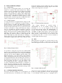
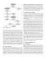
Figure 2 shows the circuit arround the MCP73833. In the
prototype of the tag two LEDs are integrated. A green
LED lights up when the battery is fully charged, the
yellow LED lights up when the battery is charging. A
10 kΩ resistor (R3 ) is used to limit the charge current to
a maximum of 100 mA [1] . This value is chosen so that
from such a battery can be as high as 4.2 Volt. A voltage
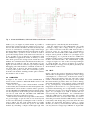
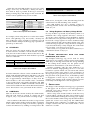
regulator is implemented on the tag. Figure 3 shows the
circuit of this step down converter.
Fig. 3. 3.3 Volt Step Down Converter
The voltage reduction is realized using a
TPS62291DRV IC. It can handle currents with a
maximum of 1 A. JP1 (see Figure 3) can be used
for powering external circuits. The TPS62291DRV is a
DC/DC converter and switches at a fixed frequency of
2.25 MHz. At light load it enters a power save mode.
The device uses 15 µA when there is no output current.
With a battery voltage between 3.8 Volt and 4.2 Volt
an efficiency from 90 % or more can be reached for
currents higher than 0.6 mA [2].
2.3
GPS
When the device is placed in a location where no WiFi localization is possible, a GPS receiver can be used
when GPS signals can be received. The circuit from the
Fig. 2. Battery Charger Circuit
it is possible to charge the tag from any standard USB
2.0 port, some motherboards power down the USB port
if the current given by the port is to high. Default USB
2.0 ports can also deliver 500mA, but this needs some
digital negotiation. To use this feature extra hardware
needs to be implemented on the tag. Some batteries have
an integrated thermistor. By measuring the resistance of
this thermistor, the charger can lower the charge current
when the battery becomes too hot. The battery used
in our design doesn’t have a thermistor inside so R4
is used to mislead the battery-charger. A resistance of
10 kΩ represents a thermistor at 21◦ C. The battery can
not be overcharged, the MCP73833 has an end-of-charge
control circuit inside. Also an automatic recharge circuit
is implemented in the IC [1].
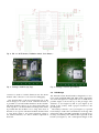
Fig. 4. A1035-H GPS Receiver
2.2
3.3 Voltage Step Down Converter
The Wi-Fi and GPS modules are not designed to be
powered directly by a LiPo-Battery. The output voltage
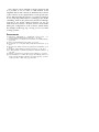
GPS receiver is show in Figure 4. The receiver is powered
by the 3.3 voltage step down converter. The prototype
of ”the Multiple Technology Tag” is equipped with a