1
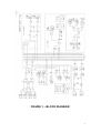
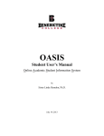
T L Audio
User Manual
FAT TRACK Tube Production Suite
TL Audio Limited, Letchworth, England.
Tel 01462 492090, Fax 01462 492097.
www.tlaudio.co.uk
email: [email protected]
CONTENTS.
CONTENTS.................................................................................................................................................... 1
INTRODUCTION ......................................................................................................................................... 3
PRECAUTIONS ............................................................................................................................................ 4
FIGURE 1 – BLOCK DIAGRAM .............................................................................................................. 5
INSTALLATION........................................................................................................................................... 6
AC MAINS SUPPLY. ..................................................................................................................................... 6
CHANNEL MICROPHONE INPUTS. ................................................................................................................ 6
CHANNEL LINE INPUTS. ............................................................................................................................... 7
INSTRUMENT INPUTS.................................................................................................................................... 7
INSERTION POINTS. ...................................................................................................................................... 7
DIRECT OUTPUTS, L/S OUTPUTS AND FX SEND. ....................................................................................... 8
UNBALANCED OUTPUTS .............................................................................................................................. 8
PHONES AND TAPE OUTPUTS....................................................................................................................... 9
BALANCED XLR OUTPUTS.......................................................................................................................... 9
VENTILATION. .............................................................................................................................................. 9
OPERATION. .............................................................................................................................................. 10
INPUT SELECTION ....................................................................................................................................... 10
CHANNEL GAIN CONTROL ......................................................................................................................... 10
LINE INPUT ................................................................................................................................................. 10
INSTRUMENT INPUT .................................................................................................................................... 10
MICROPHONE INPUT ................................................................................................................................... 10
PHANTOM POWER. ..................................................................................................................................... 11
PHASE REVERSE ......................................................................................................................................... 11
HIGH PASS FILTER...................................................................................................................................... 11
30DB PAD ................................................................................................................................................... 12
EQUALISATION ........................................................................................................................................... 12
INSERTION POINTS...................................................................................................................................... 13
EFFECTS SEND ............................................................................................................................................ 13
DIRECT OUTPUT ......................................................................................................................................... 13
PAN CONTROL ............................................................................................................................................ 14
MUTE SWITCH ............................................................................................................................................ 14
CHANNEL FADER ........................................................................................................................................ 14
TUBE STAGE DRIVE AND PEAK LED S....................................................................................................... 14
STEREO ROTARY RETURN CHANNELS ...................................................................................................... 14
MAIN SELECT BUTTONS ............................................................................................................................ 15
MAIN FADER .............................................................................................................................................. 15
EFFECTS RETURN ....................................................................................................................................... 15
MASTER INSERTION POINTS ...................................................................................................................... 15
PHONES LEVEL 1 - PRODUCER .................................................................................................................. 15
PHONES LEVEL 2 – ARTIST ........................................................................................................................ 15
MONITOR LEVEL ........................................................................................................................................ 16
ALTERNATIVE LOUDSPEAKER ................................................................................................................... 16
LOUDSPEAKER MUTE ................................................................................................................................. 16
MONITOR SOURCE ...................................................................................................................................... 16
OUTPUT VU METERS AND PEAK LED S. ................................................................................................... 16
DIGITAL OUTPUT O PTIONS ........................................................................................................................ 17
A FINAL WORD .......................................................................................................................................... 17
TIPS ON OPERATION.............................................................................................................................. 18
RECORDING A VOCAL TO YOUR DAW VIA THE FAT TRACK ................................................................... 18
SUMMING VIA THE FAT TRACK ................................................................................................................. 19
1
WARMING UP A STEREO MIX VIA THE FAT TRACK.................................................................................... 20
SPECIFICATIONS ..................................................................................................................................... 21
FOUR 2-TRACK RETURNS: ......................................................................................................................... 22
MAIN OUTPUTS: ......................................................................................................................................... 22
FX SEND:.................................................................................................................................................... 23
FX RETURNS: ............................................................................................................................................. 23
MONITORING: ............................................................................................................................................. 23
POWER REQUIREMENTS: ............................................................................................................................ 24
SERVICE ...................................................................................................................................................... 25
2
INTRODUCTION
Congratulations on your purchase of the TL Audio Fat Track Tube Production Suite
the complete solution for tracking, summing and monitoring.
Designed to be the centrepiece of any home, project or professional studio, this unit
combines some of the best-loved TL Audio features into one compact and professional
unit, adding warmth and sonic pleasure to all recordings and mixes. Drawing on our
larger and highly acclaimed M series consoles; the Fat Track offers you that unrivalled
big desk sound in a more compact, intuitive and affordable package.
The Fat Track can capture your recordings with two premium TL Audio tube preamps
as used on our M Series consoles contained within two fully featured channel strips
with 3 band swept musical EQ taken from our M1 console. Use the Fat Track for
summing and mix-down also, with 4 stereo and two mono returns. You will
immediately become aware of the richness and clarity of sound you gain when
summing your audio analogue via the Fat Track. You can even bring your entire mix
back via the 2 mono channels to add some EQ or final warmth, patch in a compressor
to the master inserts and suddenly you have a complete mastering solution too!
The monitor section also comes packed with features, including, separate return solo
and selection buttons, effects return, alternative loudspeaker mode, loudspeaker mute,
and 2 headphone outputs with individual rotary control. Headphone output 1
(producer) also follows your selections in the master section, whilst headphone output
2 (artist), stays fixed on the stereo bus to enable you to create a separate cue mix for
your client.
The multitude of inputs and outputs available within easy reach on the top panel
makes for a flexible and intuitive workstation where quick cable changes are made
easy. Space for fitting a TL Audio DO-8 ADAT interface is also provided allowing
easy digital connectivity.
Designed for the producer, musician, singer/songwriter, engineer or general enthusiast,
this product caters for every requirement, is easy to use and produces fantastic,
professional results.
3
PRECAUTIONS
The TL Audio FAT TRACK requires very little installation, but like all electrical
equipment, care must be taken to ensure reliable, safe operation. The following points
should always be observed:
- All mains wiring should be installed and checked by a qualified
electrician,
- Ensure the mains operating voltage stated on the rear panel is correct
before connecting to the mains supply,
- Never operate the unit with any cover removed,
- Do not expose to rain or moisture, as this may present an electric
shock hazard,
- Replace the fuse with the correct type and rating only.
Warning: This equipment must be earthed.
4
FIGURE 1 – BLOCK DIAGRAM
5
INSTALLATION
AC Mains Supply.
The unit is fitted with an internationally approved 3 pin IEC connector. A mating
socket with power cord and mains plug is supplied. All mains wiring should be
performed by a qualified electrician with all power switched off, and the earth
connection must be used.
Please note that when using this unit with alternate supply voltages (in foreign
countries, for example) the internal wiring of the unit may be set for 115V (accepting
voltages in the range 110V to 120V, 60Hz AC) or to 230V (for voltages in the range
220V to 240V, 50Hz AC). If the wiring needs to be changed, the unit must be taken to
an approved service centre.
Alternate supply voltages may also require a different power cable or mains plug. If in
doubt, consult local electrical regulations.
Warning:
attempted operation on the wrong voltage setting, or with an
incorrect fuse, will invalidate the warranty.
Channel Microphone Inputs.
Each mono input channel has a female, 3 pin XLR connector, for connection to a
microphone. The microphone will normally be balanced, but unbalanced connections
may also be made as follows:
Balanced inputs:
- Pin 1 = Ground (screen).
- Pin 2 = Signal Phase (“+” or “hot”).
- Pin 3 = Signal Non-Phase (“-” or “cold”).
Unbalanced inputs:
- Pin 1 = Ground (screen)
- Pin 2 = Signal Phase (“+” or “hot”).
- Pin 3 = Ground ( screen or connect screen to pin 1 and connect pins 1 & 3
together ).
When using unbalanced signals, the signal ground may be obtained by linking pins 1
and 3 in the mating XLR connector. Do not leave pin 3 open circuit, as this may result
6
in a loss of level and/or increased noise. Good quality screened cable should be used,
particularly for microphone or low level sources, to prevent hum or noise pickup.
Channel Line Inputs.
The line inputs are connected via a stereo TRS jack connectors. These may be wired to
accept balanced or unbalanced connection as follows:
Balanced inputs:
- Sleeve = Ground (screen).
- Tip = Signal Phase (“+” or “hot”).
- Ring = Signal Non-Phase (“-” or “cold”).
Unbalanced inputs:
- Sleeve = Ground (screen)
- Tip = Signal Phase (“+” or “hot”).
- Ring = Ground ( or connect screen and ring together )
Note: When using unbalanced connection on 3 pin plugs, the ring must be linked to
the sleeve to avoid possible reduction in level and/or increase in noise. ( alternatively a
2 way mono TRS jack may be used )
Instrument Inputs.
A 2 way (mono) jack plug is required, which should be wired as follows:
- Tip =
Signal Phase (“+” or “hot”).
- Screen = Ground.
Insertion Points.
The insertion points on the input channels and stereo mix are balanced, with separate
send and return sockets. They are “half normalled” i.e. a plug inserted into the send
socket (to derive an additional output) will not break the signal path through the
channel, but a plug inserted into the return socket will override the signal through the
channel.
Mating plugs may be wired for balanced or unbalanced connection as follows:
7
Balanced sends and returns, (using stereo TRS Jack connectors) :
- Sleeve = Ground (screen).
- Tip = Signal Phase (“+” or “hot”).
- Ring = Signal Non-Phase (“-” or “cold”).
Unbalanced send and returns: (using stereo TRS Jack connectors)
- Sleeve = Ground (screen)
- Tip = Signal Phase (“+” or “hot”).
- Ring = Ground (screen)
(Alternatively a mono TRS Jack may be used for unbalanced signals wired hot to tip,
screen to sleeve). Balanced connection is always preferable in an audio system, where
the equipment being connected supports it. It is possible to mix balanced and
unbalanced connections, for example using unbalanced sends and balanced returns,
with no loss in level.
Direct Outputs, L/S Outputs and FX Send.
These outputs all use balanced TRS jack connectors, which may also be wired for
balanced or unbalanced connection as follows:
Balanced outputs:
- Sleeve = Ground (screen).
- Tip = Signal Phase (“+” or “hot”).
- Ring = Signal Non-Phase (“-” or “cold”).
Unbalanced outputs:
- Sleeve = Ground (screen)
- Tip = Signal Phase (“+” or “hot”).
- Ring = Ground (screen)
Unbalanced Outputs
A 2 pin (mono) jack plug is required, which should be wired as follows:
8
- Tip =
Signal Phase (“+” or “hot”).
- Screen = Ground.
Phones and Tape Outputs.
These outputs are unbalanced, stereo signals, on TRS jack connectors. The mating
connectors should be wired as follows:
- Sleeve = Ground (screen)
- Tip = Left channel
- Ring = Right channel.
Balanced XLR Outputs.
The outputs are via balanced, 3 pin male XLR connectors. The mating connectors
should be wired as follows:
- Pin 1 = Ground (screen),
- Pin 2 = Signal Phase (“+” or “hot”),
- Pin 3 = Signal Non-Phase (“-” or “cold”).
If an unbalanced output is required, pins 1 and 3 should both be connected to ground.
Ventilation.
The unit generates a moderate amount of heat internally, which should be allowed to
dissipate by convection through the grills in the front panel, which must not be
obstructed. Do not locate the unit where it will be subject to external heating, for
example, in the hot air flow from a power amplifier or on a radiator, or in direct
sunlight. Ensure that air is able to circulate freely around and under the unit. The Fat
Tracks power supply and power transformer has been mounted to the back of the unit
to dissipate the heat created by these parts away from the main console and circuitry
and ensuring that the unit stays cooler and maintains longevity.
The FAT TRACK has been designed for operation free standing on a tabletop.
9
OPERATION.
Input Selection
You must ensure that the correct input connector, mic, instrument or line, is being
used from the required source. You can select the type of input by pressing the 'LINE'
switch at the top of each channel strip in or out. In the "up' position the mic input is
selected; depressing the 'LINE' switch selects the line input or instrument input as the
source. Note that you can have mic and a line / instrument input connected at the
same time but you will only be able to select a single input at a time. (NB do not have
anything connected to the line input when you have an instrument plugged into the
instrument input unless you want to combine 2 signals on the channel. Not
recommended)
Channel Gain Control
The gain control should be set to obtain the best signal to noise ratio, whilst preserving
adequate headroom. (i.e. as high as possible without causing signal distortion ) Any
changes in gain level should be gradual to avoid sudden overload or severe distortion.
Extra care should be taken with higher level inputs, and high gain settings should be
used sparingly to avoid an increase in the noise floor and the introduction of distortion.
Line Input
A typical line input will require less gain than a microphone signal, as it is a 'hotter'
source. You should have the gain set to a minimum when connecting a line input,
then gradually increase it to achieve the required level.
Instrument Input
A typical instrument level input will be lower in level than a line level signal but you
should still exercise caution with the gain, starting at a minimum setting and slowly
increasing until desired setting is reached. When connecting an instrument like guitar,
you can connect straight into the Fat Track without the need for an additional DI unit
or amplification stage, the Fat Track’s input stage acts as both your DI and preamp.
Microphone Input
When connecting a microphone to the Fat Track, start with the gain set to a minimum
value and gradually increase until the sound source is just tickling 0dB on the meters
when the source sound is at average output level. You can than choose how much you
would like to drive the valves to produce the required sound. If Phantom power is
10
needed, activate it before setting the gain by depressing the button marked '48V' on the
channel strip. Although the Fat Track provides 48V of phantom power, microphones
requiring less than 48V can still be connected without any difficulties.
Phantom Power.
+48V phantom power is available at the mic socket, selected by a front switch.
Phantom power should only be used in conjunction with suitable condenser
microphones. ( Phantom power will not damaged other types balanced microphones
apart from ribbon mics, if you have no unbalance or ribbon mics it is usually OK to
leave the phantom power on subject to the caution below )
CAUTION: Operation of the phantom power switch, or plugging a microphone in or
out with phantom power applied, may cause a click or thump in your loudspeakers.
To prevent this happening, ensure that the system gain is set to minimum (e.g. on your
mixing console fader or power amplifier), before operating the switch or plugging in a
microphone.
Phase Reverse
The phase reverse switch is used to invert the phase of the input signal. It is active on
both mic and line inputs. This function could be required when processing a signal
that is out of phase with other signals in a mix, in which case the resultant phase error
typically appears as a loss of low frequency content, due to cancellation of out of
phase components. Phase reverse is commonly used when recording the bottom of a
snare drum (if also using a mic on top of the snare), the back of a guitar cab (if also
recording signal from the front of the cab), and when performing the stereo recording
technique known as an MS pair. If 2 sources of the same audio signal are mixed
together in mono and one is out if phase with the other ( e.g. pins 2 and 3 are wired
incorrectly on one of the inputs ) then cancellation will occur. To demonstrate this
plug a stereo mix into the 2 channels pan 1 left and 2 right and play back – now select
the phase reverse switch on one of the channels, no cancellation yet but you should
detect a loss of bass and a loss in the stereo imaging, you may also feel a slight
pressure in the ear but you will hear the whole of the stereo recording. Now put both
pans to the centre and the whole centre of the mix will disappear, you will only hear
those parts of the signal which were panned fully left or fully right in the mix, the part
of the stereo mix which was common to left and right, the singer for instance, and bass
guitar and bass drum etc. will all have disappeared. Out of phase signals can be used
to great effect sometimes but NEVER if you are mixing for vinyl. It is not possible to
cut a vinyl master if the final mix contains out of phase signal.
High Pass Filter
This low cut filter provides 12dB per octave of gain reduction with the -3dB point
being at 90Hz. Like the phase reverse switch, the high pass filter is active on mic,
instrument and line inputs, and is ideal for removing low frequency rumble. The filter
can be useful in restricting 'popping' on vocals or even low frequencies caused by
11
contact with microphone stands or microphone cables. Popping is an undesirable
thump that is caused by close-miking certain spoken or sung letters, namely 'P' or 'B'.
These particular letters cause a sudden expulsion of air that can result in an audible
thump. As this thump has a lot of low frequency content the high pass filter can help
to reduce the problem, as can using a pop filter (a device usually made out of nylon
material similar to stockings) suspended in front of the microphone. The low cut filter
is easily bypassed for quick A/B comparison.
30dB Pad
Occasionally when using sensitive condenser microphones the source signal may be
too loud for the input preamp. In this situation, to avoid any overloading or distortion
of the mic preamp stage, the 30dB pad can be used to reduce the input gain to a more
manageable level. The 30dB pad only applies to the microphone input.
Equalisation
Before switching the EQ into circuit, it is advisable to set the cut/boost controls to
their centre, or flat, position. The EQ is brought into circuit with the 'EQ ON' push
switch, located at the top of the channel strip. Each channel has three bands of
equalisation:
1/. shelving wide band low frequency (LF) (i.e. it extends from 80Hz to the extreme
low frequency limit of the equaliser's response.),
2/. peaking sweepable mid (i.e. it boosts or cuts a section of the audio spectrum around
its selected centre frequency only)
3/. shelving wide band high frequency from 12 kHz to the extreme high frequency
limit of the equaliser’ response (HF).
The LF shelf operates at a frequency of 80Hz, while the HF shelf is set at 12kHz. The
EQ slopes have a second order 12dB/octave response, and an associated gain control
on both bands provides up to 15dB of cut or boost on each selected frequency,
controlling the full range of frequencies below the LF corner frequency and above the
HF corner frequency. The mid band has a fixed Q of 0.7 allowing +/- 15dB cut or
boost over a moderately broad band of frequencies. The centre frequency is selected
via the dedicated variable frequency control, and the required amount of cut or boost is
applied using the associated gain control. The range of frequencies selectable is 150Hz
to 7kHz.
When listening to a mix, it is generally frequencies between around 40Hz and 1214kHz that the ear is most sensitive to and a distinct lack of any one frequency in
between these figures can result in a mix that may lack ‘fullness’. Generally, a
pleasant mix will contain a good balance of frequencies from across the spectrum.
Each part of the frequency spectrum does however contribute its own unique
characteristic. For instance, if there is too much low frequency content below around
300Hz, the mix can sound ‘boomy’ or ‘muddy’. Too little presence from these
frequencies however and the mix can sound ‘thin’ and lacking ‘power’ or ‘energy’.
12
Too much energy in the low mids (around 300Hz – 2kHz) can cause a really ‘middy’
sound which lacks drive and excitement. The mid ranges are very important, as it is
within these ranges that your vocal and lead instruments will be most prominent so it
is essential that you get a good balance. Finally, towards the top of the listening
spectrum, frequencies here are generally adding sparkle and a sense of space to your
overall mix. Lack of energy from as low as 2kHz can cause the mix to sound dull
whilst to much top and your mix will sound overly bright. But take care with the top
end as most of the hiss associated with recording is within the range of the high
shelving (HF), to reduce excessive noise it is better to record with too much top and
wind it off when mixing than vice versa.
You should frequently A/B the sound you are Equalising by pressing and depressing
the EQ ON button; it is astonishing how quickly the ear can adjust to changes. By
making frequent comparisons you can make sure you do not stray from the required
sound. It is also worth spending some time getting used to the EQ on the Fat Track - it
sounds great and you'll be amazed how versatile and musical it can be.
Insertion Points
The insert points are configured to be post the input amplifier with its valve stage, but
pre EQ and fader. Typical applications include the connection of a compressor (for
example the TL Audio Ivory 5021) into the channel, or perhaps a gate (usually for
percussive sounds) or a dedicated outboard equaliser (e.g. the TL Audio Ivory 5013)
for extensive EQ correction or effect.
The inserted device can easily be switched on and off for A/B comparison and
flexibility via the ‘INSERT ON’ button at the bottom right of each channel strip.
As the insert points are balanced, you could also use the insert send as an additional
direct output. This would give the benefit of a short path audio circuit, but remember
that the insert send is pre EQ and pre Fader.
Effects Send
Effects sends are available on each channel to provide you with the ability to send
signal to an effects processor (typically a reverb).
The effects send rotary knob controls the amount of signal that is sent from the
channel to the effects unit. Playing with the amount of signal you send and the level
you set the Effects return knob at will greatly differ the severity of the chosen effect.
Direct Output
Direct outputs are provided from both channels to connect directly to your computer
soundcard or recording device via balanced analogue jacks. The direct output is post
Insert, EQ, and Fader but pre Mute.
13
Pan Control
The pan control positions the image within the stereo field, from fully left in the
anticlockwise position, through centre at the dented position to fully right in the
clockwise position. The gain law is -3dB at the centre.
Mute Switch
The channel may be muted or switched on without affecting the level set on the
channel fader.
Channel Fader
A rotary fader is located at the bottom of each of the input channels, and sets the level
of the channel's signal being fed in to the stereo mix bus or to the direct output. The
fader provides up to 10dB of gain at its highest point.
Tube Stage Drive and Peak LEDs.
The yellow LEDs indicate the drive level to the tube, or valve, stage. The Drive LED
is a variable intensity indicator, starting to glow when the tube harmonic distortion is
around 1%, and being fully illuminated at approximately 5% harmonic distortion. The
distortion generated by the tube stage is predominately second harmonic, which is
responsible for the characteristic valve “warmth”. The red Peak LED operates as a
conventional warning that clipping is about to occur. The operating level of both input
and post fader stages is monitored, and the LED illuminates at a threshold of +19dBu,
when there is less than 7dB of headroom remaining to the direct output. Normal
operation would be to set the input gain so that the Drive LED is illuminating
regularly, with occasional illumination of the Peak LED occurring on loud transients.
Stereo Rotary Return Channels
4 stereo return channels are provided for routing multiple outputs in via your computer
soundcard / DAW into the Fat Track for summing and/or mix down. The rotary level
control enables you to control the level of the input signal or create a basic mix of the
levels coming in. For work that has already been mixed but you would like to just
sum the audio through the Fat Track for optimum sound and fantastic results, it is
quite normal to have these rotary return levels set to their maximum (10). Please note
you can use the mono channels as input returns too, via the line input sockets on each
channel; this gives you a maximum of 10 return paths (4 stereo and 2 mono). All
stereo return sockets are selectable between +4 and -10dB.
14
Main Select Buttons
The ‘MAIN’ switch located in the centre of the unit just above each corresponding
rotary stereo return knob (A,B,C,D) activates the return and routes it into the stereo
bus. To activate the main switch it needs to be pressed to its downward position. The
‘MAIN’ switch can be used as an ‘ON’ switch to route the stereo signal to the stereo
bus, or as a ‘MUTE’ switch when it is de-selected.
Main Fader
The main rotary fader controls the main output level and also drives the final tube dual
triode ECC83 tube stage on the master output.
Effects Return
The Effects Return Rotary knob is located above the Main fader and the headphone
levels, and controls the level of the signal coming back from your effects processor to
be fed into the stereo mix. Playing with the amount of signal you send and the level
you set the Effects return knob at will greatly differ the severity of the chosen effect.
As it is a stereo return that feeds the stereo bus you could also use the return as an
additional stereo input when summing or mixing.
Master Insertion Points
Balanced inserts are offered in the master section too. This enables you too connect a
piece of hardware like a stereo compressor or limiter for an easy mastering solution.
The inserted device can easily be switched on and off for A/B comparison and
flexibility via the ‘INSERT ON’ button just above the main rotary fader control.
Phones Level 1 - Producer
This rotary control controls the level sent to headphone output 1 (producer). It is fed
from the monitor section and will follow what is selected within that section. This
means that by default it will monitor the stereo bus/ main mix, unless you select one,
or any number of the stereo return (A-D) buttons and it will then switch to monitor
what has been soloed.
Phones Level 2 – Artist
Phones level 2’s (artist) rotary control, controls the level of the signal fed to
headphone output 2. This output always feeds from the stereo bus / main mix even
when returns are in solo mode. This means headphone output 2 is ideal for the artist
or client to listen to for a constant, uninterrupted listening experience.
15
Monitor Level
This ergonomically satisfying knob controls the volume of the monitor speakers
connected to the Fat Track.
Alternative Loudspeaker
By selecting the ‘ALT LS’ switch in the master section it allows you to switch your
monitoring to an additional set of monitor speakers . This is great for A/B
comparisons and for switching between near-field and mid-field monitors. A great
feature for mixing and mastering.
Loudspeaker Mute
This switch mutes the monitor and alternate LS outputs. This is particularly useful
when using headphones, enabling the main monitors to be muted without needing to
turn off their amplifiers. It is also useful for temporarily muting the monitors without
needing to alter any fader levels, for instance during a telephone call.
It is good practice to mute the outputs when switching the Fat Track on or off, to avoid
any loud “thumps” in the loudspeakers.
Monitor Source
Located in the master section on the far right of the console, these 4 buttons labelled
A, B, C, D allow you to solo the corresponding stereo return, you can select multiple
returns to solo at any one time, in any combination, and once all buttons are
deselected, you will automatically switch back to monitoring the ‘main’ stereo bus.
Output VU Meters and Peak LEDs.
The two VU meters monitor the level on the stereo output. The meters are factory
calibrated for 0VU = +4dBu on the balanced XLR outputs (-10dBu on the unbalanced
outputs). The calibration may be changed by inserting a small screwdriver through the
holes labelled “0VU” in the front panel underneath the Peak LEDs. There is a 3
segment LED meter adjacent to each VU meter. The LEDs indicate peak levels of
0dB, +6dB and +12dB. The LED calibration is fixed, and not affected by changes to
the VU meter calibration.
16
Digital Output Options
The optional DO8 card can be fitted to the back of the Fat Track, providing an 8channel ADAT lightpipe I/O interface. This professional protocol makes for easy
connection when conducting computer-based recording or when connecting to other
digital equipment. It provides you with digital access to channel direct outputs, master
stereo output, 4 stereo returns and both channel line inputs, a total of 10 inputs and 4
outputs.
A button is located at the top left hand side of the console amongst the I/O sockets that
enables you to configure the digital signal. When the button is in it’s up position,
digital inputs 7&8 or routed to stereo return ‘D’, when the button is in its downward
position, digital inputs 7&8 are routed to channels 1&2. This gives you access to all
10 channels with a push of a button.
A Final Word
We are confident that you will enjoy this new addition to your set up and may soon
wonder how you use to manage with out it!
If you do have any questions regarding this product or operation, contact us
[email protected] or +44 (0) 1462 492 090.
17
TIPS ON OPERATION
Recording a Vocal to your DAW via the Fat Track
To set up the Fat Track for a basic recording of a single vocal, you can use the
following instructions as a simple guide to get started. It is up to you how you wish to
use and operate the equipment, and the following is meant as a guide only,
highlighting one of many possible ways in which to record.
1. Connect your microphone cable to the 3-pin XLR connector at the top of one
of the channel strips, and check the Mic / Line switch is set to the ‘MIC’
position. If you are using a condenser (capacitor) microphone you should also
press the 48V phantom power switch - please ensure that you have the gain
and master volume down when you activate this switch as turning on the
Phantom Power can cause a loud pop which could potentially damage your
monitor speakers. Make sure you are using a balanced microphone cable.
2. If you are recording in a room where the acoustics are not ideal or there is
background noise / electrical hum, you may find it useful to activate the 90Hz
High Pass Filter, this will get rid of some of the unwanted noise from your
vocal recording
3. Test the input signal level by asking your vocalist to warm up while you
gradually step up the gain until you are getting an adequate level coming
through, you can monitor this via the analogue VU meters and by being aware
of the LED indicators. If you are recording straight to your DAW via the
direct output on the channel, you should also check your signal input level on
your chosen music software. Please note that on the Fat Track you can push
the channels and have the levels ‘tickling the red’ as it is a fully analogue
device, however, on your software interface you should never let it clip in the
red as it would result in a square wave digital clip. Once you think you are
happy with the level, ask your vocalist to sing the loudest and quietist part of
the song and make any necessary adjustments. The most important thing is to
avoid clipping, quiet parts add to the dynamic range of a vocal and can easily
be evened out via compression at the mix stage. If you are experienced in
recording you may find it better to use a compressor which recording as this
will control the dynamic range of the signal and make distortion at the DAW
less likely.
4. To listen to the stereo mix you are tracking to, bring back the main output of
the DAW / soundcard to one of the stereo returns (A-D) and then set
headphone levels to a comfortable volume for your vocalist and yourself.
Obviously there are other ways you can configure your set up and monitoring
due to the flexible I/O and routing / monitoring available on the Fat Track.
5. Now you are ready to go, so simply press record in your DAW and let the
vocalist do their work.
18
Summing via the Fat Track
One of the big audible benefits you will be aware of with the Fat Track is its ability to
sum your sounds together in analogue to produce a more detailed, open, rich, warm
and dynamic sound.
Summing is basically another term for what is essentially mixing, but in its most basic
form. Summing, as the name would suggest is the process of adding several different
signals together into one combined signal.
In software, the summing is done digitally using algorithms to mathematically add the
individual parts including all note, pitch, volume, control and effects information.
This large calculation can mean that the result is not always that accurate or that some
information may become lost, confused or blurred during this process.
Analogue summing has long been proven as a more reliable and pleasant sounding
way of adding signals together and the Fat Track lets you do this very easily.
The following is a basic guide as to how you can use the Fat Track to sum your audio.
In this example we presume you are summing from a DAW.
1. Once you have finished your mix in your software of choice, start to group
your mix via type of instrument (i.e. ‘vocals’, ‘percussion’, ‘rhythm’, ‘lead’
etc), grouping the individual channels to their assigned bus within your
software. This creates mixed stereo stems of all the components of your track.
2. For mono signals that you may not want to group (like lead vocal or bass
guitar) these can be kept in mono and either fed out from the channel or a
mono bus output.
3. You can then connect up to 10 (4 stereo and 2 mono) channels to the Fat Track
depending on the number of outputs you have from your soundcard / audio
interface. If you have ADAT connections on your soundcard, you could also
use the TL Audio DO-8 interface with the FAT Track to enable you to access
the outputs over ADAT (see details in operation).
4. Use the level controls for the stereo returns to make any adjustments in level
between the different groups of instruments.
5. If you want to add any dynamics, like compression to your mix, you can insert
them via the balanced inserts provided on the master section.
6. You can then take the output from the Fat Track back into your soundcards
inputs to record the Fat Tracks analogue sum of your mix back into your
software (beware to make sure you do not have the summed signal going back
in to your software, being fed back into the Fat Track – otherwise a feedback
loop may occur).
19
Warming up a stereo mix via the Fat Track
Sometimes you may just want to inject some life into, or warm up your final stereo
mix. It is very easy to do this with the Fat Track, giving you a great sounding back end
to your DAW or general recording set up. Having a quality analogue back end to your
system can put soul and life back into your recordings, taking away that clinical, dull
sound.
You do not have to make it sound ‘coloured’ though, run your mix through without
any added EQ to simply open up your sound giving more clarity and definition. Or
you can use the musical, British EQ section to add some warmth, sparkle and depth to
your mix.
If you are not sure where to start with EQing a stereo mix, it may be useful to start
with the ‘smile curve’ EQ boost. This principal is used in many Consumer HiFi and
Pro Audio Exciter effects to enhance the sound. The curve consists of a small boost in
the low, a small boost in the high, and either a small cut or a flat response for the mid.
By all means play around with the EQ on the Fat Track to create your desired sound,
but remember only small changes should be made to a finished mix otherwise your
result may become imbalanced. Less is more! The EQ section on the Fat Track is
taken from our M series consoles and is very smooth and musical; this means that you
can push your settings a little further whilst still maintaining a pleasant sound.
1. Connect your stereo mix from your source (DAW / Master Tape) via the line
inputs on each channel
2. Make sure you have the channels switched to ‘LINE’ and also have the pan
controls turned ‘LEFT’ and ‘RIGHT’ for each side of your mix.
3. You may then add any EQ cuts or boosts that you require, it is sensible to
frequently A/B your EQ changes by switching the ‘EQ ON’ button in and out
for comparison. You ear can very quickly get used to EQ changes so it is
always wise to keep referring to your original.
4. There is the option of using the Fat Track as a complete mastering device too,
by patching in a stereo compressor / limiter to the balanced inserts on the
master bus. Again you can A/B your changes from the Fat Track directly, by
using the ‘INSERT ON’ button to switch the dynamic processor in and out.
5. When you are happy with your sound, you can then simply take the stereo
output (either main balanced, main unbalanced, or tape out) from your Fat
Track to your main recording device.
20
SPECIFICATIONS
2 Input Channels (figures quoted to Direct Outputs with Fader at maximum):
Line Input:
Balanced, via 3 pin TRS jack.
Nominal Level +4dBu, Gain range +/-20dB.
Frequency Response 10Hz to 40KHz, +/-0.4dB.
Maximum Input Level +22dBu.
Noise -83dBu unweighted, 22Hz to 22KHz.
Mic Input:
Balanced, via 3 pin XLR.
Gain range +16dB to +60dB (-14dB to +30dB with pad).
Input Noise (EIN) -127dBu, 22Hz to 22KHz @ 60dB gain,
Frequency Response 10Hz to 40KHz, +/-0.5dB, @ 40dB gain.
Maximum Input Level +6dBu (+36dBu with pad).
Switchable 48V Phantom Power.
Instrument Input:
Unbalanced 0.25” jack.
Nominal input -16dBu, Gain range +/-20dB.
Maximum Input Level +8dBu.
Frequency Response 10Hz to 40KHz, +/-0.5dB.
Noise -83dBu unweighted, 22Hz to 22KHz.
Direct Output:
Post EQ and Fader, Pre Mute Switch.
Balanced, via 3 pin TRS jack.
Nominal Level +4dBu.
Maximum Level +22dBu.
Mono Inputs:
Phase Reverse Switch.
Switchable High Pass Filter, -3dB @ 90Hz, 2nd order.
Equaliser:
“High” +/-15dB @ 10KHz.
“Mid” +/-15dB, swept 150Hz to 7KHz, Q =0.7.
“Low” +/-15dB @ 80Hz.
Tube Stage:
Pre EQ.
Drive LED:
Variable intensity, from 0dBu to +12dBu, indicating increasing
Tube drive. Distortion is predominately 2nd Harmonic,
increasing with Drive LED from 0.5% to 3% (typical).
Peak LED:
Illuminates at +19dBu.
Multiple point monitoring at Input stage and post EQ.
Insertion Point:
Post EQ, Pre Fader.
21
Semi-balanced Send, balanced Return, on separate 3 pin TRS
jacks.
Bypass switch.
Nominal Level -2.7dBu.
FX Send:
Post EQ, Fader and Mute switch.
Variable send level.
Routing:
To Main L+R stereo mix, via pan pot (-3dB at centre) and mute
switch.
Four 2-Track Returns:
Fader:
Rotary, 0dB maximum gain.
Inputs:
Balanced, via 3 pin TRS jacks.
Nominal Level individually switchable +4dBu/-10dBu.
Maximum Input Level +22dBu.
Routing:
To Main L+R stereo mix, via Fader and routing switch.
Main Outputs:
Fader:
Rotary, +10dB maximum gain.
Tube Stage:
Post Mix Amps.
XLR Outputs:
Balanced, nominal level +4dBu.
Maximum level +26dBu.
Noise, all faders @ 0dB, -80dBu, 22Hz to 22KHz.
Noise, Main Fader @ minimum, -95dBu, 22Hz to 22KHz.
Jack Outputs:
Unbalanced, nominal level -10dBu
Tape Output:
Combined TRS jack, nominal level -10dBu.
Insertion Point:
Pre Fader.
Semi-balanced Send, balanced Return, on separate 3 pin TRS
jacks.
Bypass switch.
Nominal Level -2.7dBu.
22
FX Send:
Output:
Mono, semi-balanced, via 3 pin TRS jack.
Nominal level -6dBu.
Noise -87dBu, channel sends @ maximum.
Noise -100dBu, channel sends @ minimum.
FX Returns:
Inputs:
Stereo, Right Input normalled to Left Input for Mono
compatibility.
Balanced, via 3 pin TRS jacks.
Nominal level +4dBu.
Maximum Input Level +22dBu.
Monitoring:
Source:
Normally follows Main Output, overridden by 2-Track AFL
selection.
Level controlled by large diameter knob.
Main / Alt LS switch.
LS Mute switch.
LS Outputs:
Main and Alt LS, balanced on 3 pin TRS jacks.
Nominal Level +4dBu.
Maximum Level +26dBu.
Noise -80dBu, all faders @ 0dB.
Noise -100dBu, Monitor Fader @ minimum or LS muted.
Phones Outputs:
2 stereo outputs, with separate level controls.
Phones 1 follow Monitor selection, for Engineer/Producer.
Phones 2 follow Main Output at all times, for Artist.
3 pin TRS jacks.
Minimum Impedance 32 ohms.
Digital I/O:
Optional DO-8/Firewire cards available, to fit slot on rear panel.
Dimensions:
381mm W x 330mm D x 150mm H. (15” x 13” x 6” approx).
23
Power Requirements:
Voltage:
230V 50Hz or 115V 60Hz, internally wired.
Consumption:
37VA, without digital I/O.
41VA, with DO-8 option fitted.
These specifications are typical figures, subject to normal production tolerances. They do not represent
guaranteed limits for any particular piece of equipment. Specifications are subject to change without
notice.
24
SERVICE
Should the unit require service, it must be taken or posted to an authorised dealer with
a description of the fault. Please retain the original packing for possible future use, and
ensure the unit is suitably protected during transit. The manufacturer cannot accept
responsibility for damage caused during transportation.
This equipment is supported by a limited warranty for a period of one year from the
date of purchase. During this period, any faults due to defective materials or
workmanship will be repaired free of charge. The warranty excludes damage caused
by deliberate or accidental misuse, tampering, operation on the incorrect mains
voltage, or without the correct type and value of fuse fitted. It is the user’s
responsibility to ensure fitness for purpose in any particular application. The warranty
is limited to the original purchase price of the equipment, and excludes any
consequential damage or loss.
Please record the following details, and retain proof of purchase date:
Serial Number.............................
Date purchased...........................
Dealer.........................................
TL Audio Limited, Letchworth, England.
Tel: 01462 490600. International +44 1462 490600
Fax: 01462 490700. International +44 1462 490700
www.tlaudio.co.uk
email: [email protected]
25