1
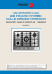
UM0789
User manual
Counter with STM8L101xx
low-power microcontroller and LCD
Introduction
The demonstration board STEVAL-IAS003V1 has been designed to be used as example for
applications where directly driven LCD and associated programmable functionality are
needed. Targeted applications are medical, healthcare, battery operated counters,
metering, among many others.
The board demonstrates STM8L101xx microcontroller low power consumption. The
demonstration firmware is consequently written to take advantage of the low power modes
available on this device. It allows to achieve an average current consumption lower than 1.6
µA for the whole application including the direct LCD software driver.
Figure 1.
September 2009
STEVAL-IAS003V1 demonstration board
Doc ID 16240 Rev 1
1/11
www.st.com
Contents
UM0789
Contents
1
Main features . . . . . . . . . . . . . . . . . . . . . . . . . . . . . . . . . . . . . . . . . . . . . . . 3
1.1
Used components . . . . . . . . . . . . . . . . . . . . . . . . . . . . . . . . . . . . . . . . . . . 3
1.2
Circuit schematic . . . . . . . . . . . . . . . . . . . . . . . . . . . . . . . . . . . . . . . . . . . . 4
2
Basic principles . . . . . . . . . . . . . . . . . . . . . . . . . . . . . . . . . . . . . . . . . . . . . 5
3
Additional features . . . . . . . . . . . . . . . . . . . . . . . . . . . . . . . . . . . . . . . . . . 7
3.1
LCD decoding . . . . . . . . . . . . . . . . . . . . . . . . . . . . . . . . . . . . . . . . . . . . . . . 8
4
Conclusion . . . . . . . . . . . . . . . . . . . . . . . . . . . . . . . . . . . . . . . . . . . . . . . . . 9
5
Revision history . . . . . . . . . . . . . . . . . . . . . . . . . . . . . . . . . . . . . . . . . . . 10
2/11
Doc ID 16240 Rev 1
UM0789
1
Main features
Main features
●
1.6 µA consumption @ 36 Hz refresh rate
●
3 digit LCD glass driven by software
●
2 buttons
●
CR1220 battery operated
●
Minimum external components:
–
1.1
only 2 capacitors on top of mandatory parts (battery, LCD, MCU, buttons)
●
Low-cost PCB (single layer)
●
RoHS compliant
Used components
●
1x STM8L101
●
1x 3 digit LCD glass, 23 segments, single common electrode
●
1x ceramic capacitor 47 nF on supply lines
●
1x ceramic capacitor 10 nF on RESET line
●
2x button
●
1x battery CR1220
●
1x PCB
●
1x SWIM connector (only for evaluation purpose)
●
1x jumper (only for evaluation purpose/ammeter connection)
Doc ID 16240 Rev 1
3/11
Main features
1.2
UM0789
Circuit schematic
Figure 2.
STEVAL-IAS003V1 schematic diagram
5
"UTTON?
0"
%
$
#
$0
%
$
#
$0
%
$
#
"
0
#
#AP3EMI
.#
)#
6SS
"UTTON?
%
$
#
$0
%
$
#
$0
%
$
#
"
!
&
'
"
!
&
'
"
!
&
'
#/-
!
&
'
"
!
&
'
"
!
&
'
#/-
,#$?DIGIT
0"
#
#AP3EMI
.#
6SS
6SS
"UTTON?
$0
#
$
%
37)
6DD
6DD
37)6SS
.234
4/11
(EADER
6DD
6DD
#
N&
0
(EADER
0
"
!
&
'
"
!
&
'
(EADER
#/%
$
#
"
!
&
'
0
0$
0$
0$
0$
0"
0"
0"
0"
0"
0"
0"
0"
0$
0$
0$
0$
6SS
0!
0!
0!
0!
0!
0!
633
6$$
5
34-,
0#
0#
0#
0#
0#
0#
0#
0!
.234
$0
#
$
%
"UTTON?
#
#AP3EMI
N&
"4
"ATTERY
6SS
6SS
!-V
Doc ID 16240 Rev 1
UM0789
2
Basic principles
Basic principles
The main task of this demonstration board is to drive an LCD display. There are different
ways to drive an LCD: the LCD can feature an integrated driver which communicates via an
SPI bus, or it can be controlled directly through its segments. This application directly drives
the LCD segments.
LCD glasses have plenty of segment electrodes, and one or several common electrodes. To
make a character or segment visible, a voltage level has to be applied between the segment
and the appropriate common electrode. To keep the character or segment invisible, a
voltage level equal to the common electrode voltage must be applied to segment 1.
To prevent electrolytic damage on liquid crystals, an AC voltage has to be applied on the
electrodes. As only DC supply voltage is available on the board, the MCU must change
regularly the voltage polarity between the segment and the common electrode.
Figure 3.
COM stands for common segment; SEG1 for segment 1; and SEG2 for
segment 2
#/6DD
6SS
3%'
6DD
6SS
3%'
6DD
6SS
!-V
For more details about LCD drive, please refer to AN1048 and AN2687.
In order to minimize current consumption, the STM8L101xx is kept in Active-halt low power
mode most of the time. The MCU is periodically woken up from this mode by an autowakeup timer. This timer is configured to wake up the MCU by generating an interrupt every
28 ms to achieve an LCD refresh rate of 36 Hz. This frequency is the best compromise
between consumption, which increases with the frequency, and flickering which appears at
low refresh rates
The interrupt service routine performs the toggling of LCD control signals to make sure
there is no DC bias between segments and common electrodes. The routine placement is
aligned with memory organization to fill STM8 pipeline prefetch buffers efficiently.
Doc ID 16240 Rev 1
5/11
Basic principles
UM0789
To save power, a new feature has been implemented on STM8L microcontrollers: when the
AL bit is set in the global configuration register (CFG_GCR) and the MCU is woken up from
low power mode, it goes back to low power mode as soon as the interrupt service routine
(ISR)execution is complete.
There is no need to restore the context, return to the main program and execute a HALT
instruction again.
6/11
Doc ID 16240 Rev 1
UM0789
3
Additional features
Additional features
Each button corresponds to a different ISR which allows to compare two possible solutions.
The functions performed by each ISR are identical but their implementation differs. Both
ISRs update the value shown on the LCD, refresh the LCD as long as the button is pressed
(AWU is disabled during this time), and perform a periodic test on the button.
Once the button is pressed, the MCU is woken up as long as the button remains pressed.
The MCU is consequently in full operating mode.
Several procedures to decrease power consumption have been used in demo application:
●
slowing down core frequency, when it brings an advantage
●
moving code to the RAM, when it brings an advantage
●
using WFE/WFI mode
●
dynamic pull up configuration for buttons
Slowing down the core frequency brings an advantage mainly if the MCU performs
periodically the same operation such as a button check. Once the MCU has entered the
deepest low power mode (Active-halt or Halt), slowing down the core results in higher
consumption than executing the code at high speed. Faster code execution changes the
ratio between Run mode and Active-halt/Halt mode, resulting in an overall lower
consumption.
The left button is associated with ISR code located in RAM memory. To slow down the core
and achieve lower consumption, the clock frequency is divided by a factor of 8. The ISR
consequently contains a single while() loop performing a sequence of NOP instructions and
button check. The approximate consumption in this mode ranges from 350 to 380 µA.
The right button is associated with ISR code located in Flash memory (main loop). The core
runs at high frequency while the instructions are executed. To save power, a brand-new Wait
for event mode is used.
In this mode, the core is stopped and waits for an event which is associated with a
peripheral, in this case timer 2 (TIM2). TIM2 generates a delay which replaces the while()
loop implemented in the Left button ISR. Once the MCU has entered low power mode, the
clock frequency is divided. In this mode, the approximate consumption ranges from 240 to
270 µA.
Once button is pressed, it will ground an associated pin. This pin has an internal pull up of
around 45 kΩ, connected to Vcc. It means that, a current of 67 µA is drawn from the battery
by the I/Os. To save on power consumption, a dynamic connection of this pull up is
implemented.
The pull up is set only for a short period of time when the software performs a check on the
button. It is then disabled. This sequence is repeated every 6.4 ms. It dramatically reduces
the current consumption on the I/Os.
The usual problem of extra consumption generated by the toggling of pins left floating does
not occur in this situation: a proper level is guaranteed while the button is pressed, except
for a few ms when the button is released. This time does not exceed one period of button
state check.
Timing is managed by TIM2 or by a software delay.
Doc ID 16240 Rev 1
7/11
Additional features
3.1
UM0789
LCD decoding
To allow using a single layer PCB, the LCD display is connected directly to IOs in the
simplest way from design point of view.
As a result, the software decodes directly the characters to control the corresponding IOs.
The following define statements must be used to associate the active segments with each
character to be shown on the LCD:
#define LCD_CHAR_0 (LCD_A + LCD_B + LCD_C + LCD_D + LCD_E + LCD_F )
The above definitions are stored in the LCD_VALUE[] array which contains all possible
character definitions. Simple indexing could be used to read the character definitions.
These definitions are then used by the decoding function to set the appropriate
STM8L101xx pins to 0 (invisible segment) or to 1 (visible segment).
To update the LCD, a simple inversion of all IOs is required. The common electrode is set to
0 during LCD update.
For LCD update, a simple inversion of all I/O's is used.
8/11
Doc ID 16240 Rev 1
UM0789
4
Conclusion
Conclusion
This example could be used for many different applications. User could modify the attached
software easily to implement any additional functionalities and features.
Doc ID 16240 Rev 1
9/11
Revision history
5
UM0789
Revision history
Table 1.
10/11
Document revision history
Date
Revision
17-Sep-2009
1
Changes
Initial release.
Doc ID 16240 Rev 1
UM0789
Please Read Carefully:
Information in this document is provided solely in connection with ST products. STMicroelectronics NV and its subsidiaries (“ST”) reserve the
right to make changes, corrections, modifications or improvements, to this document, and the products and services described herein at any
time, without notice.
All ST products are sold pursuant to ST’s terms and conditions of sale.
Purchasers are solely responsible for the choice, selection and use of the ST products and services described herein, and ST assumes no
liability whatsoever relating to the choice, selection or use of the ST products and services described herein.
No license, express or implied, by estoppel or otherwise, to any intellectual property rights is granted under this document. If any part of this
document refers to any third party products or services it shall not be deemed a license grant by ST for the use of such third party products
or services, or any intellectual property contained therein or considered as a warranty covering the use in any manner whatsoever of such
third party products or services or any intellectual property contained therein.
UNLESS OTHERWISE SET FORTH IN ST’S TERMS AND CONDITIONS OF SALE ST DISCLAIMS ANY EXPRESS OR IMPLIED
WARRANTY WITH RESPECT TO THE USE AND/OR SALE OF ST PRODUCTS INCLUDING WITHOUT LIMITATION IMPLIED
WARRANTIES OF MERCHANTABILITY, FITNESS FOR A PARTICULAR PURPOSE (AND THEIR EQUIVALENTS UNDER THE LAWS
OF ANY JURISDICTION), OR INFRINGEMENT OF ANY PATENT, COPYRIGHT OR OTHER INTELLECTUAL PROPERTY RIGHT.
UNLESS EXPRESSLY APPROVED IN WRITING BY AN AUTHORIZED ST REPRESENTATIVE, ST PRODUCTS ARE NOT
RECOMMENDED, AUTHORIZED OR WARRANTED FOR USE IN MILITARY, AIR CRAFT, SPACE, LIFE SAVING, OR LIFE SUSTAINING
APPLICATIONS, NOR IN PRODUCTS OR SYSTEMS WHERE FAILURE OR MALFUNCTION MAY RESULT IN PERSONAL INJURY,
DEATH, OR SEVERE PROPERTY OR ENVIRONMENTAL DAMAGE. ST PRODUCTS WHICH ARE NOT SPECIFIED AS "AUTOMOTIVE
GRADE" MAY ONLY BE USED IN AUTOMOTIVE APPLICATIONS AT USER’S OWN RISK.
Resale of ST products with provisions different from the statements and/or technical features set forth in this document shall immediately void
any warranty granted by ST for the ST product or service described herein and shall not create or extend in any manner whatsoever, any
liability of ST.
ST and the ST logo are trademarks or registered trademarks of ST in various countries.
Information in this document supersedes and replaces all information previously supplied.
The ST logo is a registered trademark of STMicroelectronics. All other names are the property of their respective owners.
© 2009 STMicroelectronics - All rights reserved
STMicroelectronics group of companies
Australia - Belgium - Brazil - Canada - China - Czech Republic - Finland - France - Germany - Hong Kong - India - Israel - Italy - Japan Malaysia - Malta - Morocco - Philippines - Singapore - Spain - Sweden - Switzerland - United Kingdom - United States of America
www.st.com
Doc ID 16240 Rev 1
11/11