1
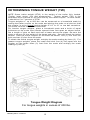
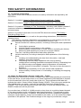
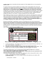
5 STARR
Is a Product of LOAD RITE TRAILERS INC.
Trailer
Operator’s
Manual
IMPORTANT
INFORMATION
ENCLOSED
Please read immediately!
LOAD RITE Trailers, Inc.
265 Lincoln Highway
Fairless Hills, PA 19030
215-949-0500
1
January 2010
1200.01
Table of Contents
Introduction
2
Reporting Safety Defects
3
General Specifications
4-7
Trailer Adjustments
7
Determining Tongue Weight
8-9
AB & AC (Aluminum Bunk) Trailer Set-Up
9 - 10
Operating Information & Pre-Trip Checklist
10
Troubleshooting Chart
11
Attaching Trailer to Tow Vehicle
12 - 14
Operating Your Trailer Equipped with Disc Brakes
15
Maintaining Your Trailer Equipped with Disc Brakes
16
Disc Brake Maintenance Procedure
17– 18
Drum Brake Owners Manual
19 - 24
Tire Safety Information
24 - 37
Vendor Warranty Contact Information
38
The Kenda/Loadstar Worry Free Warranty
?
Purchaser Warranty Registration
?
CONGRATULATIONS!
You have purchased a truly exceptional piece of equipment. Your LOAD RITE
trailer is the finest of its type, incorporating many features as standard
equipment.
Your LOAD RITE trailer is designed and built to give many years of safe and
satisfactory service. In addition to our design efforts, we stand ready to assist
you with any problems or questions you may have regarding the normal
operation and maintenance of your new trailer. Because we are a leading
manufacturer, your dealer has ready access to replacement parts, technical
advice and prompt service.
In order to establish your warranty, the warranty card must be completed and mailed
at the time of purchase. For your records, fill in the same information on the opposite
page. If you have any questions regarding the completion of your trailer warranty
information, your dealer or LOAD RITE Customer Service will be more than happy to
help you. Your product warranty is not in effect until it is registered with LOAD
RITE 'S Warranty Department.
January 2010 1200.01
2
IMPORTANT - PLEASE READ
Please read this manual thoroughly and
completely. A basic understanding of your
trailer is necessary for satisfactory and
SAFE operation.
We reserve the right to change specifications,
designs, or discontinue models at any time
without notice and/or incurring obligations.
Reporting Safety Defects
If you believe that your vehicle has a defect which could cause
a crash or could cause injury or death, you should
immediately inform the National Highway Traffic Safety
Administration (NHTSA) in addition to notifying Load Rite
Trailers, Inc.
If NHTSA receives similar complaints, it may open an
investigation and if it finds that a safety defect exists in a
group of vehicles, it may order a recall and remedy campaign.
However, NHTSA cannot become involved in individual
problems between you, your dealer, or Load Rite Trailers, Inc.
To contact NHTSA. you may either call the Auto Safety
Hotline toll-free at 1-888-327-4236 (TTY: 1-800-424-9153) or
write to: NHTSA, U.S. Department of Transportation, 1200
New Jersey SE, Washington, DC 20590. You can also obtain
other information about motor vehicle safety from the Hotline.
Year
Model
Serial # (VIN)
Dealer
Purchase Date
3
January 2010
1200.01
GENERAL SPECIFICATIONS
LOAD RITE is a registered member of the National Marine Manufacturers Association
(NMMA) and the North American Trailer Manufacturers (NATM) association.
All LOAD RITE trailers are designed and built to meet all US DOT specifications and NMMA
certification.
I. CAPACITY
Imprinted on your trailer certification plate (VIN sticker located on the front left side of your
trailer) is the GVWR capacity. The GVWR represents the combined weight of the trailer
and the load which it was designed to carry. The actual carrying capacity is the GVWR
less the weight of the trailer. Carrying capacity includes the boat, motor, fuel and gear.
If rated capacity is exceeded, the warranty is void.
II. TRAILERING COUPLINGS AND BALLS
Trailer couplings are permanently marked with the following information:
A. The coupler manufacturer's name or initials.
B. Model or Part Number.
C. Ball diameter, for which rating (GVWR) shall not
exceed the gross trailer weight.
Do not use a different size ball than recommended.
CLASS I COUPLER
CLASS II COUPLER
CLASS III COUPLER
CLASS IV COUPLER
2,000#
3,500#
5,000#
7,500#
8,000#
10,000#
13,000#
GVWR
GVWR
GVWR
GVWR
GVWR
GVWR
GVWR
1-7/8" Ball, 3/4" Shank
2" Ball, 3/4" Shank
2" Ball, 1" Shank
2-5/16" Ball, 1" Shank
2" Ball (special application, stamped)
2-5/16" Ball, 1-1/4" Shank
2-5/16" Ball, 1-3/8" Shank
To adjust your standard non-brake coupler (Class I, II and III) to your trailer ball, simply
adjust the nut on the bottom of the coupler. Couplers should be adjusted to a snug fit on
the ball so that the 'play' is removed, but not over-tightened as to create wear. Class IV
couplers and hydraulic brake actuators usually need no adjustments, but may require
periodic greasing via the grease fitting where applicable.
Be sure the ball and hitch ratings match or exceed the gross load (GVWR, trailer weight
and capacity) of your loaded trailer.
III. SAFETY CHAINS
(Towing)
Your trailer is equipped with two towing safety chains or cables. When attaching your
trailer to the tow vehicle, connect each of the safety chains or cables to a separate point
on your hitch per the hitch manufacturer’s instructions.
(Bow)
The bow safety chain (or cable) adjacent to the winch is an added safety feature and must
be used by the operator when towing. After sliding the "S" hook through the bow eye of
the boat, adjust the chain as tight as possible by securing it at the key hole slot on the
winch support bracket. (If trailer has cable, it is non-adjustable)
IV. WIRE COLOR CODE AND LIGHTS
The following wire color code function is used:
White – ground
Brown (2) – taillights, sidemarker lights, and clearance lights for each side of the
trailer
Yellow – left turn and stop light
Green – right turn and stop light
January 2010 1200.01
4
Blue – disc brake free-backing solenoid, to be wired into tow vehicle back up lights
The above wires each correspond with individual circuits on the tow vehicle. Refer to your
dealer, hitch installer, or local automotive repair shop to have the proper vehicle connector
installed.
To avoid trouble with the trailer lighting system, LOAD RITE recommends the following:
A. Make certain the tow vehicle is equipped with a proper harness connection to avoid
overloading circuits.
B. With annual maintenance, remove light lenses and spray metal components with WD40'
or apply a light coating of petroleum jelly.
C. Always carry spare light bulbs.
Tail light bulb - #1157
Marker light bulb - #194
3 light rear bar bulb - #L1895
(DOES NOT APPLY TO LED LIGHTS)
V. WINCHES
LOAD RITE boat trailers are equipped with a hand winch designed for long life and trouble
free launching and loading. Periodically, the gears of your winch should be lubricated
with an all-purpose grease.
Check the winch cable or strap for cuts or frayed fibers at each use. Replace
immediately if any sign of wear is evident.
Be sure to spool the cable or rope across the drum. To extend cable or rope life, avoid a
criss-cross overlap pattern while retrieving.
VI. SECURING THE CARGO FOR TRAILERING
Tie down the boat securely at the stern with either belly type straps, ratcheting tie
downs, or with a good line.
In addition to the winch cable or strap, use the bow safety chain or cable. Again, do not
depend on the winch line alone to secure the boat to the trailer. Be certain that the
bow is resting snugly on the bow rollers. Any loose cargo should be secured within the
boat or to the deck of a flat top trailer.
VII. ALL BOLTS, NUTS, AND FASTENERS
Upon initial trailer inspection, and on a regular basis, check all bolts and nuts for proper
torque.
VIII. BEARINGS AND HUBS
NOTE: Check wheel bearings periodically by the following procedure:
CAUTION - With the trailer connected to the tow vehicle on level ground, set the tow
vehicle parking brake and chock the wheels.
A. Chock the trailer wheel opposite the hub to be removed. Place chocks both in front and
behind the tire.
B. Position the service jack on the frame as near the wheel to be removed as
possible.
C. Rotate the elevated wheel and listen for any noise. If your trailer is equipped with brakes, be
certain that the (drum-style) brake shoes are not dragging. Feel the wheel for any
roughness in its rotation.
D. A quiet and smooth rotation indicates that the bearings are in good shape. If a noise,
grinding sound or roughness in rotation are evident, please contact your dealer for proper
procedure.
E. At this time the wheel bearing adjustment should be checked. At the factory, LOAD RITE
sets the proper torque to maximize bearing life but on occasion it may be necessary to
make an adjustment due to normal wear. To check if bearing adjustment is needed, grip
5
January 2010
1200.01
the edge of the wheel to see if it rocks, or can move laterally. If the wheel moves at all, an
adjustment is necessary.
First, remove the bearing protector or dust cap (refer to the section on bearing protectors in
Section F) and the bearing retainer or cotter pin. Always replace the retainer or cotter pin
with new. DO NOT REUSE! Tighten the spindle nut a little more than "finger
tight" (approximately 20-24 inch pounds). When the nut is tensioned properly the wheel
should rotate easily and have no end play. Reassemble the reverse of disassembling using
a new retainer or cotter pin.
NOTE: Bearing adjustment should be checked after the first 75 miles of
service and every year after.
F. If needed, grease hubs carefully after launch or before storage. Do not add grease when hub
is cold, too much grease could damage brake shoes and hub seal.
Smaller trailers may be built with a steel dust cap or plastic bearing buddy and can only be
properly lubricated by repacking by hand at the end of each season. Bearing protectors can
also be added as an option.
Larger trailers are equipped with a patented lubrication system which incorporates an
internally cored spindle and grease fitting. This allows the hubs to be easily greased without
disassembly, and assures lubrication to the inner bearing. Using a high temperature NLGI #2
wheel bearing grease and a hand-operated grease gun, apply grease after each immersion of a
warm hub into ambient water. This will displace any water introduced during the rapid cooling
process. Lubricate each wheel periodically or before a long trip with a few pumps.
NOTICE: It is required that once a year, each wheel be pulled, and the following items
visually inspected and replaced if necessary: bearings, bearing races, seals and
brake components. Repack with new grease and reassemble using a new cotter
pin.
All work should be performed by a qualified mechanic.
To remove your bearing protector or dust cap, place a piece of wood against the side of it.
Carefully strike the wood with a hammer. Then place the wood on the opposite side, and restrike. Continue this procedure until you have "walked" the protector out of the hub.
To reinstall your bearing protector or dust cap, line it up with your hub, place a block of wood
over the front of the protector and carefully tap the wood with a hammer.
NOTE: All bearing protector caps are designed to fit tightly into the hub. Take extra care in
aligning the protector cap with the hub.
IX. TIRES
To determine the proper tire and rim size and capacity specified for your model, refer to your
Vehicle Identification Number certification plate located on the front left side of your trailer.
Recommended tire air pressure can be found on the certification plate and on the tire
sidewall. Always check tire pressures when cold. Always fill to the maximum rated
cold pressure.
Should the certification plate be damaged or otherwise illegible, the dealer or manufacturer
can determine the proper tire, rim size, and pressure.
When jacking up the trailer to change tires, follow the same procedure as outlined above
when checking hub bearings.
X. BRAKES AND ACTUATOR
Contact local department of motor vehicle authority to determine brake
requirements for the locality in which the trailer is to be registered. For safety, LOAD
RITE recommends brakes on ALL axles where available.
The brake system requires DOT 3 hydraulic brake fluid. Check the actuator reservoir
regularly. Braking components should be thoroughly dry before storage for optimal
service life. CAUTION: Wet brakes operate less efficiently. Use care in operating the
trailer immediately after immersion while launching or loading.
January 2010 1200.01
6
XI. FINISH
After exposure to saltwater, wash the trailer thoroughly with freshwater at the first
convenient opportunity. Galvanized trailers may occasionally show a rust spot or
surface discoloration. If this occurs, touch up with cold galvanizing spray paint. This
product can be obtained through any LOAD RITE dealer, most paint, hardware, or marine
stores.
TRAILER ADJUSTMENTS (Adjustable units only)
LOAD RITE trailers are designed to be fully adjustable. Available models are designed to
adjust to most any variation in width, hull and bow design. Due to tremendous variance in
boat hull designs and the universal nature of LOAD RITE designs, some compromises may
have to be made to achieve the optimum fit.
LOAD RITE trailers are adjusted in a neutral position at the factory. At the time of purchase
the trailer may require adjustments to assure optimum fit of boat to trailer.
Below is a brief list of possible adjustment options for most adjustable trailers:
I. THE WINCH STAND ASSEMBLY
The basic winch stand assembly is designed to allow for two basic adjustments. The first
is for height and the second is for hull position.
To adjust the height, loosen the fasteners clamping the winch support to the near vertical
post. Reposition to the desired height and retighten. Proper height is determined when
the winch line is level with the bow eye of the boat. The winch line should attach to
the bow eye after passing beneath the winch roller.
To adjust for boat hull position, loosen the U-bolts and slide the winch stand along the
tongue, either forward or backward until optimum bow roller to boat hull contact is
achieved.
Hull position relative to the trailer is very important. This position determines where the
boat will sit on the support system. If the winch stand is positioned incorrectly on the
tongue, the rear support system may not be in proper contact with the hull.
II. TONGUE WEIGHT
The axle assemblies, spring or torsion, are attached to the main frame with U-bolts. To
adjust the tongue weight loosen these u-bolts and slide the assemblies forward or
backward as required.
Caution: Be sure not to damage the brake line or wire harness. When complete, be
certain the axle is perfectly perpendicular to the direction of forward travel.
Moving the assemblies forward will decrease tongue weight. Moving the axle rearward will
increase tongue weight.
The actual weight can be determined using a simple scale per the diagram that follows.
Place the scale on a platform so that the tongue is about the same height as the hitch of
the intended tow vehicle. LOAD RITE recommends ideal ball height at 18” to 21” from
ground level to ball centerline. The recommended tongue weight should be the following:
For trailers 2000 lbs. and under, the tongue weight is approximately 7% of
the gross weight (GVWR).
For trailers over 2000 lbs., the tongue weight should equal approximately 5% of the
gross weight (GVWR).
III. ROLLER POSITIONING
Roller trailers offer a great amount of adjustability and can be made to accommodate most
boats.
The cross bars, spanning across the trailer between the main frame rails, offer multiple
height positions on most models. Some models may offer more than one longitudinal
position along the frame. The pivot bars run parallel to the frame members and are
mounted on brackets on top of the cross bars. Pivot bars can be adjusted in or out to suit
hull width and chine location requirements. The roller assemblies, mounted at each end of
7
January 2010
1200.01
DETERMINING TONGUE WEIGHT (TW)
NOTE. Gross trailer weight (GTW) is the weight of the trailer fully loaded.
(Trailer, boat, motor, fuel and accessories). Tongue weight (TW) is the
downward force exerted on the hitch ball by the trailer coupler. In most cases,
it should be 5 to 7 percent of GTW.
Tongue weights of up to 250 Ibs. can be measured on a household scale by
resting the trailer coupler on the scale and placing the scale on a block so that
the coupler is at its normal towing height of 18” to 21” to tow ball centerline.
The trailer must be fully loaded and level.
For heavier tongue weights, place a household scale and a brick of equal
thickness as the scale upon blocks spaced three feet apart as shown below.
Set a length of pipe on each and rest a beam across the pipes. Re -zero the
scale to correct for the weight of the beam and pipe. Securely block the trailer
wheels. Rest the trailer coupler on the beam as shown, one (1) foot from the
brick and two (2) feet from the scale.
To obtain the actual tongue weight, multiply the scale reading by three (3). For
greater tongue weights, place the scale and brick four (4) feet apart rest the
coupler on the beam three (3) feet from the scale and multiply the scale
reading by four (4).
Tongue Weight Diagram
For tongue weights in excess of 200 lbs.
January 2010 1200.01
8
the pivot bar, offer a range of adjustability, as well (on some of the smaller roller model
trailers, the rollers are fixed with no adjustment).
NOTE: It is important to remember that boats with longitudinal strakes or chines should have
the rollers adjusted to run on the flat area of the hull between the strakes or chines.
Also please note that the rollers should be lubricated at least once a year, preferably at the
start of the season, and possibly a second or third time depending on the amount of usage
and water immersion. Use a marine grade white grease to lube the roller hub.
CAUTION - The boat should be removed from the trailer while ALL adjustments are being
performed. Make certain that all fasteners are properly tightened BEFORE the boat is
reloaded onto the trailer.
AB & AC (Aluminum Bunk) Trailer Set-Up
Step #1- Achieving proper Tongue Weight
IMPORTANT NOTICE- PROPER TONGUE WEIGHT OF 5%-6% OF THE GVWR MUST BE
OBTAINED. SINCE THE AXLES ON THE AB TRAILERS ARE ADJUSTABLE, THERE
ARE TWO METHODS TO INCREASE OR REDUCE TONGUE WEIGHT (just below) (also
see ***note at bottom of this set up sheet). MAKE CERTAIN THE BOAT IS LOADED
THE WAY IT WILL BE TOWED (WITH FUEL AND GEAR ON BOARD)
When checking Tongue weight- always weight at the coupler with the trailer in a level
attitude (parallel to the ground).
Method 1) Position the boat on the trailer and move the boat either fore or aft to achieve
proper Tongue weight. The Boat Transom should NEVER overhang the rear Bunk supports
excessively (no more than 8”).
Method 2) Move the Axles. If Boat Positioning (Method 1) will not provide proper Tongue
weight, the Axles can be re-positioned. Never attempt to move Axles with the Boat on the
Trailer! Always mark the Trailer Frames before moving Axles and Fenders so that they are
moved in the exact same amount relative to each other. Re-torque ½” U-Bolts (or Carriage
Bolts) to 45-50 foot pounds when tightening. (Do NOT over torque).
Step #2- Hull set-up
1) Loosen the Target Satellite (or Target Bunk) mounting Bolts and lower the support all the
way down. Leave bolts loose at this time.
2) Adjust Load Bearing Bunk Tube centers (left to right) to fit boat properly. These MUST
be placed as wide as possible so that proper “lateral” hull support is guaranteed. Failure to
do this could result in unsafe towing.
Example – spread Bunks wide in order to assure lateral stability. Avoid all Strakes on hull.
3) Load the boat onto the trailer making sure the trailer is properly attached to the correct
size tow vehicle with the ball latched and Safety Chains or Cables properly secured to the
receiver. Make certain there is adequate Fender clearance and that the boat is not resting
on the Satellite/Target Bunks at this time.
Note: If the Target Satellite/Target Bunks are taking any load at this time, then the main
Bunk Tubes (Load Bearing Bunks) must be raised to a higher adjustment position (these
Target apparatus are NOT designed to support heavy loading at any time).
4) Adjust the winch post location and support head height (so cable is horizontal) to match
the boat bow eye.
5) Snug the Satellite or Target Bunks against the keel (Maximum weight = 200 lbs.)
A hydraulic bottle jack can be used but “don’t overload” these supports or the trailer
frames can be damaged. Tighten all bolts (1/2” straight and U-Bolts to 45 ft. lbs.), (and
check wheel lugs 85-95 ft. lbs.)
6) Hook Winch Cable to bow eye and pull boat “firmly” into roller. (boat’s bow eye must
always be below the Winch Roller). Hook Bow Safety Chain and take up the Chain slack in
the Winch Support keyhole.
*** Load Bearing Bunks (AB Model trailers) are adjustable fore & aft and can help in
achieving proper Tongue weight (rather than moving Axles in most cases).
9
January 2010
1200.01
OPERATING INFORMATION AND PRE-TRIP CHECKLIST
Always tie the boat securely at the bow and stern. Do not depend only on
your winch line to secure your boat.
I. TOWING VEHICLE INFORMATION
Check with your marine dealer to determine the proper towing vehicle capacity for the size
load to be trailered. Some tow vehicles may require over-sized tires, heavy duty
suspension, heavy duty radiator and/or an extra battery. To avoid overloading the lighting
circuits, most vehicles require a trailer towing package. You may also wish to have a
tachometer, vacuum gauge, transmission temperature gauge and/or an engine oil gauge
installed.
II. LAUNCHING YOUR BOAT
Skill and practice will allow proper handling of a boat at the loading ramp.
Stop before reaching the ramp area, without blocking traffic, and remove any tie-downs
securing the boat. Tilt the engine or drive unit up, replace the transom drain plug, etc. It is
recommended that a safety line be attached to the boat so that it can be held in place after
launching. IMPORTANT: Do not disconnect the winch line or bow safety chain until you
are at the water and ready for launch.
Once prepared for launch, back down the ramp to the water. If at all possible, avoid
submerging the trailer's wheel bearings or brakes. This will be unavoidable with most bunk
models.
At this point, check that the safety line is clear and moved to the proper side of the boat for
launching depending on ramp position. Proceed to unfasten the bow safety chain. Securely
hold the winch handle, reverse the winch lock and begin unwinding the line.
Care must be taken at this time to hold the winch handle securely. A free-spinning winch
handle can be very dangerous. If the winch handle begins to free-spin, DO NOT attempt to
stop it by hand.
On an average ramp grade, the boat should gently roll back into the water. If the boat does
not move, unwind 6 to 8 inches of winch line, lock the winch, and give the boat a shove.
Once the boat begins to move, unlock the winch and wind the boat down into the water.
III. LOADING AT THE RAMP
As in launching, prepare for loading before reaching the ramp. Attach the winch line to the
bow eye of the boat and winch the boat onto the trailer. Never allow the winch line to unreel
all the way. Always keep at least 3 turns of the cable around the drum of the winch.
On full roller trailers it is not necessary to have the boat in perfect alignment with the trailer
before loading. Given sufficient time and patience, the boat will automatically align itself as it
is being winched on the trailer. Wind and water conditions can affect alignment. Connect
the bow safety chain as soon as it reaches the bow hook.
Bunk type trailers are designed to load the boat by floating it on to the trailer. They should
be submerged so that only the very front of the bunks are visible above water.
Once the boat is completely on the trailer and the bow safety chain is attached,
pull the trailer away from the ramp area, and out of the way of other boat trailers.
Proceed to fully secure the boat to the trailer before exiting the ramp parking lot.
IV. LOADING MISALIGNMENT
Occasionally a boat will load and be misaligned with the trailer centerline. Below is a partial
list of some possible causes:
A. Trailer rollers are not equally spaced from one side of the trailer to the other.
B. Ramp is slanted from one side to the other. Angling trailer into the water will
sometimes help this situation.
C. Boat does not float level in the water in unloaded position.
D. Occasionally, a boat hull is not sitting squarely on the assembly jig as it is bolted to the
deck. This results in a hull with a slight twist through its longitudinal axis. This situation
normally does not affect the performance characteristics of the craft.
Tidal, wake, or other water current conditions could float the hull off trailer center while
loading.
January 2010 1200.01
10
TROUBLESHOOTING
A. Excessive travel in actuator mechanism:
Possible cause:
Corrective action:
Low fluid in master cylinder reservoir;
Refill master cylinder and bleed system.
air in hydraulic lines.
Leaking primary cup in master cylinder;
Check all components and
ports closed or restricted with dirt; defective
make corrections required.
hoses; leaking check valve fails to hold
hydraulic pressure.
Excessive lining-to-drum clearance.
Adjust brakes or replace linings.
Leaks in hydraulic lines.
Replace defective lines.
B. Pressure build-up in hydraulic system:
Possible cause:
Corrective action:
Master cylinder piston fails to stop,
See Authorized Dealer.
keeping compensating port closed.
See Authorized Dealer.
Contaminated fluid causing rubber
Drain, flush and replace fluid,
cups to swell.
replace cups and rubber hoses.
Hose cylinder ports closed or restricted
Overhaul or replace.
with dirt, or weak return spring.
C. Brake noise
Possible cause:
Corrective action:
Worn or cracked drums or machined
Replace drums.
beyond allowable oversize limits.
Vibration with loose bolts, out-of-
Tighten hub bolts, recondition
round drums.
or replace drums.
Shoe clatter, lining coated with grease.
Correct cause of grease leakage,
reline and grind for proper contact.
Vibration with loose bearing adjustment
Adjust and lubricate bearings or replace.
or rough bearing action.
11
January 2010
1200.01
PROPERLY ATTACHING YOUR TRAILER
TO THE TOW VEHICLE
Mechanical attachment of your trailer to the tow vehicle
Depending
upon
capacity, your trailer is
equipped with a braking
actuator that accepts
either a 2” or 2-5/16"
diameter tow ball with a
centerline 18” to 21”
from the ground. Look
at the side of the
a ctu at o r
for
t his
requirement, and make
certain your tow vehicle
is properly equipped
and set up.
Centerline
Ideal
centerline
range
IMPORTANT SAFETY NOTE
Standard 2” tow balls are rated at 6,000 pounds capacity.
This will safely serve all applications up to 6,000 pounds
GVWR. If your trailer is rated in excess of 6,000 pounds
GVWR, a heavy duty 2” tow ball should be attached to the
actuator at delivery.
If this ball is not present, immediately verify with your
dealer if the 2” heavy-duty ball is mandated for your application. Again, use of the heavy-duty 2” ball applies to all
boat and trailer combinations with a GVWR between 6,000
and 8,000 pounds.
January 2010 1200.01
12
Once you are certain that your tow vehicle
is equipped with a properly sized, rated,
and positioned ball, raise the trailer on the
tongue jack so that the ball of the tow
vehicle can be maneuvered directly
beneath the ball socket of the actuator.
Remove any safety lock pins from the
actuator lever and move the lever to the
forward position. Crank the handle of the
tongue jack and lower the actuator socket
over the tow vehicle ball. Once you are
certain the actuator is fully seated on the
ball, move the latch to the engaged
position and insert the safety pin through
the actuator slider in the hole located
directly behind the ball socket. Continue to
lower the tongue jack to its fully retracted
position. Rotate the jack to its horizontal
position for travel.
Latch
Lever
Forward
Safety
Pin
Actuator - Latch Open
Latch
Lever
Engaged
Latch
Lever
Engaged
Insert Safety
Pin Here
Actuator - Latch Engaged
Attach the safety cables from the trailer
to their proper and respective
attachment points on the tow vehicle.
Make certain the quick-link fasteners
are properly positioned and completely
tightened. Attach the safety brake
activation cable from the actuator to
the tow vehicle adjacent to one of the
quick links.
Quick Link
Attached
Safety Pin
Inserted
Your trailer should now be properly and
safely mechanically attached to your
tow vehicle.
Proceed to electrical
system attachment.
Quick Link
Attached
Emergency
Breakaway
Cable
Attached
Properly Attached Trailer
January 2010 1200.01
13
Electrical system attachment of your trailer to the tow
vehicle
Your trailer is equipped with a six-wire, five-connector wiring harness.
function as follows:
White – ground
The colors
Brown (2) – taillights, sidemarker lights, and clearance lights for each side of the
trailer
Yellow – left turn and stop light
Green – right turn and stop light
Blue – disc brake free-backing solenoid, to be wired into tow vehicle back up
lights
The above wires each correspond with individual circuits on the tow vehicle. Refer to
your dealer, hitch installer, or local automotive repair shop to have the proper vehicle
connector installed.
4 Pin
Vehicle Plug
Solenoid
Pin
5 Pin
Trailer Harness
Solenoid
Wire
Ground
Wire
Solenoid to Reverse
Circuit Connector
Wire to Tow
Vehicle
Reverse
Light Circuit
5 Pin
Trailer to 4 Pin
5 Pin - 6 Wire
Trailer Harness
If your tow vehicle is equipped with a five-wire, four-connector harness, it will be necessary
to retrofit the vehicle with the proper connector. Alternatively, the five-wire four-connector
tow vehicle harness can be used with the six-wire five-connector harness. If the trailer is
equipped with disc brakes, the exposed terminal must be wired to the reverse light circuit
of the tow vehicle for proper brake operation while backing the rig.
January 2010 1200.01
14
OPERATING YOUR
TRAILER EQUIPPED
WITH DISC BRAKES
CHECK FLUID LEVEL
The disc brakes on your trailer function
under the surge principle. As the tow
vehicle brakes are applied, the trailer
pushes, or “surges”, against the tow ball.
This action generates pressure in the
trailer hydraulic system and causes the
brake calipers to squeeze the brake pads
and grip the rotors.
Fill
Cap
Solenoid
Wire
Remove the fill cap and
check the brake fluid level at
each use.
Always top off with DOT 3
brake fluid as needed.
While operating the vehicle in reverse,
pressure is applied to the trailer
hydraulic system as the tow ball pushes
back on the actuator. With the solenoid
wire properly attached to the reverse
Latch
Lever
Slide
Safety
Brake
Cable
Safety Pin
Through Hole
Safety
Pin
light circuit on the tow vehicle and the vehicle
gear selector in reverse position, the actuator
free-reverse solenoid is energized.
When
energized, a third port in the solenoid bleeds all
hydraulic line pressure and fluid flows directly to
the actuator master cylinder reservoir.
The
wheels then rotate freely in reverse.
Latch
Lever
Engaged
Insert Safety
Pin Here
Actuator - Emergency
Backup Engaged
IMPORTANT SAFETY NOTE
Once properly wired, the tow vehicle / trailer rig may be
safely operated on the highway.
In an emergency, the trailer may be jockeyed about the
yard or ramp by any vehicle through utilizing the tethered
lock pin placed in the left side of the actuator inner slide
adjacent to the fixed housing. This hole does not go
through both sides of the slide.
This feature is for
emergency trailer movement only, and is not designed to
supplant use of the solenoid system under roadway
operation.
January 2010 1200.01
15
WARNING - LOAD RITE RECOMMENDS THAT ALL MAINTENANCE BE PERFORMED BY A QUALIFIED MECHANIC.
MAINTAINING YOUR TRAILER EQUIPPED
WITH DISC BRAKES
The disc brakes on your trailer have been engineered for the rigorous duty of a marine
environment. An E-coated rotor and Galv-X coated caliper resist external rust. A stainless
steel caliper piston and brass fittings fight internal corrosion. Stainless steel mounting
bolts and bronze slider bushings promote even wear for season long performance.
Like any mechanical system, the disc brakes on your trailer require periodic inspection and
preventive maintenance. LOAD RITE recommends this service be performed annually
for optimum, reliable system performance. The end of the season is the ideal time
to perform preventive maintenance on your trailer.
Annual Hub and Disc Brake Maintenance Overview
Bleed hydraulic
system.
Inspect pad
thickness and
surface for
irregular wear.
Examine rotor surface
for deep grooves.
Resurface as necessary.
Remove, clean,
inspect, and
lubricate slider
bolts. Clean
bushings.
Remove, clean, inspect, and repack
bearings. Replace
bearings as needed.
Always replace inner
grease seal and outer
retainer.
REGULAR MAINTENANCE NOTE
Add grease easily at any time by removing the rubber
grommet on the bearing cover and exposing the
standard grease fitting.
To prevent inopportune maintenance problems, LOAD
RITE recommends you grease this way after each water
immersion.
January 2010 1200.01
16
WARNING - LOAD RITE RECOMMENDS THAT ALL MAINTENANCE BE PERFORMED BY A QUALIFIED MECHANIC.
IMPORTANT SAFETY NOTE
Never raise a trailer wheel off
the ground for service unless
the trailer is safely attached to
the tow vehicle, and one wheel
on each side of the trailer is
fully chocked.
DISC BRAKE MAINTENANCE PROCEDURE
Work on only one wheel at a time. Begin by removing each wheel and visually
inspecting brake pad thickness. This will
help indicate the amount of remaining pad
Inner Pad Thickness
life. Examine the faces of each rotor for
Mounting
signs of uneven wear. Run a fingernail
Bolt
across each face. If this test indicates
ridges or other imperfections exist in the
rotor face, you may want to consider
Bleeder
having the rotors resurfaced. Resurface
Screw
the rotors in pairs and always replace the
pads when resurfacing the rotors.
Remove the bolts securing the caliper to
the mounting bracket. Inspect the face of
the brake pad in the same way you
inspected the rotor. Replace the pads if
Mounting
Bolt
there are any surface irregularities or if the
pads have 3/16” or less material from the
surface to the most shallow rivet. If one
pad needs replacement, always replace
all of the pads on the same axle. Always
resurface the rotors when replacing the
pads.
Bleeder Screw
Secure the caliper to the frame and out of
the way of the rotor with a zip tie or
bungee cord. Do not allow the caliper to
hang from the brake hose!
Remove the outer bearing protector.
Remove the locking mechanism and large
outer nut from the spindle.
Mounting
Bolt
Bushing
January 2010 1200.01
17
Carefully remove the rotor (or hub) from
the spindle taking care to prevent the
outer bearing from falling out of the
rotor (or hub).
Remove the outer
bearing and set aside. Invert the rotor
(or hub) so the inner seal is visible.
Remove the inner seal and discard.
Replace with a new seal at reassembly.
Remove the inner bearing and set
aside.
SERVICE NOTE
Always replace these items at
each hub service! Retainer
design may vary by model.
Outer
Retainer
Wipe each bearing with a clean cloth.
Be careful to remove all excess and
contaminated lubricant.
Wipe the
spindle clean with a clean cloth.
Examine all bearing and spindle
surfaces for discoloration or pitting. If
evidence of either, replace all affected
components. In the case of evidence of
water contamination, replace all
bearings and seals immediately.
Inner Seal
Cotter Pin
Retainer
Pack each bearing with high temperature lithium based NLGI #2 wheel bearing grease. Reassemble in the reverse
order of disassembly. Remember to install a new seal and a new spindle nut locking
device.
DISC BRAKES
Reinstall the caliper over the rotor and
secure with the stainless mounting
Inspect bearing
bolts.
Apply blue Loctite to the
rollers for pitting,
threads of the slider bolts. Torque to
cracking, and
20 lb. ft. if coarse threads, 35 - 40 lb.
discoloration.
ft. if fine thread.
Install the wheel. While rotating the
wheel, torque the spindle nut to 20 lb.
ft. Loosen ¼ turn and retighten by
hand until snug. Securely fit the
spindle nut locking device.
Inspect inner surface
of bearing race for
pitting, cracking, and
discoloration.
Torque the wheel lugs to 80 – 95 lb. ft.
Repeat all of the above for each
wheel on your trailer.
BLEED YOUR BRAKES
Bleeding the brake hydraulic system at each caliper should be part of
annual trailer maintenance. Brake fluid absorbs moisture and becomes
ineffective at converting hydraulic pressure to braking action. It is possible
for the brakes to become ineffective or even lock during operation if the fluid
is not serviced annually.
January 2010 1200.01
18
19
January 2010
1200.01
January 2010 1200.01
20
21
January 2010
1200.01
January 2010 1200.01
22
23
January 2010
1200.01
January 2010 1200.01
24
TIRE SAFETY INFORMATION
1.1. Tire Safety Information
This portion of the User’s Manual contains tire safety information as required by 49
CFR 575.6.
Section 2.1 contains “Steps for Determining Correct Load Limit - Trailer”.
Section 2.2 contains “Steps for Determining Correct Load Limit – Tow Vehicle”.
Section 2.3 contains a Glossary of Tire Terminology, including “cold inflation pressure”,
“maximum inflation pressure”, “recommended inflation pressure”, and other nontechnical terms.
Section 2.4 contains information from the NHTSA brochure entitled “Tire Safety –
Everything Rides On It”.
This brochure This brochure, as well as the preceding subsections, describes the
following items;
Tire labeling, including a description and explanation of each marking on the tires,
and information about the DOT Tire Identification Number (TIN).
Recommended tire inflation pressure, including a description and explanation
of:
A. Cold inflation pressure.
B. Vehicle Placard and location on the vehicle.
C. Adverse safety consequences of under inflation (including tire failure).
D. Measuring and adjusting air pressure for proper inflation.
Tire Care, including maintenance and safety practices.
Vehicle load limits, including a description and explanation of the following
items:
A. Locating and understanding the load limit information, total load
capacity, and cargo capacity.
B. Calculating total and cargo capacities with varying seating
configurations including quantitative examples showing / illustrating how
the vehicles cargo and luggage capacity decreases as combined
number and size of occupants’ increases. This item is also discussed in
Section 3.
C. Determining compatibility of tire and vehicle load capabilities.
D. Adverse safety consequences of overloading on handling and stopping
on tires.
1.2. Steps for Determining Correct Load Limit – Trailer
Determining the load limits of a trailer includes more than understanding the load limits
of the tires alone. On all trailers there is a Federal certification/VIN label that is located
on the forward half of the left (road) side of the unit. This certification/VIN label will
indicate the trailer’s Gross Vehicle Weight Rating (GVWR). This is the most weight the
fully loaded trailer can weigh. It will also provide the Gross Axle Weight Rating
(GAWR). This is the most a particular axle can weigh. If there are multiple axles, the
GAWR of each axle will be provided.
If your trailer has a GVWR of 10,000 pounds or less, there is a vehicle placard located
in the same location as the certification label described above. This placard provides
tire and loading information. In addition, this placard will show a statement regarding
maximum cargo capacity. Cargo can be added to the trailer, up to the maximum weight
specified on the placard. The combined weight of the cargo is provided as a single
25
January 2010
1200.01
number. In any case, remember: the total weight of a fully loaded trailer can not exceed the
stated GVWR.
For trailers with living quarters installed, the weight of water and propane also need to be
considered. The weight of fully filled propane containers is considered part of the weight of the
trailer before it is loaded with cargo, and is not considered part of the disposable cargo load.
Water however, is a disposable cargo weight and is treated as such. If there is a fresh water
storage tank of 100 gallons, this tank when filled would weigh about 800 pounds. If more cargo
is being transported, water can be off-loaded to keep the total amount of cargo added to the
vehicle within the limits of the GVWR so as not to overload the vehicle. Understanding this
flexibility will allow you, the owner, to make choices that fit your travel needs.
When loading your cargo, be sure it is distributed evenly to prevent overloading front to back and
side to side. Heavy items should be placed low and as close to the axle positions as reasonable.
Too many items on one side may overload a tire. The best way to know the actual weight of the
vehicle is to weigh it at a public scale. Talk to your dealer to discuss the weighing methods
needed to capture the various weights related to the trailer. This would include the weight empty
or unloaded, weights per axle, wheel, hitch or king-pin, and total weight.
Excessive loads and/or underinflation cause tire overloading and, as a result, abnormal tire
flexing occurs. This situation can generate an excessive amount of heat within the tire. Excessive
heat may lead to tire failure. It is the air pressure that enables a tire to support the load, so proper
inflation is critical. The proper air pressure may be found on the certification/VIN label and/or on
the Tire Placard. This value should never exceed the maximum cold inflation pressure stamped
on the tire.
1.2.1. Trailers 10,000 Pounds GVWR or Less
Tire and Loading Information Placard – Figure 1-1
1.
2.
3.
Locate the statement, “The weight of cargo should never exceed XXX kg or XXX lbs.,” on
your vehicle’s placard. See figure 1-1.
This figure equals the available amount of cargo and luggage load capacity.
Determine the combined weight of luggage and cargo being loaded on the vehicle. That
weight may not safely exceed the available cargo and luggage load capacity.
The trailer’s placard refers to the Tire Information Placard attached adjacent to or near the
trailer’s VIN (Certification) label at the left front of the trailer.
1.2.2. Trailers Over 10,000 Pounds GVWR (Note: These trailers are not required to have
a tire information placard on the vehicle)
Determine the empty weight of your trailer by weighing the trailer using a public scale or other
means. This step does not have to be repeated.
Locate the GVWR (Gross Vehicle Weight Rating) of the trailer on your trailer’s VIN
(Certification) label.
January 2010 1200.01
26
Subtract the empty weight of your trailer from the GVWR stated on the VIN label. That weight
is the maximum available cargo capacity of the trailer and may not be safely exceeded.
1.3. Steps for Determining Correct Load Limit – Tow Vehicle
1. Locate the statement, “The combined weight of occupants and cargo should never
exceed XXX lbs.,” on your vehicle’s placard.
2. Determine the combined weight of the driver and passengers who will be riding in your
vehicle.
3. Subtract the combined weight of the driver and passengers from XXX kilograms or XXX
pounds.
4. The resulting figure equals the available amount of cargo and luggage capacity. For
example, if the “XXX” amount equals 1400 lbs. and there will be five 150 lb. passengers
in your vehicle, the amount of available cargo and luggage capacity is 650 lbs. (1400-750
(5 x 150) = 650 lbs.).
5. Determine the combined weight of luggage and cargo being loaded on the vehicle. That
weight may not safely exceed the available cargo and luggage capacity calculated in
Step # 4.
6. If your vehicle will be towing a trailer, load from your trailer will be transferred to your
vehicle. Consult the tow vehicle’s manual to determine how this weight transfer reduces
the available cargo and luggage capacity of your vehicle.
1.4. Glossary Of Tire Terminology
Accessory weight
The combined weight (in excess of those standard items which may be replaced) of automatic
transmission, power steering, power brakes, power windows, power seats, radio and heater, to
the extent that these items are available as factory-installed equipment (whether installed or
not).
Bead
The part of the tire that is made of steel wires, wrapped or reinforced by ply cords and that is
shaped to fit the rim.
Bead separation
This is the breakdown of the bond between components in the bead.
Bias ply tire
A pneumatic tire in which the ply cords that extend to the beads are laid at alternate angles
substantially less than 90 degrees to the centerline of the tread.
Carcass
The tire structure, except tread and sidewall rubber which, when inflated, bears the load.
Chunking
The breaking away of pieces of the tread or sidewall.
Cold inflation pressure
The pressure in the tire before you drive.
Cord
The strands forming the plies in the tire.
Cord separation
The parting of cords from adjacent rubber compounds.
Cracking
Any parting within the tread, sidewall, or inner liner of the tire extending to cord material.
CT
A pneumatic tire with an inverted flange tire and rim system in which the rim is designed with
rim flanges pointed radially inward and the tire is designed to fit on the underside of the rim in
27
January 2010
1200.01
a manner that encloses the rim flanges inside the air cavity of the tire.
Curb weight
The weight of a motor vehicle with standard equipment including the maximum capacity of
fuel, oil, and coolant, and, if so equipped, air conditioning and additional weight optional
engine.
Extra load tire
A tire designed to operate at higher loads and at higher inflation pressures than the
corresponding standard tire.
Groove
The space between two adjacent tread ribs.
Gross Axle Weight Rating
The maximum weight that any axle can support, as published on the Certification / VIN label
on the front left side of the trailer. Actual weight determined by weighing each axle on a public
scale, with the trailer attached to the towing vehicle.
Gross Vehicle Weight Rating
The maximum weight of the fully loaded trailer, as published on the Certification / VIN label.
Actual weight determined by weighing trailer on a public scale, without being attached to the
towing vehicle.
Hitch Weight
The downward force exerted on the hitch ball by the trailer coupler.
Innerliner
The layer(s) forming the inside surface of a tubeless tire that contains the inflating medium
within the tire.
Innerliner separation
The parting of the innerliner from cord material in the carcass.
Intended outboard sidewall
The sidewall that contains a white-wall, bears white lettering or bears manufacturer, brand,
and/or model name molding that is higher or deeper than the same molding on the other
sidewall of the tire or the outward facing sidewall of an asymmetrical tire that has a particular
side that must always face outward when mounted on a vehicle.
Light truck (LT) tire
A tire designated by its manufacturer as primarily intended for use on lightweight trucks or
multipurpose passenger vehicles.
Load rating
The maximum load that a tire is rated to carry for a given inflation pressure.
Maximum load rating
The load rating for a tire at the maximum permissible inflation pressure for that tire.
Maximum permissible inflation pressure
The maximum cold inflation pressure to which a tire may be inflated.
Maximum loaded vehicle weight
The sum of curb weight, accessory weight, vehicle capacity weight, and production options
weight.
Measuring rim
January 2010 1200.01
28
The rim on which a tire is fitted for physical dimension requirements.
Pin Weight
The downward force applied to the 5th wheel or gooseneck ball, by the trailer kingpin or
gooseneck coupler.
Non-pneumatic rim
A mechanical device which, when a non-pneumatic tire assembly incorporates a wheel,
supports the tire, and attaches, either integrally or separably, to the wheel center member and
upon which the tire is attached.
Non-pneumatic spare tire assembly
A non-pneumatic tire assembly intended for temporary use in place of one of the pneumatic
tires and rims that are fitted to a passenger car in compliance with the requirements of this
standard.
Non-pneumatic tire
A mechanical device which transmits, either directly or through a wheel or wheel center
member, the vertical load and tractive forces from the roadway to the vehicle, generates the
tractive forces that provide the directional control of the vehicle and does not rely on the
containment of any gas or fluid for providing those functions.
Non-pneumatic tire assembly
A non-pneumatic tire, alone or in combination with a wheel or wheel center member, which
can be mounted on a vehicle.
Normal occupant weight
This means 68 kilograms (150 lbs.) times the number of occupants specified in the second
column of Table I of 49 CFR 571.110.
Occupant distribution
The distribution of occupants in a vehicle as specified in the third column of Table I of 49 CFR
571.110.
Open splice
Any parting at any junction of tread, sidewall, or innerliner that extends to cord material.
Outer diameter
The overall diameter of an inflated new tire.
Overall width
The linear distance between the exteriors of the sidewalls of an inflated tire, including
elevations due to labeling, decorations, or protective bands or ribs.
Ply
A layer of rubber-coated parallel cords.
Ply separation
A parting of rubber compound between adjacent plies.
Pneumatic tire
A mechanical device made of rubber, chemicals, fabric and steel or other materials, that, when
mounted on an automotive wheel, provides the traction and contains the gas or fluid that
sustains the load.
Production options weight
The combined weight of those installed regular production options weighing over 2.3 kilograms
(5 lbs.) in excess of those standard items which they replace, not previously considered in curb
29
January 2010
1200.01
weight or accessory weight, including heavy duty brakes, ride levelers, roof rack, heavy duty
battery, and special trim.
Radial ply tire
A pneumatic tire in which the ply cords that extend to the beads are laid at substantially 90
degrees to the centerline of the tread.
Recommended inflation pressure
This is the inflation pressure provided by the vehicle manufacturer on the Tire Information label
and on the Certification / VIN tag.
Reinforced tire
A tire designed to operate at higher loads and at higher inflation pressures than the
corresponding standard tire.
Rim
A metal support for a tire or a tire and tube assembly upon which the tire beads are seated.
Rim diameter
This means the nominal diameter of the bead seat.
Rim size designation
This means the rim diameter and width.
Rim type designation
This means the industry of manufacturer’s designation for a rim by style or code.
Rim width
This means the nominal distance between rim flanges.
Section width
The linear distance between the exteriors of the sidewalls of an inflated tire, excluding
elevations due to labeling, decoration, or protective bands.
Sidewall
That portion of a tire between the tread and bead.
Sidewall separation
The parting of the rubber compound from the cord material in the sidewall.
Special Trailer (ST) tire
The "ST" is an indication the tire is for trailer use only.
Test rim
The rim on which a tire is fitted for testing, and may be any rim listed as appropriate for use
with that tire.
Tread
That portion of a tire that comes into contact with the road.
Tread rib
A tread section running circumferentially around a tire.
Tread separation
Pulling away of the tread from the tire carcass.
Treadwear indicators (TWI)
The projections within the principal grooves designed to give a visual indication of the degrees
January 2010 1200.01
30
of wear of the tread.
Vehicle capacity weight
The rated cargo and luggage load plus 68 kilograms (150 lbs.) times the vehicle’s designated
seating capacity.
Vehicle maximum load on the tire
The load on an individual tire that is determined by distributing to each axle its share of the
maximum loaded vehicle weight and dividing by two.
Vehicle normal load on the tire
The load on an individual tire that is determined by distributing to each axle its share of the
curb weight, accessory weight, and normal occupant weight (distributed in accordance with
Table I of CRF 49 571.110) and dividing by 2.
Weather side
The surface area of the rim not covered by the inflated tire.
Wheel center member
In the case of a non-pneumatic tire assembly incorporating a wheel, a mechanical device
which attaches, either integrally or separably, to the non-pneumatic rim and provides the
connection between the non-pneumatic rim and the vehicle; or, in the case of a non-pneumatic
tire assembly not incorporating a wheel, a mechanical device which attaches, either integrally
or separably, to the non-pneumatic tire and provides the connection between tire and the
vehicle.
Wheel-holding fixture
The fixture used to hold the wheel and tire assembly securely during testing.
1.5. Tire Safety - Everything Rides On It
The National Traffic Safety Administration (NHTSA) has published a brochure (DOT HS 809
361) that discusses all aspects of Tire Safety, as required by CFR 575.6. This brochure is
reproduced in part below. It can be obtained and downloaded from NHTSA, free of charge,
from the following web site:
http://www.nhtsa.dot.gov/cars/rules/TireSafety/ridesonit/tires_index.html
Studies of tire safety show that maintaining proper tire pressure, observing tire and vehicle
load limits (not carrying more weight in your vehicle than your tires or vehicle can safely
handle), avoiding road hazards, and inspecting tires for cuts, slashes, and other irregularities
are the most important things you can do to avoid tire failure, such as tread separation or
blowout and flat tires. These actions, along with other care and maintenance activities, can
also:
Improve vehicle handling
Help protect you and others from avoidable breakdowns and accidents
Improve fuel economy
Increase the life of your tires.
This booklet presents a comprehensive overview of tire safety, including information on the
following topics:
Basic tire maintenance
Uniform Tire Quality Grading System
Fundamental characteristics of tires
Tire safety tips.
Use this information to make tire safety a regular part of your vehicle maintenance routine.
31
January 2010
1200.01
Recognize that the time you spend is minimal compared with the inconvenience and safety
consequences of a flat tire or other tire failure.
1.6. Safety First–Basic Tire Maintenance
Properly maintained tires improve the steering, stopping, traction, and load-carrying capability of
your vehicle. Underinflated tires and overloaded vehicles are a major cause of tire failure.
Therefore, as mentioned above, to avoid flat tires and other types of tire failure, you should
maintain proper tire pressure, observe tire and vehicle load limits, avoid road hazards, and
regularly inspect your tires.
1.6.1. Finding Your Vehicle's Recommended Tire Pressure and Load Limits
Tire information placards and vehicle certification labels contain information on tires and load
limits. These labels indicate the vehicle manufacturer's information including:
Recommended tire size
Recommended tire inflation pressure
Vehicle capacity weight (VCW–the maximum occupant and cargo weight a vehicle is
designed to carry)
Front and rear gross axle weight ratings (GAWR– the maximum weight the axle systems
are designed to carry).
Both placards and certification labels are permanently attached to the trailer near the left
front.
1.6.2. Understanding Tire Pressure and Load Limits
Tire inflation pressure is the level of air in the tire that provides it with load-carrying capacity
and affects the overall performance of the vehicle. The tire inflation pressure is a number that
indicates the amount of air pressure– measured in pounds per square inch (psi)–a tire requires
to be properly inflated. (You will also find this number on the vehicle information placard
expressed in kilopascals (kpa), which is the metric measure used internationally.)
Manufacturers of passenger vehicles and light trucks determine this number based on the
vehicle's design load limit, that is, the greatest amount of weight a vehicle can safely carry and
the vehicle's tire size. The proper tire pressure for your vehicle is referred to as the
"recommended cold inflation pressure." (As you will read below, it is difficult to obtain the
recommended tire pressure if your tires are not cold.)
Because tires are designed to be used on more than one type of vehicle, tire manufacturers
list the "maximum permissible inflation pressure" on the tire sidewall. This number is the
greatest amount of air pressure that should ever be put in the tire under normal driving
conditions.
1.6.3. Checking Tire Pressure
It is important to check your vehicle's tire pressure at least once a month for the following
reasons:
Most tires may naturally lose air over time.
Tires can lose air suddenly if you drive over a pothole or other object or if you strike
the curb when parking.
With radial tires, it is usually not possible to determine underinflation by visual
inspection.
For convenience, purchase a tire pressure gauge to keep in your vehicle. Gauges can be
purchased at tire dealerships, auto supply stores, and other retail outlets.
The recommended tire inflation pressure that vehicle manufacturers provide reflects the proper
psi when a tire is cold. The term cold does not relate to the outside temperature. Rather, a cold
tire is one that has not been driven on for at least three hours. When you drive, your tires get
warmer, causing the air pressure within them to increase. Therefore, to get an accurate tire
pressure reading, you must measure tire pressure when the tires are cold or compensate for
the extra pressure in warm tires.
January 2010 1200.01
32
1.6.4. Steps for Maintaining Proper Tire Pressure
Step 1: Locate the recommended tire pressure on the vehicle's tire information
placard, certification label, or in the owner's manual.
Step 2: Record the tire pressure of all tires.
Step 3: If the tire pressure is too high in any of the tires, slowly release air by gently
pressing on the tire valve stem with the edge of your tire gauge until you get to the
correct pressure.
Step 4: If the tire pressure is too low, note the difference between the measured tire
pressure and the correct tire pressure. These "missing" pounds of pressure are what
you will need to add.
Step 5: At a service station, add the missing pounds of air pressure to each tire that
is underinflated.
Step 6: Check all the tires to make sure they have the same air pressure (except in
cases in which the front and rear tires are supposed to have different amounts of
pressure).
If you have been driving your vehicle and think that a tire is underinflated, fill it to the
recommended cold inflation pressure indicated on your vehicle's tire information placard or
certification label. While your tire may still be slightly underinflated due to the extra pounds of
pressure in the warm tire, it is safer to drive with air pressure that is slightly lower than the vehicle
manufacturer's recommended cold inflation pressure than to drive with a significantly
underinflated tire. Since this is a temporary fix, don't forget to recheck and adjust the tire's
pressure when you can obtain a cold reading.
1.6.5. Tire Size
To maintain tire safety, purchase new tires that are the same size as the vehicle's original tires or
another size recommended by the manufacturer. Look at the tire information placard, the owner's
manual, or the sidewall of the tire you are replacing to find this information. If you have any doubt
about the correct size to choose, consult with the tire dealer.
1.6.6. Tire Tread
The tire tread provides the gripping action and traction that prevent your vehicle from slipping or
sliding, especially when the road is wet or icy. In general, tires are not safe and should be
replaced when the tread is worn down to 1/16 of an inch. Tires have built-in treadwear indicators
that let you know when it is time to replace your tires. These indicators are raised sections
spaced intermittently in the bottom of the tread grooves. When they appear "even" with the
outside of the tread, it is time to replace your tires. Another method for checking tread depth is to
place a penny in the tread with Lincoln's head upside down and facing you. If you can see the top
of Lincoln's head, you are ready for new tires.
1.6.7. Tire Balance and Wheel Alignment
To avoid vibration or shaking of the vehicle when a tire rotates, the tire must be properly
balanced. This balance is achieved by positioning weights on the wheel to counterbalance
heavy spots on the wheel-and-tire assembly. A wheel alignment adjusts the angles of the
wheels so that they are positioned correctly relative to the vehicle's frame. This adjustment
maximizes the life of your tires. These adjustments require special equipment and should be
performed by a qualified technician.
1.6.8. Tire Repair
The proper repair of a punctured tire requires a plug for the hole and a patch for the area inside
the tire that surrounds the puncture hole. Punctures through the tread can be repaired if they are
not too large, but punctures to the sidewall should not be repaired. Tires must be removed from
the rim to be properly inspected before being plugged and patched.
1.6.9. Tire Fundamentals
Federal law requires tire manufacturers to place standardized information on the sidewall of all
tires. This information identifies and describes the fundamental characteristics of the tire and also
provides a tire identification number for safety standard certification and in case of a recall.
1.6.9.1. Information on Passenger Vehicle Tires
Please refer to the diagram below.
33
January 2010
1200.01
P
The "P" indicates the tire is for passenger vehicles.
Next number
This three-digit number gives the width in millimeters of the tire from sidewall edge to sidewall
edge. In general, the larger the number, the wider the tire.
Next number
This two-digit number, known as the aspect ratio, gives the tire's ratio of height to width.
Numbers of 70 or lower indicate a short sidewall for improved steering response and better
overall handling on dry pavement.
R
The "R" stands for radial. Radial ply construction of tires has been the industry standard for the
past 20 years.
Next number
This two-digit number is the wheel or rim diameter in inches. If you change your wheel size,
you will have to purchase new tires to match the new wheel diameter.
Next number
This two- or three-digit number is the tire's load index. It is a measurement of how much weight
each tire can support. You may find this information in your owner's manual. If not, contact a
local tire dealer. Note: You may not find this information on all tires because it is not required
by law.
M+S
The "M+S" or "M/S" indicates that the tire has some mud and snow capability. Most radial tires
have these markings; hence, they have some mud and snow capability.
January 2010 1200.01
34
Letter Rating
Speed Rating
Q
99 mph
R
106 mph
S
112 mph
T
118 mph
U
124 mph
H
130 mph
V
149 mph
W
168* mph
Y
186* mph
Speed Rating
The speed rating denotes the speed at which a tire is designed to be driven for extended
periods of time. The ratings range from 99 miles per hour (mph) to 186 mph. These ratings are
listed below. Note: You may not find this information on all tires because it is not required by
law.
* For tires with a maximum speed capability over 149 mph, tire manufacturers sometimes use
the letters ZR. For those with a maximum speed capability over 186 mph, tire manufacturers
always use the letters ZR.
U.S. DOT Tire Identification Number
This begins with the letters "DOT" and indicates that the tire meets all federal standards. The
next two numbers or letters are the plant code where it was manufactured, and the last four
numbers represent the week and year the tire was built. For example, the numbers 3197
means the 31st week of 1997. The other numbers are marketing codes used at the
manufacturer's discretion. This information is used to contact consumers if a tire defect
requires a recall.
Tire Ply Composition and Materials Used
The number of plies indicates the number of layers of rubber-coated fabric in the tire. In
general, the greater the number of plies, the more weight a tire can support. Tire
manufacturers also must indicate the materials in the tire, which include steel, nylon, polyester,
and others.
Maximum Load Rating
This number indicates the maximum load in kilograms and pounds that can be carried by the
tire.
Maximum Permissible Inflation Pressure
This number is the greatest amount of air pressure that should ever be put in the tire under
normal driving conditions.
35
January 2010
1200.01
1.6.9.2. UTQGS Information
Treadwear Number
This number indicates the tire's wear rate. The higher the treadwear number is, the longer it
should take for the tread to wear down. For example, a tire graded 400 should last twice as
long as a tire graded 200.
Traction Letter
This letter indicates a tire's ability to stop on wet pavement. A higher graded tire should allow
you to stop your car on wet roads in a shorter distance than a tire with a lower grade. Traction
is graded from highest to lowest as "AA","A", "B", and "C".
Temperature Letter
This letter indicates a tire's resistance to heat. The temperature grade is for a tire that is
inflated properly and not overloaded. Excessive speed, underinflation or excessive loading,
either separately or in combination, can cause heat build-up and possible tire failure. From
highest to lowest, a tire's resistance to heat is graded as "A", "B", or "C".
1.6.9.3. Additional Information on Light Truck Tires
Please refer to the following diagram.
Tires for light trucks have other markings besides those found on the sidewalls of passenger
tires.
LT - The "LT" indicates the tire is for light trucks or trailers.
ST - An "ST" is an indication the tire is for trailer use only.
Max. Load Dual kg (lbs) at kPa (psi) Cold
This information indicates the maximum load and tire pressure when the tire is used as a dual,
that is, when four tires are put on each rear axle (a total of six or more tires on the vehicle).
Max. Load Single kg (lbs) at kPa (psi) Cold
This information indicates the maximum load and tire pressure when the tire is used as a
single.
January 2010 1200.01
36
Load Range
This information identifies the tire's load-carrying capabilities and its inflation limits.
1.7. Tire Safety Tips
Preventing Tire Damage
Slow down if you have to go over a pothole or other object in the road.
Do not run over curbs or other foreign objects in the roadway, and try not to strike the
curb when parking.
Tire Safety Checklist
Check tire pressure regularly (at least once a month), including the spare.
Inspect tires for uneven wear patterns on the tread, cracks, foreign objects, or other signs
of wear or trauma.
Remove bits of glass and foreign objects wedged in the tread.
Make sure your tire valves have valve caps.
Check tire pressure before going on a long trip.
Do not overload your vehicle. Check the Tire Information and Loading Placard or User’s
Manual for the maximum recommended load for the vehicle.
37
January 2010
1200.01
WARRANTY INFORMATION
If you experience any difficulties or defects with parts of the trailer, please look for
the manufacturer’s name on the part and contact them directly. The following is a
list of Load Rite’s current vendors from whom parts are purchased:
PART
DESCRIPTION
VENDOR
C.H. Yates Rubber Corp.
PHONE NUMBER
Rubber Roller
1-508-674-3378
Cequent Electrical Products Wire Harness
1-800-786-7968
Cequent Trailer Products
Plastic Fenders
1-715-693-1700
Dutton-Lainson
Tongue Jack, Couplers,
Winches
1-402-462-4141
Kenda / LOADSTAR
Tires
1-800-225-4714
Petersen
Incandescent Lights, LED
Lights
1-800-821-3490
Peerless Chain
Safety Chain
1-800-533-8056
Reliable Tool & Machine
Torsion Axle
1-260-347-4000
Tie Down Engineering
Torsion Axle, Brakes (disc &
drum), Actuator, Safety Cable, 1-800-241-1806
Aluminum Fenders
Titan International
Actuator
January 2010 1200.01
1-800-872-2327
38
LOAD RITE Trailers, Inc.
265 Lincoln Highway
Fairless Hills, PA 19030
215-949-0500
39
January 2010
1200.01