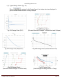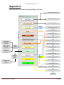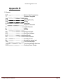
1
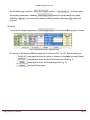
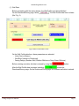
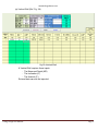
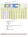
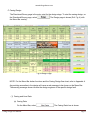
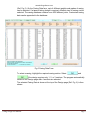
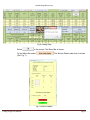
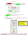
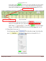
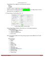
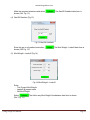
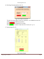
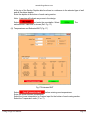
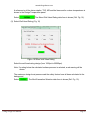
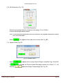
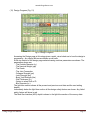
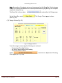
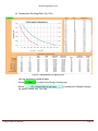
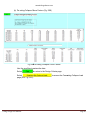
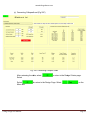
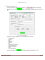
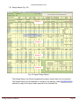
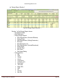
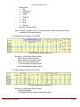
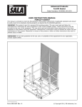
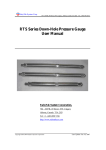
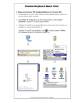
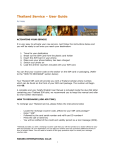
www.drillingsoftware.com
Drillingsoftware
Casing Design User Manual
1. Introduction
Working Stress Design (WSD) loads are evaluated throughout the entire length of the casing from
the Well Head to the Casing Shoe. True Vertical Depth (TVD) is now fully linked to Vertical Well
Geometry or Directional Well Geometry. Accurate TVD’s are used for precise Burst, Collapse and
Tensile load calculations. User defined Custom Casing Specifications can also be incorporated into
the design. The program is designed to take the user through a logical sequence to achieve the
optimum casing design.
2. Operation
A. Menu
Fig. 1 Menu
Casing Design User Manual
Page 1
www.drillingsoftware.com
On the Menu page, selecting
the program parameters. Selecting
Selecting
program.
and the
buttons explain
shows the Directional/Survey page.
shows the contact details of drillingsoftware. Selecting
closes the
B. Set-up
To set-up the design program select
, The Directional/Survey page is shown
Fig.2 Directional/Survey Page Buttons
On the top of the Directional/Survey
/Survey page are four buttons (Ref. Fig. 2A).
). These buttons are:
selecting this shows an option to increase or decrease the magnification
-
selecting
electing this shows the Well Profile data form (Ref. Fig. 3)
3
-
selecting this shows th
the Design page (Ref. Fig. 4)
-
prints the Survey page.
Casing Design User Manual
Page 2
www.drillingsoftware.com
(1) Well Data
Before proceeding with the casing design, the Well Profile must be established.
On the Directional/Survey page, select
. The Well Profile data form is shown
(Ref. Fig. 3).
Fig.3 Well Profile Data Form
On the Well Profile data form, these parameters are selected:
- Units (Feet or Meters)
- Well Bore (Vertical or Directional)
- Casing Design (Onshore Well, Shallow Offshore or Deep Water Offshore).
Before entering new data, old data is cleared by using the
button.
After the Well Profile data is entered, selecting
shows the
Directional/Survey page. On the Directional/Survey page the selected well data is entered.
Casing Design User Manual
Page 3
www.drillingsoftware.com
(a) Vertical Well (Ref. Fig. 3A)
Fig.3A Vertical Well
A Vertical Well requires these inputs:
- The Measured Depth (MD)
- The Inclination (0˚)
- The Azimuth (0˚).
External data can also be imported.
Casing Design User Manual
Page 4
www.drillingsoftware.com
(b) Directional Well (Fig. 3B)
Fig.3B Directional Well
A Directional Well requires these inputs:
- The Survey Depth
- The MD
- The Inclination
- The Azimuth.
When this data is entered, the following is automatically calculated:
- TVD
- Sub Sea TVD (TVD SS)
- N/-S
- E/-W
- DLS
- Closure.
External data can also be imported.
Casing Design User Manual
Page 5
www.drillingsoftware.com
C. Casing Design
The Directional/Survey page is the entry point for the design stage. To start the casing design, on
the Directional/Survey page, select
the Menu Bar overlay..
. The Design page is shown (Ref. Fig. 4) with
Fig.4 Design Page
NOTE: For the Menu Bar button functions and the Casing Design flow chart, refer to Appendix A.
Any existing anomalies in the design will cause a red message to be shown on the Menu Bar.
The warning message shown informs the design engineer of the specific design fault.
(1) Casing and Liner Data
(a) Casing Data
On the Menu Bar, select
Casing Design User Manual
. The Casing Data form is shown
Page 6
www.drillingsoftware.com
(Ref. Fig. 5). On the Casing Data form, up to 4 different weights and grades of casing
can be selected. If a tapered string design is required, different sizes of casing can be
selected. The casing database contains over 4000 different joints. Customized casing
data can be appended to the database.
Fig.5 Casing Data Form
To select a casing, highlight the required casing section. Select
and
if the design requires only 1, 2, or 3 sections. The program automatically
returns to the Design page after 4 sections are selected.
The selected Casing Data is shown at the top of the Design page (Ref. Fig. 6) is then
shown.
Casing Design User Manual
Page 7
www.drillingsoftware.com
Fig.6 Casing Data
Select
on the prompt. The Menu Bar is shown.
On the Menu Bar select
(Ref. Fig. 7).
. The Section Depths data form is shown
Fig.7 Section Depths
Casing Design User Manual
Page 8
www.drillingsoftware.com
Select
to clear any existing data. After entering the depths of each
casing section in the section panels, select
prompt is shown (Ref. Fig 8).
. The Update Charts
Fig.8 Update Charts
Selecting
If
, returns the program to the Design page (Ref. Fig. 4).
is selected, refer to Para. 2. C. (14).
(b) Liner Data
On the Design Page (Ref. Fig. 4), select
panel is shown (Ref Fig. 9).
. A Design for a Liner
Use the existing upper section of
the casing and enter the TOL as
the bottom of section 1.
Enter up to 3 liner sections below
the existing cemented casing
Fig.9 Design for a Liner
Casing Design User Manual
Page 9
www.drillingsoftware.com
On the panel, select
. The liner(s) can now be selected in the same manner
as selecting casing data [Ref. Para. 2. C.(1) (a)]. After selection, the design page is
shown with the selected
elected liner data shown at the top of the design page (Ref. Fig. 10).
Previous cemented casing
Up to 3 liner sections can be used
Fig.10 Liner Data
If the sections for a liner have been selected, and
was selected on the
Design for a Liner panel (Ref. Fig. 9), the prompt
is
, then select
on the Liner Design
shown. Select
Dialogue.. The Liner Data is now shown at the top of the Design page (Ref. Fig.
F 10).
(2) Design Safety Factors (Fig. 11)
On the Design page, select
select
. The Menu Bar is shown. On the Menu Bar,
Bar
. The Design Factors data form is shown (Ref. Fig. 11).
Fig.11 Design Factors
Casing Design User Manual
Page 10
www.drillingsoftware.com
On the Design Factors data form, the following are selected:
- Burst
- Collapse
- Tension.
An option to enter Custom Safety Factors is also available
Make the required selections and select
Setup data form is shown (Ref. Fig. 12).
. The Casing Design Condition
(3) Casing Design Condition Setup (Fig. 12)
12 Casing Design Condition Setup
Fig.12
On the Casing Design Condition Setup data form,, the following are selected:
- Design Conditions:
• Salt Water Gradient (Offshore)
• Onshore or Offshore
• Drilling or Producing Case
• Axial Tension.
Note: The updated version of the Casing Design program includes Bi-axial
Bi
and Tri-axial
calculations.
- String Selection:
• Structural
• Jetted
• Driven
• Conductor
• Surface 1 Csg
• Surface 2 Csg
• Scab Liner
• Intermediate Csg
• Intermediate Liner/Drlg Liner
• Production Csg
• Production Liner
• Tieback String.
Casing Design User Manual
Page 11
www.drillingsoftware.com
Make the required selections and select
shown (Ref. Fig. 13).
. The Gas/Oil Gradient data form is
(4) Gas/Oil Gradient (Fig.13)
Fig.13 Gas/Oil Gradient
Enter the gas or oil gradient and select
shown (Ref Fig. 14).
. The Mud Weight –Leakoff data form is
(5) Mud Weight – Leakoff (Fig 14)
Fig.14 Mud Weight – Leakoff
Enter:
- The Present Mud Weight
- Leakoff @ present shoe
- Old Mud Weight.
Select
(Ref. Fig. 15).
Casing Design User Manual
. The Add in any Mud Weight Overbalance data form is shown
Page 12
www.drillingsoftware.com
(6) Mud Weight Overbalance Option ((Fig. 15)
Fig
Fig.15 Mud Weight Overbalance
This data form gives an option to enter any overbalance. This is deducted from the mud
weight to give a more accurate pore pressure.
Select
Select
if not required for the design.
. The Section De
Depths
pths data form is shown (Ref. Fig. 16).
16
(7) Section Depths (Fig. 16)
Fig.16 Section Depths
Casing Design User Manual
Page 13
www.drillingsoftware.com
At the top of the Section Depths data form there is a reference to the selected type of well
and all the datum depths.
Enter the depths at the bottom of each casing section.
Note: A warning will indicate any errors in the design.
Select
and enter the new depths. Select
estimated BHT data form is shown (Ref. Fig. 13)
. The
(8) Temperatures and Estimated BHT (Fig. 17)
Fig.17 Estimated BHT
Select
before entering new temperatures.
Enter the known ambient temperature.
Select the Linear Interpolation or Custom Input for the bottom of each casing section.
Select the Temperature units (˚C or ˚F).
Casing Design User Manual
Page 14
www.drillingsoftware.com
A reference to all the datum depths, TVD, MD and the linear and/or custom temperatures is
shown in the Design Temperature panel.
Select
. The Select Well Head Rating data form is shown (Ref. Fig. 18).
(9) Select Well Head Rating (Fig. 18)
Figure 18 Select Well Head Rating
Select the well head rating design (from 1000psi to 20000psi).
Note: If a rating below the calculated surface pressure is selected, a red warning will be
shown.
The maximum design burst pressure and the safety factors have all been calculated in the
background.
Select
Casing Design User Manual
. The Mud Evacuation Selection data form is shown (Ref. Fig. 19).
Page 15
www.drillingsoftware.com
(10) Mud Evacuation (Fig. 19))
Fig.19 Mud Evacuation
Select the percentage of mud evacuation for the design. 0% to 100% or
a custom percentage can be entered.
Note: If a producing well design was previously selected, the program automatically selects
100% mud evacuation.
Select
. The
he Update Ch
Charts data form is shown (Ref. Fig. 20)
20
(11) Update Charts (Fig. 20)
Fig. 20 Update Charts
Select
If
Selecting
Casing Design User Manual
to update all the D
Design Report/ Design Charts (Ref. Figs. 24 and 25).
is selected
selected, the
he Printout Header Data page is shown. Go
G to Para. 2. C. (14).
shows the D
Design Progress page (Ref. Fig. 21)
21
Page 16
www.drillingsoftware.com
(12) Design Progress (Fig. 21)
Fig.21 Design Progress
Accessing the Design page at this stage gives a quick, visual check as to how the design is
progressing. Any design failures are shown as red cells.
At the top section of the design page selected casing sections parameters are shown. The
parameters shown are:
- The Outside Diameter (in.)
- The Nominal Weight (ppf)
- The Grade
- The Joint Connection
- Collapse Strength (psi)
- Joint Strength (psi)
- Body Yield Strength (lbs)
- Wall Thickness (in.)
- Option to select Drift or ID
- Box Diameter (in.).
The light blue section shows all the present and previous mud data and the next setting
depths.
Immediately below the light blue section all the design safety factors are shown. Any failed
safety factors will show in red.
The Mud Gas Interface (MGI) depth is shown in the light blue section of the survey data.
Casing Design User Manual
Page 17
www.drillingsoftware.com
Note: Any section of the design set
set-up
up can be accessed via the Menu Bar. Quick changes
to any of the design parameters can be accomplished without going through the complete
sequential design set-up.
up.
The Menu Bar is shown when
On the Menu Bar, select
(Ref. Fig. 22).
is selected on the Design page.
. The Design Criteria
eria page is shown
(13) Design Criteria (Fig. 22)
Fig.22 Design Criteria
From the Design Criteria Page the following are reviewed :
- Temperature De-rating
rating Factors
- De-rating
rating Factors due to Axial Loading
- Cementing Safety Factors
Factors.
Select
Effect page (Ref. Fig. 22A
22A).
Casing Design User Manual
to access the Temperature De-rating
Page 18
www.drillingsoftware.com
(a) Temperature De-rating Effect (Fig. 22A)
Fig.22A Temperature De-rating Effect
Use the scroll bar to review all data.
Select
to return to the Design Criteria page.
Select
De-rating Factors (Ref. Fig. 22B).
Casing Design User Manual
to access the Collapse Strength
Page 19
www.drillingsoftware.com
(b) De-rating
rating Collapse Curve Factors (Fig. 22B)
Fig.22B De-rating Collapse Curve Factors
Use the scroll bar to review the data.
Select
to return to the Design Criteria page.
Select
page (Ref. Fig. 22C).
).
Casing Design User Manual
to access the Cementing Collapse Load
Page 20
www.drillingsoftware.com
(c) Cementing Collapse Load (Fig 22C)
Fig. 22C Cementing Collapse Load
After reviewing the data, select
Select
Select
Menu Bar
Casing Design User Manual
to return
urn to the Design Criteria page.
to return to the Design Page
Page. Select
on the
Page 21
www.drillingsoftware.com
(14) Printout Header (Fig. 23)
The Printout Header
eader is accessed from either the
page (Ref. Fig. 4) or the
20).
button on the Design
button on the Update Charts prompts
prompt (Fig. 8 and Fig.
Fig. 23 Printout Header
The Printout Header is used to input the well particulars. These are:
- Well Name/No.
- Location
- Rig
- RKB Elev
- RKB-WH
- AFE
- Coordinates (Lat/Long)
- Design Prepared By
- Operating Company
- Date
- Risk Classification.
Enter the data. Select
Casing Design User Manual
. The Design Report is shown (Ref. Fig. 24).
Page 22
www.drillingsoftware.com
(15) Design Report (Fig. 24)
Section 1
(16) D
e
s
i
g
n
Section 2
R
e
p
o
r
t
Section 3
F
i
g
.
2
4
)
Section 4
Fig. 24 Typical Design Report
The Design Report is a full and comprehensive report, broken down into four sections.
The Design Report can be exported or e-mailed to the operator. When
selected, a copy of the report is also exported to the local well file.
Casing Design User Manual
is
Page 23
www.drillingsoftware.com
(a) Design Report Section 1
T
h
e
Fig.24A Design Report Section 1
Section 1 of the Design Report shows:
- The Report Header
- Well Particulars
- Casing Design Report:
• Well Classification (Onshore/Offshore)
• Casing String
• Well Classification (Drilling/Production)
• SW Grad
• Mud Evacuation (%)
• Well Classification (Vertical/Directional)
• Water Depth
• Gas/Oil Grad.
• Risk Class
• Well Head Rating.
- Casing Section:
• MD
• Size
• Weight
• Grade
• Connection
• Collapse (psi)
• Burst (psi)
• Joint (lbs)
• Body (lbs)
• Wall
• ID
• Drift ID
• Box OD.
Casing Design User Manual
Page 24
www.drillingsoftware.com
- Survey Data:
• MD
• Inclination (˚)
• Azimuth (˚)
• TVD
• TVD SS
• N/-S
• E/-W
• DLS
• Closure
- Mud Gas Interface (MGI).
Note: The MGI is linked to the % of mud evacuation and is indicated in all four
sections of the Design Report.
(b) Design Report: Section 2 (Fig. 24B)
Fig.24B Design Report Section 2
Section 2 of the Design Report shows:
- MD at the top of each section
- MD at the bottom of each section
- TVD at the top of each section
- TVD at the bottom of each section
- All calculated design safety factors.
(c) Design Report: Section 3 (Fig. 20C)
Fig.24C Design Report Section 3
Section 3 of the Design Report shows:
- All Rated Strengths
- All De-rated Strengths due to temperature effect.
Casing Design User Manual
Page 25
www.drillingsoftware.com
(d) Design Report: Section 4 (Fig. 24D)
Fig.24D Design Report: Section 4
Section 4 of the Design Report shows:
- All De-rated strengths due to axial loading
- Cementing safety factors.
When
is selected in the Design Report, all the design parameters and safety
factors are linked and updated. These include:
- De-rated Loads
• Burst
• Collapse
• De-rated Tension
• Pressure ratings
• Temperature De-rated Yields.
In addition, all Design Charts are constructed (Ref. Fig. 25).
Casing Design User Manual
Page 26
www.drillingsoftware.com
(17) Typical Design Charts (Fig. 25)
When
is selected in the Design Report, the design charts are displayed to
give an instant visual indication for easy analysis
Fig. 25A Design Chart (DLS)
Fig.25C Design Chart (Departure)
Fig.25E Design Chart
(De-rated Tensile Strength vs Tensile Load)
Casing Design User Manual
Fig. 25B Design Chart
(De-rated Burst and Collapse vs Rated Burst and Collapse)
Fig.25D Design Chart (Vertical Section View)
Fig.25F Design Chart
(Yield Strength De-rating Factors vs Temp).
Page 27
www.drillingsoftware.com
Appendix A
1. Menu Bar Button Functions and Casing Design Flow Chart
Casing Data (Figs. 5 and 6)
Liner Data (Figs. 5 and 10)
Section Depths (Fig. 7)
Design
Steps
Design Factors (Fig. 11)
Casing Design (Fig. 12)
Gas/Oil Gradient (Fig .13)
Mud Weight-Leakoff (Fig. 14)
Mud Weight Overbalance (Fig. 15)
Temperature
De-rating Effect
(Fig. 22A)
De-rating Collapse
Curve Factors
(Fig. 22B)
Section Depths (Figs. 7 and 16)
Design
Criteria
(Fig. 22)
Temperatures (Fig. 17)
Cementing
Collapse Load
(Fig. 22C)
Well Head Rating (Fig. 18)
% Mud Evacuation (Fig. 19)
Directional/
Survey
(Fig. 2)
Yes
NO
Update Charts (Fig. 20)
Design Progress (Fig. 21)
Well Profile Data
Input
(Fig. 3)
Printout Header (Fig. 23)
Print/Export
Design Report (Fig. 24)
Design Charts (Fig. 25)
Print/Export
Casing Design User Manual
Page 28
www.drillingsoftware.com
Appendix B
1. Glossary
BHT
˚C
Csg
DLS
Drlg
E/-W
˚F
ID
in
lbs
MD
MGI
N/-S
OD
ppf
psi
TVD
TVD SS
WSD
Casing Design User Manual
Bottom Hole Temperature
Degrees Centigrade
Casing
Dog Leg Severity
Drilling
East/West
Degrees Fahrenheit
Inside Diameter
inches
pounds
Measured Depth
Mud Gas Interface
North/South
Outside Diameter
pounds per foot
pounds per square inch
True Vertical Depth
True Vertical Depth Sub Sea
Working Stress Design
Page 29