1
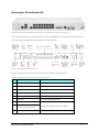
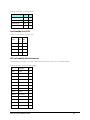
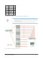
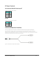
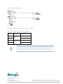
NetStream IDU – NetStream RM IDU-NetStream RM IDU-NetStream RM Package Contents The IDU-NetStream RM package contains: • IDU-NetStream RM - see Figure 1 below. • 19” rack mounting kit - see Figure 2 below • Two DC power plugs for power cables - see Figure 3 below Figure 1: IDU-NetStream RM Package contents - the IDU-NetStream RM, Ethernet only Figure 2:IDU-NetStream RM Package contents - the IDU-NetStream RM, 16 E1/T1 ports Figure 3: IDU-NetStream RM Package contents - the mounting kit and DC power plugs Netronics IDU-NetStream RM 2 Mounting the IDU-NetStream RM Figure 4: IDU-NetStream RM Package contents - the IDU-NetStream RM, 16 E1/T1 ports IDU-NetStream RMs are all rack mountable, as shown in Figure 5. A front panel keyed schematic of a rack mounted IDU-NetStream RM is shown in the figure below. Figure 5: IDU-NetStream RM front panel Further description of the keyed items in Figure 5 is shown in Table 1 below: Table 1: Components of an IDU-NetStream RM front panel Key Label Remarks A Indicator LEDs See Figure 6. B ODU Port RJ-45 connector, see Table 4. C LAN RJ45Ports Ethernet, RJ-45 connector, see Table 5. D LAN SFP Port See below. E Alarm Ports Standard DB25 female connector, see Table 8. F Label indent Place for adhesive identification labels. G Primary 3 pin Power Connector H Secondary 3 pin Power Connector I Grounding Lug Netronics IDU-NetStream RM Standard 3 pins in line power connector, see Table 9. Use the lug supplied. 3 J Rack mounting holes K Detachable Rack mounting brackets L 0, 4, 8 or 16 E1/T1 Ports See Table 6. M Standby Port Hot Standby ready: HSB cable socket, see Table 7. The Indicator LEDs (Item A in Table 1 above) are shown in more detail below: Figure 6: IDU-NetStream RM Front Panel LEDs The IDU-NetStream DT Front Panel LEDS look like this and are functionally the same as the IDUNetStream RM LEDs. Figure 7: IDU-NetStream DT Front Panel LEDs The purpose of the LEDs is shown in Table 2 below: Table 2: IDU-NetStream RM Front Panel LEDs Name IDU Color Function Green IDU operational Blinking Green During power-up only Red Failure Blinking Orange During power-up; continues if ODU fails to load IDU firmware. Also, when using an IDU-NetStream RM to replace a PoE device in which case all other LEDs off. ODU AIR I/F Green ODU-to-IDU communication link is operating Red ODU-to-IDU communication link is disrupted Green Wireless link is synchronized Orange During installation mode; also signals software mismatch on some identical ODUs Red Wireless link lost synchronization Netronics IDU-NetStream RM 4 SVC HSS Green E1 or T1 line is synchronized Orange Alarm detected at the opposite site interface; Normal or LOSS Blinking Orange Local or remote loopback Red Alarm detected at this site interface Off Ethernet only IDU or E1/T1 not configured See supplementary Table 3 following. Hot Standby Mode - for use with Trunks only Link State Green Primary Active Blinking Green Secondary Not active Red Primary Not active Orange Secondary Active Off Off HSM not activated Hot Standby Mode - For use with Ethernet only in a 1+1 Ring application) Link State STBY Green Blinking Green Red Hardware ready Orange Off Table 3: IDU-NetStream RM and New Style IDU-NetStream DT Front Panel LEDs for HSS Color Function Green This ODU is HSS master, generating signal, and HSS Sync is OK Blinking Green This ODU is a HSS client and in Sync Red HSS not operational due to improper signal detection. This ODU is not transmitting HSS is operational. One of the following conditions apply: Orange • • This ODU is a master that is generating signals and detecting signals This ODU is a master that is generating signals but detected improper signals • This ODU is a client “Continue Tx” but is not detecting signals • This ODU is a client “Disable Tx” and is detecting signals from multiple sources All orange cases transmit. Off HSS is not activated Disconnection between ODU and IDU Netronics IDU-NetStream RM 5 To mount an IDU-NetStream RM (The keys refer to Figure 5): 1. Attach the rack mounting brackets (K) to the IDU. 2. Bolt the IDU into an empty slot in the rack, ensuring that it sits securely. 3. Ground the IDU to the rack using grounding lug I. The IDU should be left permanently grounded. Instead of using the rack mounting brackets, the IDU may be rail mounted using the four screw holes on each of its sides. Netronics IDU-NetStream RM 6 Technical Specifications This section contains technical specifications of IDU-NetStream RM appearing in this User Manual. They are correct at the date of publication, but are intended for general background only. The latest authoritative and most up to date technical specifications are available as Data Sheets obtainable from Netronics Customer Service. In any event, Netronics reserves the right to change these specifications without notice. IDU-NetStream RM TDM Interface Number of ports 16, 8, 4 ports or no TDM ports. Max ports usable by NetStream 16 (model dependent) Type E1/T1 configurable by Link Manager Framing Unframed (transparent) Timing Independent timing per port, Tx and Rx Connector RJ-45 Standards Compliance ITU-T G.703, G.826 Line Code E1: HDB3 @ 2.048 Mbps, T1: B8ZS/AMI @ 1.544 Mbps Latency Configurable 5-20 ms (default 8 ms) Impedance E1: 120Ω, balanced, T1: 100Ω, balanced Jitter & Wander According to ITU-T G.823, G.824 Jitter Buffer Jitter Buffer configuration enabling a latency from 5ms to 16ms for interference immunity confront Clock Recovery Resolution 0.05ppb Clock stability 20ppm as clock master (crucial for wander requirements of cellular operators) Monitored Hot Standby Supported Ethernet ports Number of Ports 2 Type 10/100/1000BaseT with Auto-Negotiation (IEEE 802.3u). Framing/Coding IEEE 802.3 Connector RJ-45 Line Impedance 100Ω SFP Interface 1 port, Type: Fast Ethernet VLAN Support Transparent Netronics IDU-NetStream RM 7 Maximum Frame Size 2048 Bytes Bridge Layer 2, self-learning of up to 2047 MAC addresses (IEEE 802.1Q), hub/Bridge selectable mode Latency 3 ms Dry Contact Alarms Dry Contact Alarms 4 Inputs + 4 Outputs; Configurable by the Link Manager ODU Interface Connector RJ-45 Cable Outdoor CAT-5e cable; Maximum cable length: 100 m Mechanical Style 1U 19” Rack mounted Dimensions 43.6 cm (W) x 21 cm (D) x 4.4 cm (H) Weight 1.5 kg/3.3 lbs Power Power Consumption With NetStream ODU < 35 W Alone <10 W Power Feeding Options Dual feeding, -20 to -60 VDC, AC Power Adapters available Environmental Operating Temperatures 0°C - 50°C / 32°F - 122°F Humidity 90% non-condensing Storage -20° to 70°C / --4°F to 158°F Humidity 95% Safety TUV UL 60950-1, CAN/CSA C22.2 60950-1 EN/IEC 60950-1 EMC FCC CFR47 Class B, Part 15, Subpart B ETSI EN 300 386, EN 301 489-4, EN 301 489-1 CAN/CSA-CEI/IEC CISPR 22 Class B AS/NZS CISPR 22:2006 Class B Netronics IDU-NetStream RM 8 Wiring Specifications ODU-IDU Cable The ODU-IDU cable is shielded/outdoor class CAT 5e, 4 twisted-pair 24 AWG terminated with RJ-45 connectors on both ends. A cable gland on the ODU side provides hermetic sealing. The following table shows the connector pin out: Table 4: ODU-IDU RJ-45 Connector Pin out Function Color IDU ODU Ethernet (RxN) White/Green 1 1 Ethernet (RxT) Green 2 2 Ethernet (TxT) White/Orange 3 3 Ethernet (TxN) Orange 6 6 Power (+) Blue 4 4 Power (+) White/Blue 5 5 Power ( ) White/Brown 7 7 Power ( ) Brown 8 8 User Port Connectors LAN Port The LAN 10/100BaseT interface terminates in an 8-pin RJ-45 connector, wired in accordance to Table 5. Table 5: Fast Ethernet Connector Pinout Function Signal Pin Transmit Data (positive) TD (+) 1 Transmit Data (negative) TD (–) 2 Receive Data (positive) RD (+) 3 Receive Data (negative) RD (–) 6 Trunk Ports - E1/T1 RJ45 Connector The E1/T1 interfaces terminate in 8-pin RJ-45 connectors, as shown in Table 6 below: Netronics IDU-NetStream RM 9 Table 6: Trunk Ports - E1/T1 RJ45Pinout Function Signal Pin Transmit Data Tip TxTip 1 Transmit Data Ring TxRing 2 Receive Data Tip RxTip 4 Receive Data Ring RxRing 5 Hot Standby Port RJ-11 Table 7: Hot Standby RJ-11 Port Pinout Pin Side A Pin Side B HSB out 1 2 HSB in 2 1 Ground 3 3 Ground 4 4 Signal IDU (all models) Alarm Connector The IDU Alarm interface is a 25 pin D type female connector. Its pin out is listed in Table 8. Table 8: IDU Alarm Connector (Dry Contact) I/O Description Pin Input 1 Positive 14 Input 1 Negative 15 Input 2 Positive 16 Input 2 Negative 17 Input 3 Positive 18 Input 3 Negative 19 Input 4 Positive 20 Input 4 Negative 21 Output 1 Normally Open 1 Output 1 Common 2 Output 1 Normally Closed 3 Output 2 Normally Open 4 Output 2 Common 5 Netronics IDU-NetStream RM 10 Output 2 Normally Closed 6 Output 3 Normally Open 7 Output 3 Common 8 Output 3 Normally Closed 9 Output 4 Normally Open 10 Output 4 Common 11 Output 4 Normally Closed 12 The figure below, shows how to connect external input and output alarms. • • Use an external current limit resistor to limit the current at the output relays to 1 Amp. Such resistor is not required if the equipment connected to the IDU supports current limiting to 1 Amp. The voltage of the input alarm must be within the range of -10 to -50 VDC.. Figure 8: Example for connecting the alarm connector Netronics IDU-NetStream RM 11 DC Power Terminals IDU-NetStream RM & IDU-NetStream DT Table 9: Terminal Block 3-pin -48 VDC Function Pin + Right Chassis Center – Left DC PoE Table 10: Terminal Block 2-pin -48 VDC Function Pin + Right – Left Unbalanced Mode for E1 Interface You may configure the E1 interface to unbalanced mode (75 ohm) using the Link Manager. Figure 9 shows an adapter cable for connecting devices with balanced E1 interface to the user equipment with unbalanced E1 interface. The Y splitter cable includes one RJ-45 balanced connector (left) and two unbalances BNC coaxial connectors (right). Figure 9: Unbalanced E1 adapter cable (Y Splitter) Netronics IDU-NetStream RM 12 Figure 10 provides a schematic: Figure 10: Unbalanced E1 adapter cable (Y Splitter) - schematic Table 11: E1 Y Splitter Pin out for Unbalanced Mode BNC Connector 2 (NGND) 1 (Center) 2 (NGND) 1 (Center) Color Code RJ-45 Connector Pin 1, 4, 7, 8 Red 2 1, 4, 7, 8 Green 5 The Y-splitter cable cannot be used as a balanced to unbalanced converter. The cable merely provides a physical interface conversion without any impedance matching. Some devices automatically detect cable insertion and change the impedance internally. 600-15 Allstate Parkway, Markham Ontario, Canada Tel: +1 (905) 415 4585 Email: [email protected] Netronics-networks.com