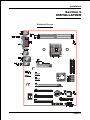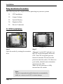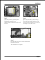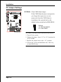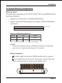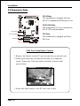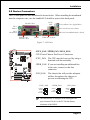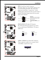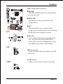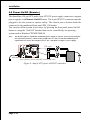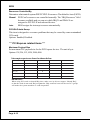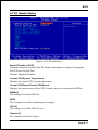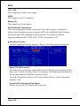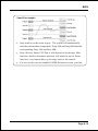
1
User’s Manual nVIDIA nForce 4 4X mainboard for AMD nForce4 Socket 754 based Athlon 64 processor TRADEMARK All products and company names are trademarks or registered trademarks of their respective holders. These specifications are subject to change without notice. 60000028NP710 Manual Revision 1.0 April 29, 2005 DISCLAIMER OF WARRANTIES: THERE ARE NO WARRANTIES WHICH EXTEND BEYOND THE DESCRIPTION ON THE FACE OF THE MANUFACTURER LIMITED WARRANTY. THE MANUFACTURER EXPRESSLY EXCLUDES ALL OTHER WARRANTIES, EXPRESS OR IMPLIED, REGARDING ITS PRODUCTS; INCLUDING ANY IMPLIED WARRANTIES OF MERCHANTABILITY, FITNESS FOR A PARTICULAR PURPOSE OR NONINFRINGEMENT. THIS DISCLAIMER OF WARRANTIES SHALL APPLY TO THE EXTENT ALLOWED UNDER LOCAL LAWS IN THE COUNTRY PURCHASED IN WHICH LOCAL LAWS DO NOT ALLOW OR LIMIT THE EXCLUSION OF THE IMPLIED WARRANTIES. ii Table of Contents Page Section 1 Introduction Package Contents ...................................................... 1- 1 Mainboard Features ................................................... 1- 2 System Block Diagram ............................................... 1- 5 Section 2 Specification Mainboard Specification ............................................ 2- 1 Section 3 Installation Mainboard Layout ..................................................... 3- 1 Easy Installation Procedure ....................................... 3- 2 CPU Insertion ............................................................. 3- 2 Jumper Settings .......................................................... 3- 4 System Memory Configuration .................................. 3- 5 Expansion Slots .......................................................... 3- 6 Device Connectors..................................................... 3- 7 Power-On/Off (Remote) .............................................. 3- 12 Section 4 BIOS Setup Main Menu ................................................................ 4- 1 Standard CMOS Setup ............................................... 4- 2 Advanced BIOS Features .......................................... 4- 3 Advanced Chipset Features ...................................... 4- 6 Integrated Peripherals ................................................ 4- 10 Power Management Setup ......................................... 4- 14 PNP/PCI/PCI-E Configuration .................................... 4- 15 PC Health Status ........................................................ 4- 17 Power BIOS Features ................................................. 4- 20 Defaults Menu ........................................................... 4- 22 iii Supervisor/User Password Setting ............................ 4- 23 Exit Selecting .............................................................. 4- 24 Section 5 RAID Configuration Introduction ............................................................... 5- 1 NVidia RAID Features ................................................. 5- 3 Enable RAID Function ............................................... 5- 4 Section 6 Driver Installation Easy Driver Installation .............................................. 6- 1 Realtek Sound Manager Quick User guide ................ 6- 2 Appendix Appendix A Update Your System BIOS ......................................... A- 1 Appendix B NVidia RAID BIOS Utility ............................................ B- 1 iv Introduction Section 1 INTRODUCTION 1-1 Package Contents Optional Items Contents H. Extra USB2.0 port cable A. Mainboard B. User’s manual If you need the optional item, please contact your dealer for assistance. C. Floppy drive cable D. HDD drive cable E. CD (drivers and utilities) F. I/O Shield G .S-ATA data and power cable USER’S MANUAL D B A E C F H G Page 1-1 Introduction 1-2 Mainboard Features Brief Introduction AthlonTM 64 Processor The AMD AthlonTM 64 processor family is designed to support performance desktop. It provides a high performance HyperTransportTM link to I/O, as well as a single 64-bit high-performance DDR memory controller. For more information about all the new features AthlonTM 64 Processor deliver, check out the AMD website at http://www.amd.com Chipset The board is designed with NVIDIA nForce4 4X chipset, featuring performance and stability with the most innovative technology and features, including the world’s first and only native Gigabit Ethernet interface and hardware-optimized Firewall security solution. For more details about the NVIDIA nForce4, please visit the NVIDIA Web site at http://www.nvidia.com. PCI-Express (PCI-E) Next generation peripheral interface to succeed to current PCI bus for the next decade. With smaller slot size and 250MB/sec (PCI-E*1) or 4GB/sec(PCI-E*16) maximum transfer, PCI-Express overcomes PCI bus bottleneck. Hardware Monitoring Hardware monitoring enables you to monitor various aspects of the system operation and status. This includes CPU temperature, voltage and fan speed in RPMs. 10/100 LAN This mainboard is mounted with a ethernet LAN PHY. It allows the mainboard to connect to a local area network by means of a network hub. Serial ATA Support Serial ATA, an evolutionary replacement for Parallel ATA IDE storage interface. Increases the peak data transfer speed up to 150MB/sec and allows future enhancements to the computing platform. Page 1-2 Introduction S-ATA RAID RAID function available on chipset S-ATA ports. USB2.0 A popular USB standard for plugging in peripherals with up to 480Mbps transfer speed while maintaining backward compatibility with older USB1.1 device. 6ch Mainboard is equipped with 6 channel of audio to support Dolby Digital 5.1 audio for DVD-playback. The onboard audio jacks can be configured for normal 2 channel mode or 6 channel mode. AMD Cool'n'QuietTM Technology AMD's Cool'n'QuietTM Technology lowers CPU operating voltage when the system is in idle mode. This helps to reduce heat dissipation and in effect lowers the fan speed to noise from your PC. Page 1-3 Introduction Special Features BIOS Features: & Magic Health Reports your system hardware status for every boot-up to help detect faults early. Monitor hardware status including CPU temperature, CPU/Memory/ Chipset voltage, fan RPM speed for chassis fan, CPU fan & Power supply fan. & EZ-Boot Simply press “ESC” to select your bootable device. No more hassle to search the BIOS menu, change and re-start. & PowerBIOS Supporting a full range of overclocking setting via BIOS. Various adjustable feature include FSB/Chipset/Memory voltage tweaking. H/W Features: & QuickSPDIF On board SPDIF-out connector for quick connection to multi-channel speakers. Not only removes cable cluttering but also delivers loss-free digital audio to let you enjoy DVD movies and games with crystal clear sound. Page 1-4 Introduction 1-3 System Block Diagram Page 1-5 Introduction Page 1-6 Specification Section 2 SPECIFICATION Mainboard Specification Processor Support Socket-754 based AMD Athlon-64/Sempron processor up to 3700+ with 1.6GTs Hyper Transport Chipset nVidia nForce4 4X Chipset Main Memory Two 184-pin DDR SDRAM DIMM sockets Support single-sided or double-sided 2.5v DDR-266/333/400 DIMMs in 128/256/512Mb technologies Supports up to 2GB memory size Expansion Slots Three PCI connectors compliant with PCI v2.3 Two PCI-E x1 connectors compliant with PCI Express 1.0a One PCI-E x16 connectors compliant with PCI Express 1.0a USB Ten USB connectors compliant with USB2.0 from embedded USB controller (4 connectors at rear panel) P-ATA IDE Two IDE interface (up to 4 IDE devices) with UDMA-33, ATA-66/100/133 support from embedded IDE controller S-ATA RAID Four S-ATA ports with up to 150MB/s bandwidth support RAID 0, 1, 0+1, JBOD Page 2-1 Specification LAN 10/100Mbps Ethernet from Realtek RTL8201 LAN PHY Audio 6 channel audio from onboard ALC655 AC’97 v2.3 compliant CODEC - Support Aux-In, CD-In - Coaxial S/PDIF-out available on rear panel - Support Jack detection for fool-proof audio device installation - Rear panel audio jacks configuration Audio Jack Color 2 ch an n el 6 ch an n el Light Blue Line-in Rear stereo-out Lime Line-out Front stereo-out Pink Mic-in Center&Subwoofer I/O Onboard Fintek LPC bus I/O controller Legacy peripheral interface for PS/2 keyboard & mouse, FDD, Parallel, Serial, and IrDA (v1.0 compliant) Support Hardware Monitoring for fan speed monitoring, CPU/System temperature Intelligent fan speed control for quiet operation BIOS Flash EEPROM with Award Plug&Play BIOS Support EZ Boot for fast bootable device selection Support Magic Health for system hardware status report during system boot-up Peripheral Interfaces ) At Rear Panel PS/2 keyboard and mouse ports One Parallel (printer) port One S/PDIF-Out Coaxial jack Page 2-2 Specification One Serial port One RJ45 LAN connector Four USB2.0 ports Three Audio jacks ) Onboard connector and pin-header One floppy drive connector Two ATA-100/133 IDE connector Six extra USB2.0 ports One CD-IN and AUX-IN connector One IR connector Four S-ATA connectors Three Fan connectors Front Panel Controller Supports Reset & Soft-Off switches Supports HDD & Power LEDs Supports PC speaker Supports Front Panel Audio connector Special Features Support KBPO function – Keyboard power on, turn on the computer from keyboard Support Wake-On-LAN by PME PowerBIOS for excellent overclocking capabilities through - Programmable FSB and PCI-E Clock output frequency with 1MHz fine tuning - Support BIOS adjustable CPU Core voltage, Chipset voltage, DIMM frequency and voltage settings Form Factor 305mm x 210 mm ATX size Page 2-3 Specification Page 2-4 Installation Section 3 INSTALLATION Mainboard Layout Page 3-1 Installation Easy Installation Procedure The following must be completed before powering on your new system: 3-1. CPU Installation 3-2. Jumper Settings 3-3. System Memory 3-4. Expansion Slots 3-5. Device Connectors 3-1 CPU Installation <Figure 2> <Figure 1> Step 1 Open the socket by raising the actuation lever. Step 2 Align pin 1 on the CPU with pin 1 on the CPU socket and gently insert the CPU. The CPU is keyed to prevent incorrect insertion. Do not force the processor into the socket. If it does not go in easily, check for mis-orientation and reinsert the CPU. Make sure the processor is fully inserted into the socket. Note: Thermal compound and qualified heatsink recommended by AMD are a must to avoid CPU overheat damage. Page 3-2 Installation <Figure 3> <Figure 4> Step 3 Step 4 Close the socket by lowering and locking the actuation lever. Apply thermal compound to the top of the CPU. Insert the heatsink as shown above. Press the clips in the direction of the arrows shown in Figure 4 to secure the assembly to the CPU socket. <Figure 5> Step 5 Plug the CPU fan power into the mainboard’s CPU fan connector. The installation is complete. Page 3-3 Installation 3-2 Jumper Settings JCMOS: Clear CMOS data Jumper If the CMOS data becomes corrupted or you forgot the supervisor or user password, clear the CMOS data to reconfigure the system back to the default values stored in the ROM BIOS. 1 Settings: 1-2: Normal (Default) 2-3: Clear CMOS To CMOS Clear data, please follow the steps below. 1. Turn off the system. 2. Change the jumper from “1-2” to “2-3” position for a few seconds. 3. Replace the jumper back to the “1-2” position. 4. Turn on the system and hold down the <Del> key to enter BIOS setup. Page 3-4 Installation 3-3 System Memory Configuration Memory Layout The mainboard accommodates two PC2100/PC2700/PC3200 184-pin DIMMs (Dual Inline Memory Modules): • Supports up to 2.0GB of 266/333/400MHz DDR SDRAM. • Supports unbuffered DIMM configurations defined in JEDEC DDR DIMM specification. <Figure 6> DDR DIMM 1 DDR DIMM 2 Memory configurations supported: Slot No DIMM#1 1 DIMM DS/SS DIMM#2 2 DIMMs DS/SS DS/SS DS/SS * DS - Double-sided DIMM, * SS - Single-sided DIMM NOTES: • Using non-compliant memory with higher bus speeds (overclocking) may severely compromise the integrity of the system. Memory Installation : To install, align the notch on the DIMM module with the connector. Press straight down as shown in the figure below until the white clips close and the module fits tightly into the DIMM socket. Notch Page 3-5 Installation 3-4 Expansion Slots PCI-E Slots The mainboard is equipped with two PCI-E*1 compliant with PCI Express 1.0a. PCI-E VGA Slots PCI-E Slots PCI-E VGA Slot PCI Slots The elongated PCI-E*16 is intended for PCI-E VGA card installation. PCI Slots The mainboard is equipped with three PCI slots. VGA Card Installation Caution 1. Remove the bracket (on the PC case) for the slot you intend to use. 2. Firmly press down the card into the slot until it is completely seated. Ensure the VGA slot clicker is locked as shown in the picture below. 3. Secure the card's bracket to the PC case with a screw. Page 3-6 Installation 3-5 Device Connectors The I/O back panel for this mainboard is shown below. When installing the mainboard into the computer case, use the bundled I/O shield to protect this back panel. RJ45 LAN Parallel Port PS/2 Mouse PS/2 Keyboard Line-in/Rear out (Light Blue) Line-out/Front out (Lime) Mic-in/Center&Subwoofer (Pink) S/PDIF-out Coaxial Jack COM1 USB2.0 x 4 ports Figure 7 - I/O Ports JCPU_FAN / JPWR_FAN / JSYS_FAN: JPWR_FAN JCPU_FAN CPU/Power/Chassis Fan Power Connectors JCPU_FAN: The CPU must be kept cool by using a heatsink with fan assembly. JPWR_FAN: If you are installing an additional fan in the unit, connect to this fan connector. JSYS_FAN JSYS_FAN: The chassis fan will provide adequate airflow throughout the chassis to prevent overheating the CPU. JCPU_FAN Control Sense +12V Ground JPWR_FAN Sense +12V Ground JSYS_FAN Sense +12V Ground This mainboard is equipped with intelligent fan speed control. Refer to the PC Health Status submenu of the BIOS. Page 3-7 Installation FDD: Floppy Controller Connector This connects to the floppy disk drive. IDE1 IDE2 This mainboard is equipped with 2 IDE connectors to support up to 4 ATA-100/133 IDE drives. It supports PIO and DMA mode operations for maximum data transfer rate of 133MB/sec per channel. FDD 34 33 40 IDE1/IDE2:Ultra DMA-100/133 Primary/Secondary IDE Connector When using two IDE drives on the same 39 connector, one must be set to Master mode and the other to Slave mode. Refer to your disk drive user’s manual for details. 1 2 FDD 2 1 IDE1/IDE2 PW1: 24-pin ATX Power Connector PW12: 4-pin ATX12V Power Connector The mainboard is equipped with a standard 24-pin ATX main power connector and a 4-pin +12V power connector for connecting an ATX12V power supply. The plugs of the power cables are designed to fit in only one orientation. Insert the plugs into the connectors until they fit in place. PW12 PW1 Caution: The PW1 and PW12 Power Connector must be used simultaneously. 23 24 3.3V +12V Ground +5V +12V +5V 5VSB 3 +12V Ground +5V +12V PW-OK Ground +5V -5V Ground Ground Ground Ground Ground +5V PS-ON Ground 3.3V Ground -12V 4 1 2 PW12 3.3V 3.3V 1 11 PW1 Page 3-8 The board requires a minimum of 300 Watt power supply to operate. Your system configuration (amount of memory, add-in cards, peripherals, etc.) may exceed this minimum power requirement. To ensure that adequate power, use a 350 Watt or greater power supply. Installation CFPA: Front Panel Audio Connector When the jumpers are removed this connector can be used for front panel audio. The front panel phone jack should have “normal close” switch. Without phone plug inserted, the rear panel audio is enabled. With phone plug inserted, the rear panel audio will be disabled. 2 1 MIC_In GND +5V NC Front Line-out-R Rear Line-out-FR Front Line-out-L Rear Line-out-FL Key 9 10 Settings: Pins (5-6) & (9-10) Short (default): Only the onboard rear panel audio jack can be used. Pins (5-6) & (9-10) Open: Only front panel audio jack can be used. CD-IN/AUX-IN: CD Audio_IN Connector The CD-IN and AUX-IN connectors are used to receive audio form a CD-ROM drive, TV tuner or MPEG card. CD-IN CD-IN AUX-IN AUX-IN AUX_IN_Right CD_IN_Right GND CD_Reference 1 1 CD_IN_Left AUX_IN_Left SATA1 ~ SATA4: Four Serial ATA Connectors These connectors enable you to connect Serial ATA HDDs or optical drives type. 1 GND B+ BA- A+ GND GND ~ SATA4 SATA1 Page 3-9 Installation CUSB3/CUSB4/CUSB5: Six USB 2.0 ports This mainboard includes additional USB2.0 ports, identified by 10-pin connector. If you wish to use the additional USB ports, install the card-edge bracket to the system chassis then insert its cables to this 10-pin connector. CUSB3 CUSB5 CUSB4 CAUTION ! If you purchased a separate USB cable make sure it has the same pin assignment. A different pin assignment may damage the system. If you need the USB cable, please contact our retailer. Page 3-10 Installation CFP: Front Panel Connector HD_LED This LED will light up whenever the hard drive is being accessed. PWR_LED This connects to the power button of the system chassis CFP RST This switch allows you to reboot without having to power off the system thus prolonging the life of the power supply or system. PW_ON This is connected to the power button on the case. To use the Soft-Off by PWR-BTTN feature, refer to the Power Management Setup in the BIOS setup section of this manual. CIR CIR: IR connector Connect the IrDA cable (if available) to this IR connector. CSPK CSPK: Speaker Connect to the system’s speaker for beeping Page 3-11 Installation 3-6 Power-On/Off (Remote) This board has a 24-pin ATX and a 4-pin ATX12V power supply connector to support power supplies with Remote On/Off feature. The 4-pin ATX12V connector must be plugged in for the system to operate safely. The chassis power button should be connected to the mainboard front panel PW_ON header. You can turn off the system in two ways: by pressing the front panel power On/Off button or using the "Soft Off" function that can be controlled by an operating system such as Windows®XP/ME/2000/98. Note: The board requires a minimum of 300 Watt power supply to operate. Your system configuration (amount of memory, add-in cards, peripherals, etc.) may exceed this minimum power requirement. To ensure that adequate power, use a 350 Watt (or higher) power supply. 12V 4-pin 24-pin PW-ON Case (chassis) Power ON/OFF button (PW-ON) Figure 8: Simple ATX power ON/OFF controller Page 3-12 BIOS Section 4 BIOS SETUP Main Menu The ROM BIOS contains a built-in Setup program which allows user to modify the basic system configuration and hardware parameters. The modified data is stored in a battery-backed CMOS, so that data will be retained even when the power is turned off. In general, the information saved in the CMOS RAM will stay unchanged unless there is a configuration change in the system, such as hard drive replacement or a device is added. It is possible for the CMOS battery to fail causing CMOS data loss. If this happens you will need install a new CMOS battery and reconfigure your BIOS settings. The BIOS setup screen and description are for reference only, and may not exactly match what you see on your screen. The contents of BIOS are subject to change without notice. Please visit our website for BIOS updates. To enter the Setup Program : Power on the computer and press the <Del> key during the POST (Power On Self Test). The BIOS CMOS SETUP UTILITY opens. (Figure 1) Figure 1: CMOS Setup Utility Page 4-1 BIOS The main menu displays all the major selection items. Select the item you need to reconfigure. The selection is made by moving the cursor (press any direction (arrow key ) to the item and pressing the ‘Enter’ key. An on-line help message is displayed at the bottom of the screen as the cursor is moved to various items which provides a better understanding of each function. When a selection is made, the menu of the selected item will appear so that the user can modify associated configuration parameters. 4-1 Standard CMOS Setup Choose “STANDARD CMOS FEATURES” in the CMOS SETUP UTILITY Menu (Figure 2). Standard CMOS Features Setup allows the user to configure system settings such as the current date and time, type of hard disk drive installed, floppy drive type, and display type. Memory size is auto-detected by the BIOS and displayed for your reference. When a field is highlighted (use direction keys to move the cursor and the <Enter> key to select), the entries in the field can be changed by pressing the <PgDn> or the <PgUp> key. Figure 2: Standard CMOS Setup Notes: • If the hard disk Primary Master/Slave and Secondary Master/Slave are set to Auto, the hard disk size and model will be auto-detected. • The “Halt On:” field is used to determine when the BIOS will halt the system if an error occurs. Page 4-2 BIOS 4-2 Advanced BIOS Features Selecting the “ADVANCED BIOS FEATURES” option in the CMOS SETUP UTILITY menu allows users to change system related parameters in the displayed menu. This menu shows all of the manufacturer’s default values for the board. Pressing the [F1] key displays a help message for the selected item. Figure 3: BIOS Features Setup Removable Device Priority This item allows you to select the hard disk boot priority. Options: Floppy, LS120, ZIP100, USB-FDD0, USB-FDD1, USB-ZIP0, USB-ZIP1. Hard Disk Boot Priority This item allows you to select the hard disk boot priority. Options: Pri. Master,Sec. Slave, Sec. Master, Sec. Slave, USBHDD0, USBHDD1, USBHDD2, Bootable Add-in card. CD ROM Boot Priority This item allows you to select the CD ROM boot priority. Options: Pri. Master,Sec. Slave, Sec. Master, Sec. Slave, USB-CDROM0, USBCDROM1. Page 4-3 BIOS Init Display First This item is used to select whether to initialize the PCI-E or PCI first when the system boots. Options: PCI Slot, PCIEx. Virus Warning During and after system boot up, any attempt to write to the boot sector or partition table of the hard disk drive halts the system and an error message appears. You should then run an anti-virus program to locate the virus. Keep in mind that this feature protects only the boot sector, not the entire hard drive. Enabled: Activates automatically when the system boots up causing a warning message to appear when anything attempts to access the boot sector. Disabled: No warning message appears when anything attempts to access the boot sector. Note: Many disk diagnostic programs that access the boot sector table can trigger the virus warning message. If you plan to run such a program, we recommend that you first disable the virus warning. First /Second/Third Boot Device The BIOS attempts to load the operating system from the devices in the sequence selected in these items. Options: Removable, Hard Disk, CDROM, Legacy LAN, Disabled. Boot Other Device When enabled, the system searches all other possible locations for an operating system if it fails to find one in the devices specified under the first, second, and third boot devices. Options: Enabled, Disabled. Boot Up Floppy Seek If this item is enabled, it checks the size of the floppy disk drives at start-up time. You don’t need to enable this item unless you have a legacy diskette drive with 360K capacity. Options: Enabled, Disabled. Boot Up NumLock Status This controls the state of the NumLock key when the system boots. On: The keypad acts as a 10-key pad. Off: The keypad acts like cursor keys. Page 4-4 BIOS Security Option This category allows you to limit access to the System and Setup, or just to Setup. System: The system will not boot and access to Setup will be denied unless the correct password is entered at the prompt. Setup: The system will boot, but access to Setup will be denied unless the correct password is entered at the prompt. APIC Mode This item allows you to enable APIC (Advanced Programmable Interrupt Controller) functionality. Options: Enabled, Disabled. HDD S.M.A.R.T. Capability The S.M.A.R.T. (Self-Monitoring, Analysis, and Reporting Technology) system is a diagnostics technology that monitors and predicts device performance. S.M.A.R.T. Software resides on both the disk drive and the host computer. If a device failure is predicted, the host software, through the Client WORKS S.M.A.R.T applet, warns the user of the impending condition and advises appropriate action to protect the data. Options: Enabled, Disabled. Full Screen LOGO Show This item allows you determine Full Screen LOGO display during POST. Options: Enabled, Disabled. Page 4-5 BIOS 4-3 Advanced Chipset Features Choose the “ADVANCED CHIPSET FEATURES” option in the CMOS SETUP UTILITY menu to display following menu. Figure 4: Chipset Features Setup HT Frequency This item allows you select the Hyper Transport Frequency. Options: 1x, 2x, 3x, 4x, 5x. (1x-->200MHz, 2x-->400MHz, 3x-->600MHz, 4x-->800MHz, 5x-->1000MHz) CPU Spread Spectrum This option reduces the EMI (Electromagnetic Interference) generated by the CPU. Options: Disabled, Center Spread. SATA Spread Spectrum This option reduces the EMI generated by the S-ATA. Options: Disabled, Down Spread. PCIE Spread Spectrum This option reduces the EMI generated by the PCI-E. Options: Disabled, Down Spread. System BIOS Cacheable This item allows the system to be cached in memory for faster execution. Options: Disabled, Enabled. Page 4-6 BIOS DRAM Configuration Scroll to DRAM Configuration and press <Enter>. The following screen appears: 1T/2T Memory Timing For setting DRAM command rate timing. Options: Auto, 1T, 2T. CAS# Latency (Tcl) Enables you to select the CAS latency time. The value is set at the factory depending on the DRAM installed. Do not change the values in this field unless you change specifications of the installed DRAM. Options: Auto, 2.0, 2.5, 3.0 RAS# to CAS# delay (Trcd) This field specifies the RAS# to CAS# delay to read/write command to the same bank. Options: Auto, 2T ~ 7T. Min RAS# active time (Tras) This field specifies the minimum RAS# active time. Options: Auto, 5T ~ 15T. Row precharge Time (Trp) This field specifies the Row Precharge Time. Precharge to active or Auto-refresh of the same bank. Options: Auto, 2T ~ 7T. Page 4-7 BIOS Row cycle time (Trc) This field specifies the Row Cycle Time. RAS# active to RAS# active or auto refresh of the same bank. Options: Auto, 7T ~ 21T. Row refresh cyc time (Trfc) This field specifies the Row Refresh Cycle Time. Auto-refresh active to RAS# or RAS# to auto refresh. Options: Auto, 9T ~ 23T. Row to Row delay (Trrd) This field specifies the Row to Row delay of different banks. Options: Auto, 2T ~ 4T. Write recovery time (Twr) This bits specifies the Write Recovery Time. Called Trd1 by Samsung, measures when the last write datum is safely registered by the DRAM. It measures from the last data to precharge. Options: Auto, 2, 3. Write to Read delay (Twtr) This bits specifies the Write to Read delay. Samsung Calls this Tcd1r (last data in to read command). It is measured from the rising edge following the last non-masked data strobe to the rising edge of the next Read Command. (Jedec spec this as exactly one clock). Options: Auto, 1, 2. Read to Write delay (Trwt) This field specifies the Read to write delay. This is not a DRAM specified timing parameter but must be considered due to routing latencies on the clock forwarded bus. It is counted from first address but slot which was not associated with part of the read burst. Options: Auto, 1 ~ 6. Refresh Rate (Tref) This field specifies the number of clock cycles between refresh. Options: Auto, 15.6us, 7.8us, 3.9us. DQS Skew Control Options: Auto, Increase, Decrease. Page 4-8 BIOS Max Async Latency Options: Auto, 1ns ~ 15ns. Read Preamble Time Options: Auto, 2.5ns to 9.5ns in 0.5ns increments. IdleCycle Limit Options: Auto, 4, 8, 16, 32, 64, 128, 256. Dynamic IdleCycle Counter Options: Auto, Disabled, Enabled. R/W Queue Bypass Count Options: Auto, 2, 4, 8, 16. Bypass Max Options: Auto, 0 ~ 7. Page 4-9 BIOS 4-4 Integrated Peripherals Figure 5: Integrated Peripherals nVidia RAID Boot ROM Set this to enabled to setup RAID for drives connected to nVidia chipset. Options: Enabled, Disabled. nVidia Lan PXE Boot ROM Enables/disable the onboard nVidia Lan PXE Boot ROM for booting from LAN. Options: Enabled, Disabled. Chipset IDE Devices Scroll to Chipset IDE Devices and press <Enter>. The following screen appears: Page 4-10 BIOS Delay For HDD (Secs) This item allows you to set longer time stand by before system Scan HDD at post screen. Some HDD may need a longer stand by time before it can be detected. Options: 0 ~ 15. OnChip IDE Channel 0/1 The mainboard supports two channel of ordinary IDE interface and one channel of serial ATA interface. Select “Enabled” to activate each channel separately. If you do not use the onboard IDE connector, set the Onboard Primary (Secondary) PCI IDE to “Disabled”. Primary/Secondary Master/Slave UDMA Select the mode of operation for the IDE drive. Ultra DMA-100/133 implementation is possible only if your IDE hard drive supports it and the operating environment includes a DMA driver. If your hard drive and your system software both support Ultra DMA-100/133, select Auto to enable UDMA mode by BIOS. Options: Auto, Disabled. SATA 3/4 This item enables/disables the S-ATA3/4 ports. SATA 1/2 This item enables/disables the S-ATA1/2 ports. RAID Enable This item allows you to select the RAID mode. When set to “Enabled” the four fields become available to set RAID for each SATA. Options: Enabled, Disabled. Page 4-11 BIOS Onboard Device Scroll to Onboard Device and press <Enter>. The following screen appears: Onchip USB Enables the USB controller. Options: Disabled, V1.1+V2.0, V1.1. USB Memory Select used memory space to record USB device information Options: Base memory, Shadow memory. USB Mouse Support Enable/Disable support for USB mouse under DOS. Options: Enabled, Disabled. AC97 Audio This item allows you disable the chipset on-chip AC97 Audio. Options: Auto, Disabled. NV Lan Control Enables the onboard Gigabit LAN feature. Options: Auto, Disabled. NV Lan MAC Address Machine MAC (NV) address selection. Options: Enabled, Disabled. NV Lan Address Input Allows you to input the MAC (NV) address. Current NV Lan MAC Address Display the current MAC (NV) address. Page 4-12 BIOS Legacy Devices Scroll to Legacy Devices and press <Enter>. The following screen appears: Onboard FDC Controller Select “Enabled” if you wish to use onboard floppy disk controller (FDC). If you install an external FDC or the system has no floppy drive, select “Disabled “in this field. Options: Enabled, Disabled. Onboard Serial Port 1 Select an address and corresponding interrupt for the first serial port. Options: 3F8/IRQ4, 2E8/IRQ3, 3E8/IRQ4, 2F8/IRQ3, Disabled, Auto. Infrared Port Select Select an address and corresponding interrupt for the Infrared Port. Options: 3F8/IRQ4, 2E8/IRQ3, 3E8/IRQ4, 2F8/IRQ3, Disabled, Auto. Onboard Parallel Port This field allows the user to configure the LPT port. Options: 378/IRQ7, 278/IRQ5, 3BC/IRQ7, Disabled. Parallel Port Mode This field allows the user to select the parallel port mode. Options: SPP, EPP, ECP, ECP+EPP. EPP Mode Select This field allows the user to select the EPP mode for parallel port mode. Options: EPP1.9, EPP1.7. ECP Mode Use DMA This field allows the user to select DMA1 or DMA3 for the ECP mode. Options: 1, 3. Page 4-13 BIOS 4-5 Power Management Setup Choose the “POWER MANAGEMENT SETUP” in the CMOS SETUP UTILITY to display the following screen. This menu allows the user to modify the power management parameters and IRQ signals. In general, these parameters should not be changed unless it’s absolutely necessary. Figure 6: Power Management HDD Power Down Powers down the hard disk drive after a preset period of system inactivity. Options: Disabled, 1min ~ 15min. Soft-Off by PBTN Use this to select your soft-off function. The default is Instant Off. Instant Off: Turns off the system instantly. Delay 4 Second : Turns off the system after a 4 second delay. If momentary press of button, the system will go into Suspend Mode. Press the power button again to make system back to work. PwerOn After Pwr-Fail This item enables your computer to automatically restart or return to its last operating status after power returns from a power failure. Off: The system stays off after a power failure. Former-Sts: The system returns to the state it was in just prior to the power failure. Page 4-14 BIOS WOL (PME#) From Soft-Off When enabled, NV LAN activity awakens the system from soft-off state. Options: Enabled, Disabled. Power-On by Alarm When set to Enable alarm resume, you can set the date (of month) and time (hh:mm: ss), that will awaken a system which has been powered down. Options: Enabled, Disabled. POWER ON Function Enables computer power on by the keypress activity. Options: Disabled, Any key, Mouse, Both (Any key+Mouse). 4-6 PNP/PCI/PCI-E Configuration This page lets the user to modify the PCI/PCI-E IRQ signals when various PCI/PCI-E cards are inserted. WARNING: Conflicting IRQ’s may cause system unable to locate certain devices. Figure 7: PNP/PCI/PCI-E Configuration Setup Page 4-15 BIOS Resources Controlled By Determines what controls system PNP/PCI/PCI-E resources. The default is Auto (ESCD). Manual: PNP Card’s resources are controlled manually. The “IRQ Resources” field becomes available and you can set which IRQ-X and DMA-X are assigned to PCI/PCI-E and onboard devices. Auto: BIOS assigns the interrupt resource automatically. PCI/VGA Palette Snoop This item is designed to overcome problems that may be caused by some nonstandard VGA cards. Options: Enabled, Disabled. *** PCI Express related items *** Maximum Payload Size Set maximum TLP payload size for the PCI Express devices. The unit is byte. Options: 128, 256, 512, 1024, 2048, 4096. Interrupt requests are shared as shown below: INT A PCI1 PCI2 INT B V V PE2 (x1) PE3 (x16) INT D V PCI3 PE1 (x1) INT C V V V IMPORTANT! When using PCI cards on shared IRQ slots, make sure its drivers support “Shared IRQ”, or that the cards do not need IRQ assignments. IRQ conflicts between the two PCI groups will make the system unstable or cards inoperable. Page 4-16 BIOS 4-7 PC Health Status Figure 8: PC Health Status Show PC Health in POST When this function is enabled the PC Health information is displayed during the POST (Power On Self Test). Options: Enabled, Disabled. Current CPU/System Temperature Displays the current CPU/system temperature. Current CPU/Power/Chassis FAN Speed Displays the current speed of the CPU, chassis, and power fan speed in RPMs. DIMM (V) The voltage level of the DRAM. 5VSB The voltage level of the switching power supply. CPU (V) The voltage level of the CPU(Vcore). Chipset (V) The voltage level of the Chipset. Page 4-17 BIOS +5V, +12V The voltage level of the power supply. 3VSB The voltage level of 3V Standyby. Battery (V) The voltage level of the battery. ACPI Shutdown Temperature This is the temperature that the computer will turn off the power to combat the effects of an overheating system. (requires ACPI to be enabled in Power Management BIOS and ACPI compliant operating system.) The default is Disabled. Options available are 60oC/140oF to 95oC/203oF in increments of 5oC. SmartFan Function Scroll to SmartFan Function and press <Enter>. The following screen appears: Smart CPU FAN Function This item selects how the fan speed should be set. Full speed fixes fan speed at100% duty cycle. Control the Fan by Duty-Cycle directly. By Temperature calculates the fan speed according to different temperature range. To use By Temperature setting, refer to the example below to set the temperature and duty cycle. Current CPU Temperature/Fan Speed Display the current CPU Temperature/Fan speed. Page 4-18 BIOS Smart Fan example: Only need to set the items in gray. The system will automatically calculate intermediate temperature Temp LM and Temp MH and the corresponding Duty LM and Duty MH. How effective Smart CPU Fan is will depend on fan design. Most fans have built-in thermistor and may self adjust its speed. Some fans have very limited duty cycle range open to fan control. For best results use the bundled USDM Software to tune your fan. Page 4-19 BIOS 4-8 POWER BIOS Features This page lets you adjust various parameters to obtain improved performance for overclocking. Warning: Overclocking requires expert knowledge and risks permanent damage to system components. We recommend you leave these parameters at their default values for proper operation. Figure 9: Frequency/Voltage Control CPU Frequency Enables you to increment the CPU’s clock generator at 1 MHz step. This works together with CPU Clock Ratio (below) to set the CPU operating frequency. CPU Clock Generator x CPU Clock Ratio = CPU Frequency For example, if you have a processor that is rated at 2.4GHz and the clock generator is 200MHz, then 200MHz x 12 = 2.4GHz Options: 200 to 400 in 1MHz increments. Page 4-20 Overclocking failure will cause no display on the monitor. To overcome this switch off the power supply and switch on again. Restart the system, press and hold <Insert> key. This will revert the BIOS to default or initial setting. BIOS PCIE Clock Enables you to subtle tune the PCIE frequency at increments of 1MHz step. Options: 100 to 145 in 1MHz increments. AMD K8 Cool’n’Quiet Reduce the noise and heat from you PC when AMD’s Cool’n’QuietTM technology is enabled. Options: Enabled, Disabled. Memory Frequency (Mhz) This item sets the memory clock. By placing an artificial memory clock limit on the system, memory is prevented from running faster than this frequency. Example, “200” will set to DDR400 speed. Options: 100Mhz, 133Mhz, 166Mhz, 200Mhz. CPU Voltage This item allows you to adjust the CPU Vcore voltage. Options: Auto, +0.025V to +0.35V in 0.025V increments. We recommend that you leave this at the default value. DIMM Voltage This item allows you to adjust the DIMM slot voltage. Options: Auto, 2.5V to 3.1V in 0.1V increments. We recommend that you leave this at the default value. Chipset Voltage This item allows you to adjust the chipset voltage. Options: 1.5V, 1.6V, 1.7V, 1.8V. We recommend that you leave this at the default value. Page 4-21 BIOS 4-9 Defaults Menu Selecting “Defaults” from the main menu shows you two options which are described below Load Fail-Safe Defaults When you press <Enter> on this item you get a confirmation dialog box: Load Fail-Safe Defaults (Y/N) ? N Pressing ‘Y’ loads the BIOS default values for the most stable, minimal-performance system operations. Load Optimized Defaults When you press <Enter> on this item you get a confirmation dialog box: Load Optimized Defaults (Y/N) ? N Pressing ‘Y’ loads the default values that are factory settings for optimal performance system operations. Page 4-22 BIOS 4-10 Supervisor/User Password Setting This function lets you set either Supervisor or User Password, or both, to prevent unauthorized changes to BIOS menus. supervisor password: full rights to enter and change options of the setup menus. user password: only enter but no rights to change options of the setup menus. When you select this function, the following message will appear at the center of the screen to assist you in creating a password. ENTER PASSWORD: Type the password, up to eight characters in length, and press <Enter>. The password typed now will clear any previously entered password from CMOS memory. You will be asked to confirm the password. Type the password again and press <Enter>. You may also press <Esc> to abort the selection and not enter a password. To disable a password, just press <Enter> when you are prompted to enter the password. A message will confirm the password will be disabled. Once the password is disabled, the system will boot and you can enter Setup freely. PASSWORD DISABLED. When a password has been enabled, you will be prompted to key in each time you enter Setup. This prevents an unauthorized person from changing any part of your system configuration. Additionally, when a password is enabled, you can also require the BIOS to request a password every time your system is rebooted. This would prevent unauthorized use of your computer. You can determine when the password is required within the Advanced BIOS Features Menu and its Security option. If the Security option is set to “System”, the password will be required both at boot and at entry to Setup. If set to “Setup”, prompting only occurs when trying to enter Setup. Page 4-23 BIOS 4-11 Exiting BIOS Save & Exit Setup Pressing <Enter> on this item asks for confirmation: Save to CMOS and EXIT (Y/N)? Y Pressing “Y” stores the selections made in the menus in CMOS – a special section of memory that stays on after you turn your system off. The next time you boot your computer, the BIOS configures your system according to the Setup selections stored in CMOS. After saving the values the system is restarted again. Exit Without Saving Pressing <Enter> on this item asks for confirmation: Quit without saving (Y/N)? Y This allows you to exit Setup without storing in CMOS any change. The previous selections remain in effect. This exits the Setup utility and restarts your computer. Page 4-24 RAID Configuration Section 5 RAID CONFIGURATION Introduction This section gives a brief introduction on RAID-related background knowledge and a general procedure to setup RAID system on this mainboard. RAID Basics RAID (Redundant Array of Independent Disks) is a method of combining two or more hard disk drives into one logical unit known as a RAID array. The advantage of RAID is to provide better performance or data fault tolerance. Fault tolerance is achieved through data redundant operation, where if one drives fails, a mirrored copy of the data can be found on another drive. This can prevent data loss if the operating system fails or hangs. Below is an example of a RAID array with 2 drives. The individual disk drives in an array are called “members”. All disk members in a formed disk array are recognized as a single physical drive to the operating system. Hard disk drives can be combined together through a few different methods. The different methods are referred to as different RAID levels. Different RAID levels represent different performance levels, security levels and implementation costs. The table below briefly introduced these RAID levels. RAID Le ve l No. of Drive s RAID 0 (Striping) 2 Number drivers *Smallest size RAID 1 (Mirroring) 2 Smallest size Data protection Sum of All drivers No data protection and performance improving, but disk capacity fully used. JBOD (Spanning) 2 Capacity Be ne fits Highest performance without data protection Page 5-1 RAID Configuration RAID 0 (Striping) RAID 0 reads and writes sectors of data interleaved between multiple drives. If any disk member fails, it affects the entire array. The disk array data capacity is equal to the number of drive members times the capacity of the smallest member. The striping block size can be set from 4KB to 64KB. RAID 0 does not support fault tolerance. RAID 1 (Mirroring) RAID 1 writes duplicate data onto a pair of drives and reads both sets of data in parallel. If one of the mirrored drives suffers a mechanical failure or does not respond, the remaining drive will continue to function. Due to redundancy, the drive capacity of the array is the capacity of the smallest drive. Under a RAID 1 setup, an extra drive called the “spare drive” can be attached. Such a drive will be activated to replace a failed drive that is part of a mirrored array. Due to the fault tolerance, if any RAID 1 drive fails, data access will not be affected as long as there are other working drives in the array. JBOD (Spanning) A spanning disk array is equal to the sum of the all drives when the drives used are having different capacities. Spanning stores data onto a drive until it is full, then proceeds to store files onto the next drive in the array. When any disk member fails, the failure affects the entire array. JBOD is not really a RAID and does not support fault tolerance. Others Other RAID derivatives are RAID 10 and RAID 5. These RAID levels require more than 2 drives to operate, combining the benefits of RAID 0 and RAID 1. Page 5-2 RAID Configuration nVidia RAID Features The nVidia RAID solution uses the nForce4 series chip as a RAID controller, which is a 4-channel S-ATA solution. Listed below are the main features and benefits of nVidia RAID: • Support four S-ATA hard disk drives. • Supports hard disk drive larger than 137 GB (48-bits LBA). • Supports RAID 0, 1, JBOD, 0+1 • Free Disk and Dedicated Spare Disk A Free Disk or Dedicated Disk can be automatically used in case one drive of a mirrored array fails. A free disk can be used by any available mirrored array, while a dedicated disk can be used only by the array to which it is assigned. • Bootable RAID NVRAID can be configured in a way to make it bootable. For example, two hard drives can be configured as a bootable mirrored RAID array. • RAID on Multiple Disk Controllers Unlike other RAID solutions that limits the user to a dedicated RAID controller, NVRAID software can use a drive on one RAID controller and another drive on a second RAID controller. • Disk Alert system Disk Alert system informs user when a disk fails, indicating the location of failed port. Page 5-3 RAID Configuration Enable RAID Function For any RAID controller, the general procedure to enable RAID function are shown below: Note: If you are not installing O/S into the RAID disks, you may skip Step 3 & Step 4. Step 1: Enable RAID ROM The system BIOS may disable all RAID function by default. To enable any RAID controller you must enable its RAID Boot ROM. Enter the BIOS CMOS Setup and jump to Integrated Peripherals Page. Select the controller’s Boot ROM and set it to Enabled. Press “F10” to Save & Exit. Page 5-4 RAID Configuration Step 2: Create RAID Array RAID arrays are created using the RAID controller’s BIOS Boot ROM utility. NVIDIA nForce4 4X Power-on the system and wait for the RAID BIOS Setting utility message on the screen. Press the ”F10” key to enter its BIOS configuration utility. Refer to Appendix B-1 for details about creating RAID array using this utility. After the RAID array is created, press “F10” to exit. Step 3: Prepare driver floppy When installing Windows XP/2000/NT4.0 into any RAID disk, the O/S setup will require a floppy disk containing the RAID driver. This step will show you how to prepare this driver floppy. There are 2 methods to prepare this floppy: Method 1 1. Insert the bundled CD into the CD-ROM drive 2. Boot the system from the CD-ROM 3. A menu of driver for various RAID controllers will appear 4. Insert a blank floppy into the A:drive 5. Select the appropriate RAID controller to begin copy into the floppy Method 2 1. Locate another computer and insert the bundled CD into its CD-ROM drive. Page 5-5 RAID Configuration 2. A main menu screen will appear (Autorun feature) 3. Select the page “RAID floppy” 4. Insert a blank floppy into the A:drive 5. Click on the required driver to begin copy into the floppy Step 4: Install O/S into RAID disk Proceed to install Windows XP/2000/NT4.0. When installing the O/S from CD, press <F6> so that it will request for RAID driver. Insert the floppy created earlier in Step 3. Step 5: Install Software utility for Windows After the O/S has been installed, you may install the RAID driver and software. The RAID software is a Windows-based utility with graphical user interface that provides an easy operating tool to configure and manage RAID arrays. 1)Insert the bundled CD into the CD-ROM drive. 2)When the main menu appears, click on the RAID driver corresponding to the RAID controller you have configured in Step 2. See driver installation in section 6 for more details. Note: For information on using the software utility, refer to the user guide in the bundled CD. Page 5-6 Driver Installation Section 6 DRIVER INSTALLATION Easy Driver Installation Once the operating system has been installed, you need to install the drivers for the mainboard. Please select: Method 1 Auto Installation Method 2 Manual Installation Please install SP1 for Windows XP before installing nForce driver >> nVIDIA nForce Driver >> USB 2.0 Driver >> AC’97 AUDIO Driver >> AMD Athlon 64 / AMD Sempron Series Processor Driver Insert the bundled CD into the CD-ROM and the main menu screen will appear. The main menu displays links to the supported drivers, utilities and software. Method 1 This item can installs all drivers automatically. Method 2 This item can allows you to install the drivers selectively. Step 1 : Click “nVIDIA nForce Driver” to install chipset driver. Step 2 : Click “USB 2.0 Driver” to install USB 2.0 driver. Step 3 : Click “AC’97 AUDIO Driver” to install audio driver. Step 4 : Click “AMD Athlon 64 / AMD Sempron Series Processor Driver” to install AMD series processor driver . Page 6-1 Driver Installation Realtek Sound Manager Quick User-guide Introduction To obtain the best performance from your audio system, run the "Sound Manager" utility to adjust the settings to suit your needs. This section of the manual is intended to provide a quick user-guide to setup "Sound Manager". For more detailed information, refer to "Sound Manager manual" in the CD. <Figure 1> 1. Right-click “Sound Effect” button on the task bar and select “Sound Manager”. Sound Effect: <Figure 2> 2. Select "Sound Effect" page to set the desired audio environment from the pull-down menu. There are in total 23 kinds of sound effect. a. For Karaoke function, "Voice Cancellation (only for 2 channels mode)" removes the human voice. "Key" lets you adjusts the key pitch. b. "Auto Gain Control" avoids saturation when adjusting the equalizer. Page 6-2 Driver Installation Equalizer: <Figure 3> 3. There are 10 bands of equalizer control, check "ON" when you want to adjust the equalizer. Speaker Configuration: <Figure 4> 4. This page displays the mainboards's phone jack function when a corresponding audio mode (no. of speaker) is selected. Figure 4 above shows the phone jack setup for 2 channel mode. Page 6-3 Driver Installation Speaker Test: <Figure 5> 5. To test the speaker , select the “Speaker Test” page and click directly on the speakers shown on the screen. This board is equipped with Jack Sensing capability. If an audio device is plugged into the wrong connector, a warning message will appear to remind users to check the connection. Connector Sensing: <Figure 6> 6. Push "Start" button to start the sensing. Please remember to terminate all audio applications before starting the sensing. Page 6-4 Driver Installation Connector Sensing: <Figure 7> 7. EZ-Connection shows the result of the detection. “Audio Connector” column reflects the settings used in the "Speaker Configuration" page. “Current Connection” column shows the type of device detected. If the results do not match, an exclamation mark will appear on the right side. Connector Sensing: <Figure 8> 8. After closing EZ-Connector, this page will show the latest connector status as above. Page 6-5 Driver Installation HRTF Demo: <Figure 9> 9. This page lets you test the HRTF 3D Positional Audio features. Microphone: <Figure 10> 10. The “Noise Suppression” feature uses software to reduce background delay microphone recording. Page 6-6 Driver Installation General: <Figure 11> ALC655 11. This page displays information regarding the audio hardware and software. To remove "Sound Manager" icon from Windows Task bar, uncheck "Show icon in system tray". Page 6-7 Driver Installation Page 6-8 Appendix Appendix A A-1 Update Your System BIOS Download the xxxxx.EXE file corresponding to your model from our website to an empty directory on your hard disk or floppy. Run the downloaded xxxxx.EXE file and it will self extract. Copy these extracted files to a bootable floppy disk. Note: The floppy disk should contain NO device drivers or other programs. 1. Type “A:\AWDFLASH and press <Enter> Key. 2. You will see the following setup screen. 3. Please key in the xxxxx.bin BIOS file name. XXXX 4. If you want to save the previous BIOS data to the diskette, please key in [Y], otherwise please key in [N]. XXXX XXXXX xxxxx.bin A-1 Appendix 5. Key in File Name to save previous BIOS to file. XXXX XXXXX xxxxx.bin xxxxx.bin 6. To confirm and proceed, please key in [Y] to start the programming. XXXX XXXXX xxxxx.bin xxxxx.bin 7. The BIOS update is finished. XXXX XXXXX xxxxx.bin F1 : Reset A-2 F10 : Exit Appendix Appendix B B-1 NVIDIA RAID BIOS Utility Power-on the system and wait for the RAID BIOS Setting utility message on the screen. Press the ”F10” key to enter its BIOS configuration utility. Using the Define a New Array Window If necessary, press the tab key to move from field to field until the appropriate field is highlighted. • Selecting the RAID Mode By default, this is set to Mirroring. To change to a different RAID mode, press the down arrow key until the mode that you want appears in the RAID Mode box—either Mirroring, Striping, Spanning, or Stripe Mirroring. • Selecting the Striping Block Size Striping block size is given in kilobytes, and affects how data is arranged on the disk. It is recommended to leave this value at the default Optimal, which is 32KB, but the values can be between 4 KB and 128 KB. • Assigning the Disks The disks that you enabled from the RAID Config BIOS setup page appear in the Free Disks block. These are the drives that are available for use as RAID array disks. B-1 Appendix To designate a free disk to be used as a RAID array disk, 1) Tab to the Free Disks section. The first disk in the list is selected 2) Move it from the Free Disks block to the Array Disks block by pressing the rightarrow key (-> ). The first disk in the list is moved, and the next disk in the list is selected and ready to be moved. 3) Continue pressing the right-arrow key (-> ) until all the disks that you want to use as RAID array disks appear in the Array Disks block. Completing the RAID BIOS Setup After assigning your RAID array disks, press F7. The Clear disk data prompt appears. Press Y if you want to wipe out all the data from the RAID array, otherwise press N. You must choose Yes if the drives were previously used as RAID drives. The Array List window appears, where you can review the RAID arrays that you have set up. B-2 Appendix Use the arrow keys to select the array that you want to set up, then press Enter. The Array Detail window appears. The Array Detail window shows information about the array that you selected, such as Striping Block used, RAID Mode, Striping Width, Disk Model Name, and disk capacity. If you want to mark this disk as empty and wipe out all its contents then press C. At the prompt, press Y to wipe out all the data, otherwise press N. Press Enter again to go back to the previous window and then press F10 to exit the RAID setup. B-3 Appendix B-4