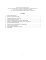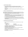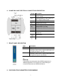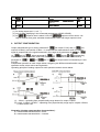
1
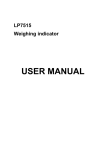
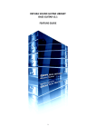
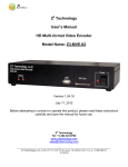
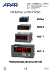
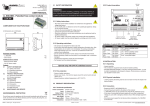
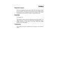
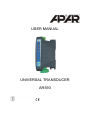
USER MANUAL
UNIVERSAL TRANSDUCER
AR593
Thank you for choosing our product.
This user manual will tell you how to use the transducer in a correct and safe way.
Please read it carefully before installing the transducer.
If you have any questions, please contact our technical department.
CONTENTS
1.
SAFETY PRECAUTIONS
.............................................................................................
2.
INSTALLATION INSTRUCTIONS
3.
TRANSDUCER CHARACTERISTICS ............................................................................
4.
TECHNICAL SPECIFICATIONS
5.
INSTALLATION DETAILS AND HOUSING DIMENSIONS
6.
CLAMP RAIL AND ELECTRICAL CONNECTORS DESCRIPTION
7.
FRONT PANEL DESCRIPTION
8.
CONFIGURATION PARAMETERS PROGRAMMING
9.
OUTPUT CONFIGURATION
.................................................................................. 2
2
.................................................................................. 3
...........................................
............................
4
5
..................................................................................... 5
.................................................
6
........................................................................................ 7
10. MEASUREMENT ERRORS INDICATION
11. OWN NOTES
2
...................................................................
8
...............................................................................................................
8
1
1. SAFETY PRECAUTIONS
•
•
•
•
Please read this user manual carefully before using the transducer.
To avoid instrument damage, check if all connections are correct before turning on the
transducer.
Use the transducer in appropriate conditions only (supply voltage, humidity and
temperature).
Before making any changes in electrical connections, please turn off power supply of the
transducer.
2. INSTALLATION INSTRUCTIONS
This instrument has been designed to ensure the proper level of resistance to most noises,
which can appear in industry environment. It is recommended to apply precautions listed below
while working in environment where the level of disturbance is unknown:
• Do not connect the transducer to the same line with other high power devices without
appropriate line filters.
• Use shielded power supply cables, sensor cables and signal cables. Shield grounding
should be on one side of the cable, as close to the instrument as possible.
• Avoid placing measurement (signal) cables close to and in parallel with power cables.
• It’s recommended to twist signal cables in pairs.
• Use cables with the same parameters for resistance sensors with 3 wire connection.
• Avoid placing transducer close to remotely controlled devices, electromagnetic meters,
high power loads, loads with phase or common power regulation and other devices with
high pulse noises.
• Connect metal rails with devices to ground or zero wire.
3. TRANSDUCER CHARACTERISTICS
•
•
•
•
•
•
•
•
•
Linear transformation of measured temperature or other signal to current or voltage
signal.
Universal input:
o Thermo-resistance..........................Pt100, Ni100
o Thermocouple.................................J, K, S, B, R, T
o Analog.............................................0/4÷20mA, 0÷10V, 0÷60mV, resistance
Two independent outputs (current 0/4÷20mA and voltage 0÷10V, measurement
retransmission or programmable alarm)
Triple galvanic isolation (input / output / supply)
Slim housing for TS35 (DIN) rail installation
Transformation range, input type and other parameters configurable with AR950
programmer or AR955 programmer set.
Programmed alarms for preset value exceeding with hysteresis.
LED indication for transformation range exceeding, sensor error or alarm output status
(on – off type).
High accuracy and noise resistance.
2
4. TECHNICAL SPECIFICATIONS
Universal input (programmable), full measurement range:
RTD:
Thermocouple:
- Pt100 (3 or 2 wires)..................
-200 ÷ 850°C (input default value)
- Ni100 (3 or 2 wires)..................
-50 ÷ 170°C
- J type........................................
0 ÷ 800°C
- K type........................................ 0 ÷ 1200°C
- S type........................................ 0 ÷ 1600°C
- B type........................................ 300 ÷ 1800°C
- R type.......................................
0 ÷ 1600°C
- T type........................................
0 ÷ 350°C
- Electronic temperature compensation for cold thermocouple ends
Analog:
- current (Rwe = 110Ω)...............
0 ÷ 20mA, 4÷20mA
- voltage (Rwe = 100kΩ).............
0 ÷ 10V
- voltage (Rwe > 5MΩ)................
0 ÷ 60mV
- resistance.................................
0 ÷ 1000Ω
Allowed leads resistance for resistance inputs
(RTD, 0÷1kΩ)................................................................
Rd < 30Ω (3 wires, for each wire)
Resistance input current (RTD, 0÷1kΩ)....................
~250µA
Transformation ranges (2 independent).....................
0 ÷ 500°C (programmed within input
measurement range)
Outputs (programmable)
- current....................................... 0/4÷20mA, 20÷4/0mA
- load resistance....................
Ro ≤ 500Ω
- resolution............................
2.6µA
- voltage......................................
0÷10V, 10÷0V
- load resistance....................
Rw > 2.5kΩ
- resolution............................
1.3mV
Main transformation error (25°C)...............................
≤0.1% of full input measurement range
± 1 transformation range step
Additional error for thermocouple inputs.................
<2°C (cold ends temperature)
Additional error from temperature changes.............
≤0.01% of transformation range/°C
Temperature measurement resolution...................
0.1°C
Response time (10÷90%)............................................
360ms, programmed with
parameter from 240 to 1600ms
Power supply...............................................................
24V AC/DC (18÷50V DC, 14÷35V AC)
- power consumption.....................................................
< 850mW
3
Isolation (input/output/supply)..................................
1.5kV, 50Hz, 1min
Error indication.........................................................
Red LED (A1, A2) and output signals
(3.8mA(1), 21mA(1), 21.25mA(2),
10.625V(3))
Operating temperature...............................................
0 ÷ 65°C
Relative humidity range.............................................
0 ÷ 90% RH (non condensed)
Protection class..........................................................
IP20
Working position.........................................................
Any
Weight..........................................................................
~95g
Electromagnetic
compatibility
(EMC)
- resistance : according to PN-EN 61000-6-2:2002(U)
- emissivity : according to PN-EN 61000-6-4:2002(U)
Transmission parameters for AR955 programmer..
2400bit/s, address MODBUS=1
Notes:
(1) – for 4 ÷ 20mA output
(2) – for 0 ÷ 20mA output
(3) – for 0 ÷ 10V output
5. INSTALLATION DETAILS AND HOUSING DIMENSIONS
Dimensions ........................
Installation ........................
Material
........................
17.5 x 120 x 101mm
On TS35 (DIN EN
50022-35) rail
Polycarbonate, ABS UL
94V-0
4
6. CLAMP RAIL AND ELECTRICAL CONNECTORS DESCRIPTION
Clamps Description
1-2-3
Pt100, Ni100 input, resistance 0÷1kΩ
(2 and 3 wires)
2-3
Thermocouple TC (J, K, S, B, R, T)
and voltage (0÷60mV) input
3-5
Current input (0/4÷20mA)
4-5
Voltage input (0÷10V)
6-7
Power supply input (24V AC/DC)
8-9
Analog output 1 (0÷10V)
9-10
Analog output 2 (0/4 ÷ 20mA)
Ro, Rw
Measurement instrument load
resistances
Milliammeter
Voltmeter
7. FRONT PANEL DESCRIPTION
Item
PR
A1
A2
Description
Programming socket
LED indication for transformation range
exceeding, sensor error or alarm output status (on
– off type) for output 1 (0÷10V)
LED indication for transformation range
exceeding, sensor error or alarm output status (on
– off type) for output 2 (0/4÷20mA)
CAUTION:
Connecting instruments other than AR950 programmer or
AR955 programmer to PR socket may cause damage to
connected instrument and AR593 transducer.
8. CONFIGURATION PARAMETERS PROGRAMMING
5
•
•
To set configuration parameters, perform steps below:
a) Turn on the transducer power supply,
b) Open the front transparent transducer cover,
c) Connect AR950 or AR955 programmer to PR socket (2400bit/s, address MODBUS=1)
d) Proceed according to the programmer user manual instructions.
After turning the transducer on for the first time, LED indication for transformation range
exceeding or sensor error may occur. This error can occur when the sensor is not
connected or other than default sensor is connected – you should connect the correct
sensor, the analog input or change the configuration setup.
Table 1. Configuration parameters
No.
Item
0
Param.
Input
(sensor)
type
1
2
(2)
Parameter Value and Range
RTD
=Pt100,
Thermocouple
= J,
=S,
Current
=4÷20mA,
Voltage
=0÷10V,
Resistance
=0÷1000Ω
÷
Display resolution
= 1°C,
or decimal point position (1)
=0,
3
Input scale beginning (1)
4
=Pt100
=Ni100
=K,
Filter level (3)
Factory
=B,
=R,
=T
=0÷20mA
=0÷60mV
=0.1°C
=0.0,
=0.1°C
=0.00,
=0.000
÷
(for 0mA, 4mA, 0V, 0Ω)
Input scale end (1)
÷
1000Ω)
(for 20mA, 10V, 60mV,
5
Output 1 characteristic (0÷10V),
(see section 9)
=measurement retransmission,
=inversion (heating), =direct
(cooling)
6
Output 1 alarm value (0÷10V)
Within input measurement range
7
Output 1 hysteresis
8
Output 1 scale beginning (for 0V)
Within input measurement range
9
Output 1 scale end (for 10V)
Within input measurement range
10
Output 2 type (0/4÷20mA)
11
Output 2 characteristic
(0/4÷20mA), (see section 9)
=measurement retransmission,
=inversion (heating), =direct
(cooling)
12
Output 2 alarm value (0/4÷20mA)
Within input measurement range
13
Output 2 hysteresis
14
Output 2 scale beginning (for
0mA or 4mA)
÷
°C or
=4÷20mA,
÷
÷
units (1)
°C
°C
°C
=0÷20mA
°C or
÷
units (1)
Within input measurement range
6
°C
°C
°C
°C
User
15
Output 2 scale end (for 20mA)
Within input measurement range
16
Zero shift
÷
units (1)
17
Amplification
÷
°C or
%
÷
°C
°C
%
Notes:
(1) for analog inputs (mA, V, mV, Ω)
(2) only for data displaying in the connected programmer (AR950, AR955),
(3) for
= response time is about 0.24s, for
=
response time is about 1.6s.
Higher filtration level gives smoother measurement value and longer response time.
9. OUTPUT CONFIGURATION
Output characteristic type is set by parameter 5:
(for output 0÷10V) and 11:
(for
output 0/4÷20mA), see section 8, table 1. In measurement retransmission mode, the output
, 9:
,
signal is proportional to the signal measured in the range set by parameter 8:
14:
and 15:
. When parameter 5:
, 11:
equals or corresponding
output is switched to the alarm mode with ON-OFF type. The alarm mode is controlled by
, 7:
, 12:
and 13:
and output status is indicated by A1 and
parameter 6:
A2 LED.
Independent operation of each output allows configuring two different transformation ranges,
operation modes, alarm values and hysteresis.
Operating principle of analog outputs for each operation mode is shown below.
(1) – 3.8mA – spreading from proportionality range bottom for output 4÷20mA
(2) 21mA, 21.25mA, 10.625V – spreading from proportionality range top for outputs 4÷20mA,
0÷20mA and 0÷10V
Illustration (Analog output working characteristics):
a) measurement retransmission – direct
b) measurement retransmission – inverted
7
c) alarm output – inverted
d) alarm output – direct
10. MEASUREMENT ERROR INDICATION
Transducer indicates the following measurement errors:
- exceeding transformation range (up or down)
- connected sensor or input signal other than defined in configuration parameters
- sensor circuit malfunction
Measurement error indication:
- A1 or A2 LED blinking (only in the measurement retransmission mode)
11. OWN NOTES
8