1
1575H112 Ed.02
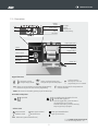
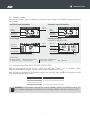
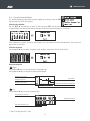
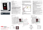
4.1.- Wiring
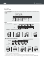
Supply and outputs
CAUTION: The power supply circuit should be equipped with a switch for turning it off, located close to
the device.
6 A cos j = 1 250V
1
2
3
4
5
6
7
8
9
10 11 12 13 14 15
Tr
+
Outputs of
+12 Vcc *
Input
Output
Output
100- MAXIMUM MINIMUM
240 Vac ALARM
ALARM
Tr
G
nd
NO C NC NO C NC
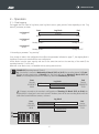
Probes
AKO-15740/15742
2
INPUT NO.
1
4
6
3
10
8
7
5
9
16 17 18 19 20 21 22 23 24 25 26 27 28 29 30
NTC
Pt1000
Example of connection of other probes:
DIGITAL
INPUT
4-20 mA
3 wires
n
4-20 mA
2 passive wires
n
n
n
**
x x x
n
**
**
x x x
n
n
1
2
n
**
x x x
AKO-15750/15752/15780/15782
INPUT NO.
4-20 mA
2 active wires
x x x
Only AKO-1575x
3
4
5
16 17 18 19 20 21 22 23 24 25 26 27 28 29 30
NTC
Pt1000
Example of connection of other probes:
Pt100
DIGITAL
INPUT
n
n
x x x
x x x
4-20 mA
3 wires
**
n
x x x
**
4-20 mA
2 passive wires
4-20 mA
2 active wires
n
n
x x x
x x x
* The sum of the 4 outputs must not exceed 250 mA
** Connect to one of the + 12V output terminals (terminals 9 al 12) (Not available in battery mode operation)
For more information about the connection of humidity probes consult Manual 358004001 on our website: www.ako.com
12