1
d
e
Place the panel in the selected position and mark the three fixing holes.
Mount the Panel securely using all three positions.
WIRING THE CONTROL PANEL
1
Mains connection
The mains supply should be connected via one of the separated cable entries
provided. Connections should be made to the 3 way terminal block located
in bottom left of panel and wired in accordance with the relevant IEE
regulations via a fused spur. The panel must be earthed.
IF IN DOUBT CONSULT A QUALIFIED ELECTRICIAN.
2
Battery connection.
The Securit 700L requires a standby battery to be fitted to provide power in
the event of the mains failure. A sealed lead acid battery should be fitted.
Batteries up to 6 Ah may be used.
3
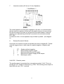
Detector circuits
Connections are provided for up to seven detector circuits of which normally
closed detection devices should be used. A common tamper loop is provided
for all detection devices marked as 24 HR Tamper. One or more devices may
be connected to each alarm circuit. These should be connected in series.
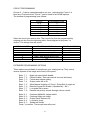
These circuit connections are located to the bottom right of the PCB
(see diagram B).
4
PIR Latch Line (L+)
In the event of two or more PIR detectors being fitted to any single zone,
latching detectors should be used. The 'L+' connection provides this
function. It is low (0 V) when unset and high (12 V) when set. It should be
connected to the appropriate SET or LATCH terminal in the detector.
5
AC power connector
Make sure after Mounting the panel and replacing the PCB that you connect
the white plug with the 3 wires to the 3 pins located in the top left hand corner
of the PCB. This will ensure AC power gets from the transformer to the PCB.
6
Detector reset (ID)
Some detectors require the removal of power to reset (e.g. Viper Plus or
Smoke detectors). The 'ID' output should be used as the negative supply for
these devices. The positive supply should be taken from the AUX +.
This output can be programmed to signal mains fail by selecting option 7-5.
When selected it will signal 10 minutes after the removal of the mains power
and restore one minute after the mains power returns.
3