1
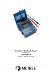
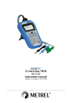
MicroOhm 10A MI 3250 Instruction manual Version 1.0, Code no 20 751 893 Distributor: Manufacturer: METREL d.d. Ljubljanska cesta 77 1354 Horjul Slovenia web site: http://www.metrel.si e-mail: [email protected] Mark on your equipment certifies that this equipment meets the requirements of the EU (European Union) concerning safety and electromagnetic compatibility regulations © 2011 METREL No part of this publication may be reproduced or utilized in any form or by any means without permission in writing from METREL. 2 MI 3250 MicroOhm 10A Table of contents Table of contents 1 General description ............................................................................................ 5 1.1 Features.......................................................................................................... 5 2 Safety and operational considerations ............................................................. 6 2.1 Warnings and notes ........................................................................................ 6 2.2 Battery and charging....................................................................................... 8 2.2.1 New battery cells or cells unused for a longer period ................. 9 2.3 Standards applied ......................................................................................... 10 3 Instrument Description ..................................................................................... 11 3.1 Operator’s Panel ........................................................................................... 11 3.2 Connectors and Battery cover ...................................................................... 12 3.2.1 Test leads connector ............................................................... 12 3.2.2 Connector panel (right side) .................................................... 13 3.2.3 Connector panel (left side)....................................................... 14 3.3 Accessories .................................................................................................. 15 3.4 Display organization...................................................................................... 16 3.4.1 Measurement result window ................................................... 16 3.4.2 Measurement control window ................................................. 17 3.4.3 Message window ..................................................................... 17 3.4.4 Battery and time indication..................................................... 18 3.4.5 Backlight operation................................................................ 18 4 Main menu ......................................................................................................... 19 4.1 Instrument Main menu .................................................................................. 19 4.2 Memory Menu............................................................................................... 20 4.2.1 Saving results ......................................................................... 20 4.2.2 Recalling results ..................................................................... 21 4.2.3 Deleting results ...................................................................... 22 4.2.4 Clearing complete memory content ......................................... 22 4.3 Settings menu............................................................................................... 23 4.3.1 Language selection ................................................................. 23 4.3.2 Communication selection........................................................ 23 4.3.3 Set Date and Time .................................................................. 24 4.3.4 Set Contrast ........................................................................... 24 4.3.5 Temperature Compensation .................................................... 25 4.3.6 Set Limits ............................................................................... 27 4.3.7 Instrument info....................................................................... 27 4.4 Help Menu .................................................................................................... 28 5 Measurement ..................................................................................................... 29 5.1 Four wire Kelvin method ............................................................................... 29 5.2 Resistance measurement ............................................................................. 30 5.2.1 Single Mode ............................................................................ 31 5.2.2 Continuous Mode ................................................................... 31 5.2.3 Automatic Mode...................................................................... 32 5.2.4 Inductive Mode ....................................................................... 33 6 Communication ................................................................................................. 34 7 Maintenance ...................................................................................................... 35 3 MI 3250 MicroOhm 10A 7.1 7.2 7.3 8 Table of contents Cleaning........................................................................................................ 35 Periodic calibration........................................................................................ 35 Service.......................................................................................................... 35 Technical specifications................................................................................... 36 8.1 Resistance measurement ............................................................................. 36 8.2 Measurement parameters............................................................................. 37 8.3 General data ................................................................................................. 37 4 MI 3250 MicroOhm 10A General description 1 General description 1.1 Features MicroOhm 10A (MI 3250) is a portable (2.8 kg) bidirectional low resistance ohmmeter using four wire Kelvin method to measure low resistances of: Switches Relays Connectors Bus bars Power distribution cable joints Motor & generator winding Power transformers Power inductors Rail track joints Wire and cable resistance Welding joints. Instrument can be powered from mains or internal rechargeable batteries. It is designed and produced with the extensive knowledge and experience acquired through many years of of working in this field. Available functions and features offered by the MicroOhm 10A meter: Resistance measurement (Four wire Kelvin method); High Resolution measurement (24-Bit Σ-Δ ADC); Auto or Manual Range Wide measuring range (0.1 μΩ ... 2 kΩ); Adjustable test current (1 mA ...10 A); Temperature compensation; Hi/Lo limits; Automatic thermal EMF elimination; Four different measuring modes (single, continuous, inductive, automatic); USB and RS232 communication; High overvoltage category CAT IV / 300 V. A 320x240 dot matrix LCD offers easy-to-read results and all associated parameters. The operation is straightforward and clear to enable the user to operate the instrument without the need for special training (except reading and understanding this Instruction Manual). Test results can be stored on the instrument. PC software HVLink PRO that is supplied as a part of standard set enables transfer of measured results to PC where can be analysed or printed. 5 MI 3250 MicroOhm 10A Safety and operational considerations 2 Safety and operational considerations 2.1 Warnings and notes In order to maintain the highest level of operator safety while carrying out various tests and measurements Metrel recommends keeping your MicroOhm 10A instruments in good condition and undamaged. When using the instrument, consider the following general warnings: The symbol on the instrument means »Read the Instruction manual with special care for safe operation«. The symbol requires an action! If the test equipment is used in a manner not specified in this user manual, the protection provided by the equipment could be impaired! Read this user manual carefully, otherwise the use of the instrument may be dangerous for the operator, the instrument or for the equipment under test! Do not use the instrument or any of the accessories if any damage is noticed! Consider all generally known precautions in order to avoid risk of electric shock while dealing with hazardous voltages! Do not use the instrument in supply systems with voltages higher than 300 V! Service intervention or adjustment is only allowed to be carried out by competent authorized personnel! Use only standard or optional test accessories supplied by your distributor! Consider that older accessories and some of the new optional test accessories compatible with this instrument only meet CAT II / 300 V over voltage safety rating! This means that maximal allowed voltage between test terminals and ground is 300 V! The instrument comes supplied with rechargeable Ni-Cd or Ni-MH battery cells. The cells should only be replaced with the same type as defined on the battery compartment label or as described in this manual. Do not use standard alkaline battery cells while the power supply adapter is connected, otherwise they may explode! Hazardous voltages exist inside the instrument. Disconnect all test leads, remove the power supply cable and switch off the instrument before opening the battery compartment. All normal safety precautions must be taken in order to avoid risk of electric shock while working on electrical installations! 6 MI 3250 MicroOhm 10A Safety and operational considerations Warnings related to measurement functions: Resistance and inductive measurement Resistance measurement should only be performed on de-energized objects! Do not touch the test object during the measurement or before it is fully discharged! Risk of electric shock! When a resistance measurement has been performed on an inductive object, automatic discharge may not be done immediately! High voltage can appear on test terminals when measuring inductive object! Do not connect test terminals to external voltage higher than 300 V (AC or DC) in order not to damage the test instrument! General Warning will appear on screen and the resistance test will not be performed if voltages higher than 8 V (AC or DC) are detected between test terminals. There will be no warning if all terminals are at the same potential. PASS / FAIL indication is enabled when limit is set. Apply appropriate limit value for evaluation of measurement results. 7 MI 3250 MicroOhm 10A Safety and operational considerations 2.2 Battery and charging The instrument uses six alkaline or rechargeable Ni-Cd or Ni-MH battery cells. Nominal operating time is declared for cells with nominal capacity of 3500 mAh. Battery condition is always displayed in the upper right display part. In case the battery is too weak the instrument indicates this as shown in figure 2.1. Figure 2.1: Discharged battery icon The battery is charged whenever the power supply is connected to the instrument. The power supply socket is shown in figure 2.2.Internal circuit controls charging and assures maximum battery lifetime. Figure 2.2: Power supply socket The instrument automatically recognizes the connected power supply and begins charging. Symbols: Indication of battery charging Figure 2.3: Charging indication When connected to an installation, the instruments battery compartment can contain hazardous voltage inside! When replacing battery cells or before opening the battery compartment cover, disconnect any measuring accessory connected to the instrument and turn off the instrument, Ensure that the battery cells are inserted correctly otherwise the instrument will not operate and the batteries could be discharged. If the instrument is not to be used for a long period of time, remove all batteries from the battery compartment. Alkaline or rechargeable Ni-Cd or Ni-MH batteries can be used. Metrel recommends only using rechargeable batteries with a capacity of 3500mAh or above. Do not recharge alkaline battery cells! 8 MI 3250 MicroOhm 10A Safety and operational considerations 2.2.1 New battery cells or cells unused for a longer period Unpredictable chemical processes can occur during the charging of new battery cells or cells that have been left unused for a longer period (more than 3 months). Ni-MH and NiCd cells can be subjected to these chemical effects (sometimes called the memory effect). As a result the instrument operation time can be significantly reduced during the initial charging/discharging cycles of the batteries. In this situation, Metrel recommend the following procedure to improve the battery lifetime: Procedure Completely charge the battery. Notes At least 6h (3500mAh) with in-built charger. This can be performed by using the Completely discharge the battery. instrument normally until the instrument is fully discharged. Repeat the charge / discharge cycle at Four cycles are recommended in order to least 2-4 times. restore the batteries to their normal capacity. Notes: The charger in the instrument is a pack cell charger. This means that the battery cells are connected in series during the charging. The battery cells have to be equivalent (same charge condition, same type and age). One different battery cell can cause an improper charging and incorrect discharging during normal usage of the entire battery pack (it results in heating of the battery pack, significantly decreased operation time, reversed polarity of defective cell, …). If no improvement is achieved after several charge / discharge cycles, then each battery cell should be checked (by comparing battery voltages, testing them in a cell charger, etc). It is very likely that only some of the battery cells are deteriorated. The effects described above should not be confused with the normal decrease of battery capacity over time. Battery also loses some capacity when it is repeatedly charged / discharged. Actual decreasing of capacity, versus number of charging cycles, depends on battery type. This information is provided in the technical specification from battery manufacturer. 9 MI 3250 MicroOhm 10A Safety and operational considerations 2.3 Standards applied The MicroOhm 10A instrument is manufactured and tested in accordance with the following regulations: Electromagnetic compatibility (EMC) EN 61326 Electrical equipment for measurement, control and laboratory use – EMC requirements Class A Safety (LVD) EN 61010-1 Safety requirements for electrical equipment for measurement, control and laboratory use – Part 1: General requirements EN 61010-031 Safety requirements for hand-held probe assemblies for electrical measurement and test Note: Immunity to radiated RF fields (Field strength: 10V/m, Modulation: AM, 80%, 1 kHz) Current Range 1mA Operational conditions Range 2kΩ Disturbance > 0,25 % Disturbance < 0,25 % 100 MHz ÷ 500 MHz 500 MHz ÷ 1 GHz Note about EN and IEC standards: Text of this manual contains references to European standards. All standards of EN 6XXXX (e.g. EN 61010) series are equivalent to IEC standards with the same number (e.g. IEC 61010) and differ only in amended parts required by European harmonization procedure. 10 MI 3250 MicroOhm 10A Safety and operational considerations 3 Instrument Description 3.1 Operator’s Panel The operator’s panel is shown in Figure 3.1 below. Figure 3.1: Front panel Legend: 1 START / STOP 2 ON / OFF 3 MEM 4 SELECT 5, 6 7, 8 9 ESC 10 LIGHT Start or stop measurement. Switches the instrument power on or off. The instrument automatically turns off 15 minutes after the last key was pressed. Store / recall / clear tests in memory of instrument. To enter set-up mode for the selected function or to select the active parameter to be set. Select an option upward, downward. Decrease, increase the selected parameter. Exit the selected mode. Turn the display backlight ON or OFF. Instrument’s RESET (hold key for 3 s or more). 11 MI 3250 MicroOhm 10A 2BInstrument Description 3.2 Connectors and Battery cover The MicroOhm 10A tester contains the following terminals: Four banana safety sockets, for connection of test leads (Figure 3.2), Mains socket, for connection of mains supply cable (Figure 3.3), Communication terminals (USB and RS232) (Figure 3.3), Battery cover (Figure 3.4). 3.2.1 Test leads connector Figure 3.2: Test leads connector Legend: 1 2 3 4 C1 C2 P1 P2 Current terminals Measuring inputs / outputs Voltage terminals Warnings! Maximum allowed voltage between any test terminal and ground is 300 V! Maximum allowed voltage between test terminals is 300 V! Use original test accessories only! 12 MI 3250 MicroOhm 10A Instrument description 3.2.2 Connector panel (right side) Figure 3.3: Communication and mains connectors Legend: 1 RS232 connector 2 3 USB connector Mains connector Communication with PC RS232 port. Communication with printer. Communication with PC USB (1.1) port. Mains supply of the instrument and battery charger supply Warnings! Maximum allowed voltage between L-N (Mains connector) is 300 V (CAT II)! Use original test accessories only! 13 MI 3250 MicroOhm 10A Instrument description 3.2.3 Connector panel (left side) Figure 3.4: Measuring inputs/outputs and battery compartment Legend: 1 2 Measuring inputs / outputs. Battery compartment. Figure 3.5: Correct inserted batteries Warnings! When connected to an installation, the instruments battery compartment can contain hazardous voltage inside! Disconnect all test leads, remove the power supply cable and switch off the instrument before opening the battery compartment. Ensure batteries are used and disposed of in accordance with Manufacturers guidelines and in accordance with Local and National Authority guidelines. 14 MI 3250 MicroOhm 10A Instrument description 3.3 Accessories The accessories consist of standard and optional accessories. Optional accessories can be delivered upon request. See attached list for standard configuration and options or contact your distributor or see the METREL home page: http://www.metrel.si. Figure 3.6: Standard set of the instrument Instrument MI 3250 MicroOhm 10A Current test leads with crocodile clip, 2,5 m, 2,5 mm2, 2 pcs (Kelvin) Current test leads 2,5 m, 2,5 mm2, 2 pcs (red) Potencial test leads 2,5 m, 1,5 mm2, 2 pcs (black) Crocodile clips, 4 pcs (black, red) Test probes, 2 pcs (black) Mains cable NiMH rechargeable batteries, 3500mAh, 6 pcs RS232 serial cable USB cable Bag for accessories PC SW HVLink PRO Instruction manual Calibration certificate 15 MI 3250 MicroOhm 10A Instrument description 3.4 Display organization 1 2 3 4 Measurement result window Measurement control window Messages window Battery and time indication Figure 3.7: Typical function display 3.4.1 Measurement result window Measurement window shows all relevant data during measurement campaign. Figure 3.8: Measurement window Measured resistance is shown in the center of a screen with the largest font. During measurement campaign this result is refreshed every few seconds. After finishing measurement result is hold on screen, until new measurement is started. Bar graph graphically represents measured resistance in respect to the measurement range. R+ shows resistance in the positive direction. During measurement campaign this result is refreshed every few seconds. After finishing measurement result is hold on screen, until new measurement is started. R- shows resistance in the negative direction. During measurement campaign this result is refreshed every few seconds. After finishing measurement result is hold on screen, until new measurement is started. Ix shows current flow through the measured resistance. During measurement campaign this result is refreshed every few seconds. After finishing measurement result is hold on screen, until new measurement is started. Amb shows the value of the ambient temperature that was measured with the temperature probe or was entered manually (appears when the temperature compensation is turned on). Ref@ shows the value of the reference temperature that was entered manually (appears when the temperature compensation is turned on). Dis: shows the discharging time (appears only in inductive mode). 16 MI 3250 MicroOhm 10A Instrument description 3.4.2 Measurement control window Control window permit user to modify control measurement parameters. Figure 3.9: Control window Mode allows user to select desired measuring mode. It is possible to select one of following modes: Single, Automatic, Continuous and Inductive. See chapter 5.2 for more details. Auto Range allows user to select or deselect automatic range selection. Range allows user to select desired measuring range. It is possible to select one of following ranges: 2 mΩ, 20 mΩ, 200 mΩ, 2 Ω, 20 Ω, 200 Ω, 2 kΩ. Current allows user to select proper current for resistance measurement. It is possible to select one of following currents: 1 mA, 10 mA, 100 mA, 1 A, 10 A. Notes: Auto Range is always deselected in Inductive mode. Resistance range depends on selected current. Example: with selected 1 A current, only 20 mΩ, 200 mΩ and 2 Ω ranges can be selected. See table 8.1 for more details. 3.4.3 Message window In the message field warnings and messages are displayed. No batteries or wrong polarity of inserted batteries. Battery charging in progress. High voltage is present on measuring terminals. Measurement in progress. 17 MI 3250 MicroOhm 10A 2BInstrument Description Instrument is overheated. Measurement process is disabled. Battery supply voltage is low. P1, P2, C1 or C2 terminal is not connected to the instrument or too high resistance is detected. Measurement current and result is within defined limits. Measurement current is out of defined limits. Measurement result is out of defined high limit. Measurement result is out of defined low limit. 3.4.4 Battery and time indication The indication indicates the charge condition of battery and charger connection. Battery capacity indication. Low battery. Battery is too weak to guarantee correct result. Replace or recharge the battery cells. Recharging in progress (if mains supply cable is connected). Time indication (hh:mm). Note: Date and time is attached to each stored result. 3.4.5 Backlight operation After turning the instrument ON the LCD backlight is automatically turned ON. It can be turned OFF and ON by simply clicking the LIGHT (☼) key. Note: If you press and hold the Light (☼) key for approximately 5 s the instrument will RESET! 18 MI 3250 MicroOhm 10A Main menu 4 Main menu 4.1 Instrument Main menu From the main menu of the instrument there are four options available: Measurement, Memory Menu, Settings Menu and Help Menu. Figure 4.1: Instrument Main menu Keys: SELECT Select one of the following menu items: <Measurement> See chapter 5.2; <Memory Menu> Memory management, see chapter 4.2; <Settings Menu> Setup of the instrument, see chapter 4.3; <Help Menu> Help screens, see chapter 4.4; Confirms selection. 19 MI 3250 MicroOhm 10A Main menu 4.2 Memory Menu Measurement result with all relevant parameters can be stored into the instrument’s memory. The instrument’s memory space is divided into 2 levels: Object and Number of Results. The upper Object level can contain up to 199 locations. The number of measurements stored under single object location is not limited. Figure 4.2: Memory Menu 4.2.1 Saving results After the completion of a test, the results and parameters are ready for storing. By pressing the MEM key the user can enter storing menu. Figure 4.3: Storing Menu Keys: MEM ESC Selects Object number. Saves measurement result to selected object number and returns to the Measurement result screen. Returns to the Measurement result screen without save. The instrument will beep in order to indicate that result is successfully saved into the memory. Note: Every stored test result also includes date and time stamp (dd:mm:yyyy, hh:mm). 20 MI 3250 MicroOhm 10A Main menu 4.2.2 Recalling results To enter Recall results menu in Memory menu SELECT key should be pressed. Figure 4.4: Recall Menu Figure 4.5: Recalled result screen Keys in Recall menu: SELECT ESC Selects one of the following items [Object; No. of results]. Decrees or increase the parameter. Recalls result in selected location. Returns to the Memory Menu. Keys in Recall result screen: ESC Toggles between the saved results under selected Object. Returns to the Recall Menu. 21 MI 3250 MicroOhm 10A Main menu 4.2.3 Deleting results To enter Delete results menu in Memory menu SELECT key should be pressed. Single measurement or all measurements under selected Object can be deleted. Figure 4.6: Delete all measurements under selected Object Keys in Delete menu: SELECT ESC Selects one of the following items [Object; No. of results]. Decrees or increase the parameter. Enters Delete confirmation screen. Returns to the Memory Menu. Keys in Delete confirmation screen: SELECT ESC Deletes result(s) in selected location. Returns to the Delete Menu without changes. 4.2.4 Clearing complete memory content When selecting the Clear All Memory function in Memory menu all the memory content will be deleted. Keys in Clear all memory confirmation screen: SELECT ESC Clears all memory content. Returns to the Memory Menu without changes. 22 MI 3250 MicroOhm 10A Main menu 4.3 Settings menu In the Settings menu different parameters and settings of the instrument can be viewed or set. Figure 4.7: Settings menu Keys: SELECT ESC Select the setting to adjust or view: <Language> instrument language; <Communication> communication port selection; <Set Date and Time> date and time; <Set Contrast> LCD contrast settings; <Temperature Compensation> temperature compensation settings; <Set Limits> limit values selection; <Instrument Info> basic instrument information; Confirms selection. Returns to the Main menu. 4.3.1 Language selection The instrument language can be set. Keys: Toggles between different languages. Note: No confirmation is needed to set the desired language. 4.3.2 Communication selection The instrument communication port can be set. Keys: Toggles between RS232 and USB. Note: No confirmation is needed to set the desired communication port. 23 MI 3250 MicroOhm 10A Main menu 4.3.3 Set Date and Time To enter Date and Time menu SELECT key should be pressed. Figure 4.8: Date and time menu Keys: SELECT ESC Select the parameter to be changed. Decrees or increase the parameter. Confirms selection and returns to the Settings menu. Returns to the Settings menu without changes. Warning: If the batteries are removed of the instrument the time and date will be lost. 4.3.4 Set Contrast In this menu the contrast of the display can be set. To enter Set Contrast menu SELECT key should be pressed. Figure 4.9: Set Contrast menu Keys: ESC Sets contrast value. Returns to the Settings menu (changes are stored automatically). Note: When using the instrument in a cooled environment contrast level should be decreased. 24 MI 3250 MicroOhm 10A Main menu 4.3.5 Temperature Compensation The temperature compensation is used to adjust the measured resistance, which depends on the ambient temperature, to the value it would have at the reference temperature. Figure 4.10: Compensation menu Figure 4.11: Coefficient menu Keys in Temperature Compensation menu: SELECT ESC Select the parameter to be changed. <Compensation> Set compensation [On, Off]; <Set Reference Temp> Reference temperature value; <Temperature> Ambient temperature settings [Manual, Probe]; <Set Ambient Temp> Ambient temperature value; <Coefficient Menu> Coefficient settings (see figure 4.12); Decrees or increase the parameter. Enters Coefficient menu. Returns to the Settings menu (changes are stored automatically). Keys in Coefficient menu: ESC Select the parameter to be changed. Decrees or increase the parameter. Returns to the Temperature Compensation menu (changes are stored automatically). Resistance measurement with the temperature compensation: Temperature compensation calculation Rref _ temp Ramb _ temp 1 ref _ temp 1 amb _ temp Legend: Rref _ temp Compensated resistance calculated to the reference temperature. Ramb _ temp Resistance measured at the ambient temperature. ppm / C Temperature coefficient of the measured object (Cu, Al…, user defined). Reference temperature which the measurement is referred to (user defined). Ambient temperature measured with the temperature probe or user defined. ref _ tempC amb _ tempC 25 MI 3250 MicroOhm 10A Main menu Example: Ramb _ temp 118.44m 4100 ppm / C ( Al ) ref _ temp 25C amb _ temp 40C Rref _ temp Ramb _ temp 1 ref _ temp 118.44m 1 4100 ppm / C 25C 112.18m 1 amb _ temp 1 (4100 ppm / C 40C ) R25C 112.18m Measurement window shows the compensated value. Figure 4.13: Compensated result example This table shows the temperature coefficient of various materials at 20 °C (68 °F) Material Symbol Aluminium Copper Gold Iron Nickel Platinum Silver Zinc Al Cu Au Fe Ni Pt Ag Zn Temperature coefficient ppm / C 4100 3930 3715 5671 5866 3729 3819 3847 Resistivity m 2,82×10⁻⁸ 1,68×10⁻⁸ 2,44×10⁻⁸ 1,0×10⁻⁷ 6, 99×10−8 1,06×10⁻⁷ 1,59×10⁻⁸ 5,90×10⁻⁸ Table 4.1: Temperature coefficient and resistivity 26 MI 3250 MicroOhm 10A Main menu 4.3.6 Set Limits With Upper and Lower limits the user is allowed to set limit resistance values. Measured resistance is compared against those limits. Result is validated only if it is within the given limits. Figure 4.14: Setup limits menu Keys: ESC Select the parameter to be changed. Decrees or increase the parameter. Returns to the Settings menu (changes are stored automatically). 4.3.7 Instrument info In this menu the following instrument data is shown: hardware version; firmware version; serial number; calibration date; Figure 4.15: Instrument info screen Keys: ESC Returns to the Settings menu. 27 MI 3250 MicroOhm 10A Main menu 4.4 Help Menu The Help menu contains schematic diagrams for illustrating how to properly connect the instrument to the various test objects. Keys in help menu: ESC Selects next / previous help screen. Returns to the Settings menu. Figure 4.16: Examples of help screens 28 MI 3250 MicroOhm 10A Measurement 5 Measurement 5.1 Four wire Kelvin method When measuring resistance <20 Ω it is advisable to use a four wire measurement technique (Figure 5.1), for achieving high accuracy. By using this type of measurement configuration the test lead resistance is not included in the measurement, and the need for lead calibrating and balancing is eliminated. Figure 5.1: Four wire Kelvin method The measuring current is passed through the unknown resistance Rx using the C1 and C2 probes. The placing of these probes is not critical but should always be outside the P1 and P2 probes. The Voltage drop across the Rx is measured across P1 and P2 and these should be placed exactly at the points to be measured. Note about poor connection: Most measurement errors are caused by poor or inconsistent connection of the object under test. It is essential to ensure that the device under test has clean, oxide and dirt free contacts. High resistance connection will cause errors and may prevent the selected current to flow, because of the high resistance of C1 - C2 loop. Note: Ohm's law states that the current through a conductor between two points is directly proportional to the potential difference or voltage across the two points, and inversely proportional to the resistance between them. The mathematical equation that describes this relationship is: I Amper U Volt ROhm 29 Rx U Volt I Amper MI 3250 MicroOhm 10A Measurement 5.2 Resistance measurement Test can be started from the Measurement screen. Before carrying out a test the parameters (Mode, Range and Current) can be edited. Figure 5.2: Resistance menu Test parameters for Resistance measurement Mode Auto Range Range Current Single, Automatic, Continuous, Inductive Off, On 2 m20 m200 m2 20 200 2 k 10 A, 1 A, 100 mA, 10 mA, 1 mA Test circuits for Resistance measurement Figure 5.3: Measurement of Resistance Resistance measurement procedure: Select the Measurement function. Set the test parameters. Connect device under test to the instrument (see figure 5.3). Press the START / STOP key to start the measurement. Press the START / STOP key again to end the measurement (in continuous, automatic and inductive modes). Store the result by pressing MEM key (optional). 30 MI 3250 MicroOhm 10A Measurement Figure 5.4: Example of Resistance measurement result Note: Consider displayed warnings before starting measurement! 5.2.1 Single Mode Single mode makes a single bidirectional measurement. The instrument will measure resistance in both directions (thermal EMF elimination). The main result displayed on the R R display is an average ( R ). 2 The range and current output can be automatically set or user defined. Single measurement I/t plot Test I Start t +I -I u ADC t ADC t Figure 5.5: Single Mode Note: The Single Mode can be primarily used for measuring: Ralays Switches Connectors Bus bars Power distribution cable joints Welding joints 5.2.2 Continuous Mode Continuous mode makes continuous bidirectional measurements. The instrument will measure resistance in both directions (thermal EMF elimination) and repeating the measurements until the STOP key will be pressed. The main result displayed on the R R display is an average of the last bidirectional measurement ( R ). 2 The range and current output can be automatically set or user defined. 31 MI 3250 MicroOhm 10A Measurement The measurement is started and stopped by the user. Continuous measurement I/t plot Test I Start Stop t +I +I -I u ADC -I ADC ADC t ADC t Figure 5.6: Continuous Mode Note: The Continuous Mode is especially helpful for troubleshooting. 5.2.3 Automatic Mode Automatic mode makes a single bidirectional measurement. The instrument will measure resistance in both directions (thermal EMF elimination) and started a single measurement every time the P1, P2, C1 and C2 are connected to the test object. The main result displayed on the display is an average of the last bidirectional measurement R R (R ). 2 The range and current output can be user defined before the test or automatically set. To make another measurement simply break and remake contact with the test sample. Automatic measurement I/t plot Figure 5.7: Automatic Mode Note: The Automatic Mode can be primarily used for measuring Bus bars. 32 MI 3250 MicroOhm 10A Measurement Note about thermal EMF: A junction between two different metals produces a voltage related to a temperature difference (thermocouple). MicroOhm 10A eliminates the thermal EMF effect by measuring resistance in both directions I+ and I-. 5.2.4 Inductive Mode Inductive mode makes a single unidirectional measurement. It is intended for measuring resistance on inductive objects. Depending on the size of the inductive object, testing times could be very short for small objects or very long for the larger, high inductive objects. Before the desired current (for testing purpose) can flow, this energy requirement must be met ( W 1 2 L I 2 ). The range and current output is user defined. Inductive measurement I/t plot Test Start Stop t I u +I td tc t ADC t Figure 5.8: Inductive Mode tc ................. charging time (depends on the size of the inductor). td ................. discharging time (same as the charging time or max 5min). Note: The Inductive Mode can be primarily used for measuring: Motor & generator winding Power transformers Power inductors Wire and cable resistance Warnings: Do not touch the test object during the measurement or before it is fully discharged! Risk of electric shock! When a resistance measurement has been performed on an inductive object, automatic discharge may not be done immediately! High voltage can appear on test terminals when measuring inductive object! 33 MI 3250 MicroOhm 10A Communication 6 Communication The instrument can communicate with the HVLink PRO PC software. The following action is supported: Saved results can be downloaded and stored to a PC. A special communication program on the PC automatically identifies the instrument and enables data transfer between the instrument and the PC. There are two communication interfaces available on the instrument: USB or RS 232. How to transfer stored data: RS 232 communication: connect a PC COM port to the instrument RS 232 terminal using the RS 232 serial communication cable. USB communication: connect a PC USB port to the instrument USB connector using the USB interface cable. Switch on the PC and the instrument. Set the desired communication port RS 232 or USB. Run the HVLink PRO PC software. The instrument is prepared to download data to the PC. Note: USB drivers should be installed on PC before using the USB interface. Refer to USB installation instructions available on installation CD. 34 MI 3250 MicroOhm 10A Maintenance 7 Maintenance Unauthorized persons are not allowed to open the MicroOhm 10A instrument. There are no user replaceable components inside the instrument, except the battery. Warning: Disconnect all measuring accessory, mains supply and switch off the instrument before opening battery cover! 7.1 Cleaning No special maintenance is required for the housing. To clean the surface of the instrument use a soft cloth slightly moistened with soapy water or alcohol. Then leave the instrument to dry totally before use. Warnings: Do not use liquids based on petrol or hydrocarbons! Do not spill cleaning liquid over the instrument! 7.2 Periodic calibration It is essential that the test instrument is regularly calibrated in order that the technical specification listed in this manual is guaranteed. We recommend an annual calibration. Only an authorized technical person can do the calibration. Please contact your dealer for further information. 7.3 Service For repairs under warranty, or at any other time, please contact your distributor. 35 MI 3250 MicroOhm 10A Technical specification 8 Technical specifications 8.1 Resistance measurement Test current Resistance Range Resolution Accuracy 0,1 µΩ ±(0,25% Rdg + 0,01%FS) 20,000 mΩ 1 µΩ ±(0,25% Rdg + 0,01%FS) 200,00 mΩ 10 µΩ ±(0,25% Rdg + 0,01%FS) 20,000 mΩ 1 µΩ ±(0,25% Rdg + 0,01%FS) 200,00 mΩ 10 µΩ ±(0,25% Rdg + 0,01%FS) 2,0000 Ω 100 µΩ ±(0,25% Rdg + 0,01%FS) 200,00 mΩ 10 µΩ ±(0,25% Rdg + 0,01%FS) 2,0000 Ω 100 µΩ ±(0,25% Rdg + 0,01%FS) 20,000 Ω 1 mΩ ±(0,25% Rdg + 0,01%FS) 2,0000 Ω 100 µΩ ±(0,25% Rdg + 0,01%FS) 20,000 Ω 1 mΩ ±(0,25% Rdg + 0,01%FS) 200,00 Ω 10 mΩ ±(0,25% Rdg + 0,01%FS) 20,00 Ω 10 mΩ ±(1% Rdg + 0,1%FS) 200,0 Ω 100 mΩ ±(1% Rdg + 0,25%FS) 2,000 kΩ 1Ω ±(1% Rdg + 0,25%FS) 0000,0 … 2000,0 µΩ 10 A 00,000 … 000,00 … 00,000 … 1A 000,00 … 0,0000 … 000,00 … 100 mA 0,0000 … 00,000 … 0,0000 … 10 mA 00,000 … 000,00 … 00,00 … 1 mA 000,0 … 0,000 … Table 8.1: Resistance measurement ranges and accuracy (reference conditions) Test current accuracy................±10 % (smoothed DC) Test duration .............................1 s (single mode) Test method ..............................4-wire measurement Note: All data regarding accuracy is given for nominal (reference) environment condition and forward and reverse measurements. Inductive mode will introduce an undefined error if an EMF is present on the test object. The error in operating conditions could be at most the error for reference conditions (specified in the manual for each function) +0,1% of measured value + 1 digit, unless otherwise specified in the manual for particular function. 36 MI 3250 MicroOhm 10A Maintenance 8.2 Measurement parameters Test Current: 10 A 1A 100 mA 10 mA 1 mA Max. Power Output: 20 W 2W 0,2 W 20 mW 2 mW Output Voltage: 3 VDC max. 1 VDC max. 1 μΩ … 2 kΩ Limits: Table 8.2: Measurement parameters 8.3 General data Battery power supply......................... 7.2 V DC (6 × 1.2 VDC NiMH), type HR14 (size C) Mains power supply .......................... 90-260 VAC, 45-65 Hz, 50 W (300V CAT II) Battery charging time ........................ typical 5 h (3500 mAh) Battery operation time: Idle state ........................................... > 25 h Measurements .................................. >1000 measurements of 200 m load @ 10 A test current & 1s measurement duration. Protection classification..................... double insulation Over-voltage category....................... 300 V CAT IV Pollution degree ................................ 2 Degree of protection.......................... IP 40 Dimensions (w h d) ..................... 31 cm 13 cm 25 cm Weight .............................................. 2.8 kg, (without accessories, with batteries) Visual warnings ................................. yes Display .............................................. 320 x 240 dots matrix display with backlight Reference conditions: Reference temperature range ........... 25 C ± 5 C Reference humidity range ................. 40 %RH 70 %RH Operation conditions: Working temperature range .............. -10 °C 50 °C Maximum relative humidity................ 95 %RH (0 °C 40 °C), non-condensing Storage conditions Temperature range ........................... -10 °C +70 °C Maximum relative humidity................ 90 %RH (-10 C +40 C) 80 %RH (40 C 60 C) Nominal altitude ................................ up to 2000 m RS 232 serial communication............ galvanic separated Baud rate: ......................................... 38400 baud, 1 stop bit, no parity Connector: ........................................ standard RS232 9-pin D female 37 MI 3250 MicroOhm 10A Maintenance USB slave communication ................ galvanic separated Baud rate .......................................... 38400 baud Connector ......................................... standard USB connector - type B Memory ............................................. 1000 storage locations (512 kB) Real time clock error ......................... 50 ppm Maximum lead resistance ................. 100 mΩ total (Rlead-C1 + Rlead-C2 ) 38 MI 3250 MicroOhm 10A Maintenance 39 MI 3250 MicroOhm 10A Maintenance 40