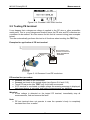
1
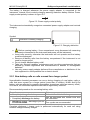
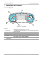
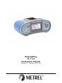
PolarityPlus MI 3106 Instruction manual Version 1.7, Code No. 20 751 133 For sales, service and calibration contact: Emona Instruments Pty Ltd Tel 1 800 652 953 Fax (02) 9550 1378 Email: [email protected] Web: www.emona.com.au Manufacturer: METREL d.d. Ljubljanska cesta 77 1354 Horjul Slovenia web site: http://www.metrel.si e-mail: [email protected] © 2007, 2008 METREL Mark on your equipment certifies that this equipment meets the requirements of the EC (European Community) regulations concerning safety and electromagnetic compatibility. No part of this publication may be reproduced or utilized in any form or by any means without permission in writing from METREL. 2 MI3106 PolarityPLUS Table of contents 1 Preface ..............................................................................................................4 2 Safety and operational considerations ..........................................................5 2.1 Warnings and notes.........................................................................................5 2.2 Battery and charging .......................................................................................6 2.2.1 New battery cells or cells unused for a longer period ..................................7 2.3 Standards applied............................................................................................8 3 Instrument description ....................................................................................9 3.1 Front panel ......................................................................................................9 3.2 Connector panel ............................................................................................10 3.3 Back panel.....................................................................................................11 3.4 Bottom view ...................................................................................................12 3.5 Display organization ......................................................................................13 3.5.1 Terminal voltage monitor...........................................................................13 3.5.2 Menu line...................................................................................................13 3.5.3 Message field ............................................................................................13 3.5.4 Result field ................................................................................................14 3.5.5 Other messages ........................................................................................14 3.5.6 Sound warnings.........................................................................................14 3.5.7 Help...........................................................................................................15 3.5.8 Backlight and contrast adjustments...........................................................15 3.6 Carrying the instrument .................................................................................15 3.7 Instrument set and accessories .....................................................................17 4 Instrument operation .....................................................................................18 4.1 Function selection..........................................................................................18 4.2 Automatic testing ...........................................................................................18 4.3 Single tests ....................................................................................................19 4.4 Instrument settings ........................................................................................20 4.4.1 Setup for I NEUTRAL ................................................................................20 4.4.2 Initial settings.............................................................................................20 5 5.1 5.2 5.3 5.4 5.5 Measurements ................................................................................................21 Voltage and frequency...................................................................................21 Line impedance .............................................................................................23 Resistance to earth........................................................................................24 I NEUTRAL....................................................................................................25 Testing PE terminal .......................................................................................26 6.1 6.2 6.3 6.4 Maintenance....................................................................................................28 Replacing fuses .............................................................................................28 Cleaning ........................................................................................................28 Periodic calibration ........................................................................................28 Service...........................................................................................................28 7.1 7.2 7.3 7.4 7.5 7.6 Technical specifications................................................................................29 Line impedance .............................................................................................29 Resistance to earth........................................................................................29 N conductor current .......................................................................................29 Voltage and frequency...................................................................................29 Online voltage monitor...................................................................................30 General data..................................................................................................30 6 7 3 MI3106 PolarityPLUS Preface 1 Preface Congratulations on your purchase of the PolarityPLUS instrument and its accessories from METREL. The instrument was designed on basis of rich experience, acquired through many years of dealing with electric installation test equipment. The PolarityPLUS instrument is professional, multifunctional, hand-held test instrument intended for testing of proper connection on entry side of electrical installations in buildings. The following measurements and tests can be performed as unique auto sequence or separately: Voltage and frequency, Line impedance, Resistance to earth, Integrity of N conductor. Large dot matrix display with backlight offers easy reading of results, indications, measurement parameters and messages. Operation is simple and clear – operator does not need any special training (except reading this instruction manual) to operate the instrument. In order for operator to be familiar enough with measurements in general and typical applications it is advisable to read Metrel handbook Measurements on electric installations in theory and practice. The instrument is equipped with all accessories necessary for comfortable testing. It is kept in a soft carrying bag together with all accessories. 4 MI3106 PolarityPLUS Safety and operational considerations 2 Safety and operational considerations 2.1 Warnings and notes In order to reach high level of operator’s safety while carrying out various tests and measurements using the PolarityPLUS instrument, as well as to keep the test equipment undamaged, it is necessary to consider the following general warnings: The symbol on the instrument means »Read the Instruction manual with special care to safety operation«. The symbol requires an action! If the test equipment is used in a manner not specified in this user manual the protection provided by the equipment might be impaired! Read this user manual carefully, otherwise use of the instrument may be dangerous for the operator, for the instrument or for the equipment under test! Do not use the instrument and accessories if any damage is noticed! In case a fuse has blown follow the instructions in this manual to replace it! Consider all generally known precautions in order to avoid risk of electric shock while dealing with hazardous voltages! Do not use the instrument in supply systems with voltages higher than 300 V (line to earth)! A competent authorized person can only carry out service intervention or adjustment procedure! Use only standard or optional test accessories supplied by your distributor! Instrument contains rechargeable Ni-Cd or Ni-MH battery cells. The cells should only be replaced with the same type as defined on the battery placement label or in this manual. Do not use standard alkaline battery cells while power supply adapter is connected to prevent their leaking or even explosion! Hazardous voltages exist inside the instrument. Disconnect all test leads, remove the power supply cable and switch off the instrument before removing battery and fuse compartment cover. Do not connect any voltage source to clamp current input. It is intended only for connection of current clamp with current output. Maximum continuous input current is 300 mA! All normal safety precautions have to be taken in order to avoid risk of electric shock when working on electrical installations! Warnings related to measurement functions Testing PE terminal If phase voltage is detected on the tested PE terminal, stop all measurements immediately and take care the fault is eliminated before proceeding with any activity! 5 MI3106 PolarityPLUS Safety and operational considerations Notes related to measurement functions General Indicator means that the selected measurement cannot be performed because of irregular conditions on input terminals. PASS / FAIL indication is applied to each test. In case that only two of three wires are connected to tested electrical installation, only voltage indication between these two wires is valid. Earth resistance Specified accuracy of tested parameters is valid only if mains voltage is stable during the measurement. Line impedance Specified accuracy of tested parameters is valid only if mains voltage is stable during the measurement. I neutral Use test clamp supplied by Metrel or other with similar characteristics (current output, 1000:1, appropriate measurement range, consider error of test clamp when evaluating measured results)! Specified accuracy of tested parameters is valid only if mains voltage is stable during the measurement. Testing PE terminal For correct testing of PE terminal, the TEST key has to be touched for a few seconds. Make sure of standing on non-isolated support while carrying out the test, otherwise test result may be wrong! 2.2 Battery and charging The instrument uses six AA size alkaline or rechargeable Ni-Cd or Ni-MH battery cells. Nominal operating time is declared for cells with nominal capacity of 2100 mAh. Battery condition is always present on the display when the instrument is turned on. In case the battery is weak, the instrument indicates this as shown in figure 2.1. This indication appears for a few seconds and then the instrument is turned off. Figure 2.1: Discharged battery indication 6 MI3106 PolarityPLUS Safety and operational considerations The battery is charged whenever the power supply adapter is connected to the instrument. Internal circuit controls charging assuring maximum battery lifetime. Power supply socket polarity is shown in figure 2.2. + Figure 2.2: Power supply socket polarity The instrument automatically recognizes connected power supply adapter and controls charging. Symbol: Indication of battery charging Figure 2.3: Charging indication Before opening battery / fuse compartment cover disconnect all measuring accessories connected to the instrument and power off the instrument. Insert cells correctly, otherwise the instrument will not operate and the battery could be discharged. Remove all battery cells from the battery compartment if the instrument is not used for longer period. Do not charge alkaline battery cells! Take into account handling, maintenance and recycling requirements that are defined by related regulations and manufacturers of alkaline or rechargeable batteries! Use only power supply adapter delivered from manufacturer or distributor of the test equipment to avoid possible fire or electric shock! 2.2.1 New battery cells or cells unused for a longer period Unpredictable chemical processes can occur during charging of new battery cells or cells that were unused for a longer period (more than 3 months). Ni-MH and Ni-Cd battery cells are affected to capacity degradation (sometimes called as memory effect). As a result, the instrument operation time can be significantly reduced. Recommended procedure for recovering battery cells: Procedure ¾ Completely charge the battery. Notes At least 14h with in-built charger. Can be performed with normal work with the instrument. ¾ Completely discharge the battery. ¾ Repeat the charge / discharge cycle for Four cycles are recommended. at least two times. Complete discharge / charge cycle is performed automatically for each cell using external intelligent battery charger. 7 MI3106 PolarityPLUS Safety and operational considerations Notes: The charger in the instrument is a pack cell charger. This means that the battery cells are connected in series during the charging. The battery cells have to be equivalent (same charge condition, same type and age). One different battery cell can cause an improper charging and incorrect discharging during normal usage of the entire battery pack (it results in heating of the battery pack, significantly decreased operation time, reversed polarity of defective cell,…). If no improvement is achieved after several charge / discharge cycles, then each battery cell should be checked (by comparing battery voltages, testing them in a cell charger, etc). It is very likely that only some of the battery cells are deteriorated. The effects described above should not be mixed with normal decrease of battery capacity over time. Battery also loses some capacity when it is repeatedly charged / discharged. Actual decreasing of capacity, versus number of charging cycles, depends on battery type. It is provided in the technical specification from battery manufacturer. 2.3 Standards applied The PolarityPLUS instrument is manufactured and tested in accordance with the following regulations: Electromagnetic compatibility (EMC) IEC 61326 Electrical equipment for measurement, control and laboratory use – EMC requirements Class B (Hand-held equipment used in controlled EM environments) Safety (LVD) IEC 61010-1 Safety requirements for electrical equipment for measurement, control and laboratory use – Part 1: General requirements IEC 61010-031 Safety requirements for hand-held probe assemblies for electrical measurement and test IEC 61010-2-032 Safety requirements for electrical equipment for measurement, control, and laboratory use - Part 2-032: Particular requirements for hand-held and hand-manipulated current sensors for electrical test and measurement Functionality IEC 61557 Electrical safety in low voltage distribution systems up to 1000 VAC and 1500 VAC – Equipment for testing, measuring or monitoring of protective measures Part 1 ........... General requirements Part 3 ........... Loop resistance Part 10.......... Combined measuring equipment Other reference standards IEC 60364-4-41 Electrical installations of buildings Part 4-41 ...... Protection for safety – protection against electric shock 8 MI3106 PolarityPLUS Instrument description 3 Instrument description 3.1 Front panel 3 4 2 5 6 1 Figure 3.1: Front panel Legend: 1 ON / OFF 2 3 4 Rotary switch LCD HELP 5 TEST 6 BACKLIGHT, CONTRAST Switches the instrument power on or off. The instrument automatically turns off 15 minutes after the last key was pressed. Selects test function. 128 x 64 dots matrix display with backlight. Accesses help menus. Initiates measurements. Acts also as the PE touching electrode. Changes backlight level and contrast. 9 MI3106 PolarityPLUS Instrument description 3.2 Connector panel 2 1 3 4 Figure 3.2: Connector panel Legend: 1 Test connector 2 Charger socket Measuring inputs / outputs, connection of measuring cables. Connection of power supply adapter. Protects from simultaneous access to test connector and power 3 Protection cover supply adapter socket plus communication connectors. 4 Clamp connector Measuring input for current clamp. Warnings! Maximum allowed voltage between any test terminal and ground is 300 V! Maximum allowed voltage between test terminals is 500 V! Maximum short-term voltage of external power supply adapter is 14 V! Do not connect any voltage source on clamp connector sockets! It is intended for connection of current clamp with current output only. Maximum continuous current of current clamp input is 300 mA! 10 MI3106 PolarityPLUS Instrument description 3.3 Back panel 3 2 1 Figure 3.3: Back panel Legend: 1 2 3 Battery / fuse compartment cover Back panel information label Fixing screws for battery / fuse compartment cover 1 2 - Fuse F2 F3 Fuse S/N XXXXXXXX SIZE AA SIZE AA SIZE AA SIZE AA SIZE AA + SIZE AA 3 4 5 Figure 3.4.: Battery and fuse compartment Legend: 1 2 3 4 Fuse F2 Fuse F3 Serial number label Battery cells T 4 A / 500 V T 4 A / 500 V Size AA, alkaline / rechargeable NiMH or NiCd 11 MI3106 PolarityPLUS 5 Battery holder Instrument description Can be removed from the instrument 3.4 Bottom view 2 3 1 Voltage, frequency U: 0V 440V f: 45Hz 65Hz Earth resistance RL-P E : 0.00 19999 Nominal voltage: 100VA C Line impedance RL-N (L) : 0.00 1999 Nominal voltage: 100V AC 27 0VAC / 45Hz 65Hz 270V AC / 45Hz N current IN: 0 1 00 % Figure 3.5: Bottom view Legend: 1 2 3 Bottom information label Neck belt openings Handling side covers 12 65Hz MI3106 PolarityPLUS Instrument description 3.5 Display organization Menu line Result field Message field Terminal voltage monitor Figure 3.6: Typical single test display 3.5.1 Terminal voltage monitor The terminal voltage monitor displays current voltages present on the test terminals. Online voltage is displayed for right polarity of terminals. L and N test terminals are changed. L and PE are test terminals are changed. See the warning below! Warning! Phase voltage on the PE terminal! Stop the activity immediately and eliminate the fault / connection problem before proceeding with any activity! L – N polarity changed. Notes: L = Active line. N = Neutral line. PE = Protective earth. 3.5.2 Menu line In the menu line, the name of the selected function and optional limit value is displayed. Function name. Limit value. 3.5.3 Message field In the message field, different warnings and messages are displayed. Measurement is running; consider displayed warnings. Conditions on the input terminals allow starting the measurement (TEST key); consider other displayed warnings and messages. 13 MI3106 PolarityPLUS Instrument description Conditions on the input terminals do not allow starting the measurement (TEST key), consider displayed warnings and messages. Instrument is overheated, the temperature inside the instrument is higher than the safety limit, and measurement is prohibited until the temperature decreases under the allowed limit. Battery capacity indication. Low battery. Battery is too weak to guarantee correct result. Replace or recharge the battery cells. Recharging in progress (if power supply adapter is connected). 3.5.4 Result field Measurement result is inside limits (PASS). Measurement result is out of limits (FAIL). Measurement is aborted. Consider displayed warnings and messages. 3.5.5 Other messages High wires resistance I NEUTRAL warning: test current < 4A or line impedance > 20 Ω. Hard Reset Instrument settings are reset to initial (factory) values. CAL ERROR! Service intervention required. 3.5.6 Sound warnings Short sound Long sound Periodic sound Pressed key activated. Measurement has been started after pressing the TEST key. Consider any displayed warnings during measurement. Measurement is prohibited. Consider any displayed warnings and check online voltage/terminal monitor! Warning! Dangerous voltage on the PE terminal is detected. Refer to chapter 5.8 for more information. 14 MI3106 PolarityPLUS Instrument description 3.5.7 Help Key: Opens help screen. HELP The help menus contains basic schematic / connection diagram to illustrate recommended connection of the instrument. Figure 3.7: Help screen 3.5.8 Backlight and contrast adjustments With the BACKLIGHT key backlight and contrast can be adjusted. Toggle backlight intensity level. Click Keep pressed for 3 s LCD contrast adjustment menu is displayed. Figure 3.8: Contrast adjustment menu Keys for contrast adjustment: Backlight Help TEST Reduces contrast. Increases contrast. Accepts new contrast. Note: Contrast menu can only be entered in the low intensity backlight state. 3.6 Carrying the instrument With the neck-carrying belt supplied in standard set, various possibilities of carrying the instrument are available. Operator can choose appropriate one on basis of his / her operation. The instrument can be used even placed in soft carrying bag – test cable connected to the instrument through the front aperture. 15 MI3106 PolarityPLUS Instrument description 3.6.1 Mounting of carrying straps Carrying straps shall be mounted to the instrument properly that enables good tightening. The strap is made of materials that slides and do not secure tightening. Following figures show principle for mounting of the straps. 1. insert strap through opening of the instrument 2. Lead strap through 1st opening in fixing plate 2. Lead strap through 2nd opening in fixing plate 3. Tie-up and return strap through 1st opening 4. Tie-up and time to time check fixing Note: The best fixing is application without fixing plate but with secure knots, as they are required in alpine climbing for securing of Nylon knot. 16 MI3106 PolarityPLUS Instrument description 3.6.2 Instrument set and accessories Instrument Measuring accessories*) Documentation Battery CD-ROM Optional accessories*) PolarityPLUS – MI 3106 Soft carrying bag Soft carrying neck belt Soft carrying back belt Universal test cable (3 × 1.5 m) 3 alligator clips (black) Earthing probe Probe test lead 4 m Current clamp Short instruction manual Product verification data Warranty declaration Declaration of conformity 6 Ni-MH rechargeable cells Power supply adapter Instruction manual Short instruction manual Measurement on electric installations in theory and practice Fast 12 cells charger (C and AA sizes) Fast 6 cells charger (AA size) Please, see the attached sheet to compare received set of accessories with listed one. See also the attached sheet for a list of optional accessories that are available on request from your distributor. *) 17 MI3106 PolarityPLUS Instrument operation 4 Instrument operation 4.1 Function selection The instrument contains rotary switch intended for selection of working function. Automatic test (see 4.2), Single tests (see 4.3). Figure 4.1: Rotary switch options 4.2 Automatic testing The rotary switch in position AUTO SEQUENCE is intended for automatic executing of predefined measurement sequence. Auto sequence indication. Sequence field. Message field with battery condition indicator. Figure 4.2: Auto sequence screen Running auto sequence: Select AUTO SEQUENCE. Connect the instrument to tested object as required. Press the TEST key. The set of measurements will be performed in sequential manner until the conditions at input terminals are valid for each individual test. If not, the instrument will stop and abort the rest of sequence. Results of a finished auto sequence can be viewed. Measurements are marked with one of the following symbol after finished test. or Measurement is finished and has failed. or Measurement is finished and has passed. Overall PASS result is reported if all performed tests pass. Overall FAIL result is reported if one or more performed tests fail. 18 MI3106 PolarityPLUS Instrument operation Figure 4.3: Overall PASS example Figure 4.4: Overall FAIL example Viewing auto sequence individual results: After finished auto sequence rotate rotary switch knob to see results in full details for each function in the auto sequence. Running any of the single test function finishes viewing of the results. Note: I NEUTRAL function can be disabled, see, chapter 4.4 for additional information. Figure 4.5: Example of auto sequence with I NEUTRAL disabled 4.3 Single tests They are intended to run individual test / measurement functions and provide more information than the auto sequence screen. They are suitable for pre-testing, troubleshooting, etc. Figure 4.6: Example of typical Single test screen Single test functions can be selected by rotary switch. Selects test / measurement function: Rotary switch TEST <VOLTAGE> Voltage and frequency. <Z-LINE> Line impedance. <R EARTH> Resistance to earth. <I NEUTRAL> Portion of current in neutral conductor. Runs selected test / measurement function. Limits are fixed and intended for evaluation of measurement / test result. See Chapter 5 for more information about operation of the instrument in single test functions. 19 MI3106 PolarityPLUS Instrument operation 4.4 Instrument settings Most settings of the instrument are fixed; operators can enable/disable I NEUTRAL function. 4.4.1 Setup for I NEUTRAL The function I NEUTRAL can be disabled or enabled. I NEUTRAL ON OFF Function enabled. Function disabled. Figure 4.6: Setup for I NEUTRAL Opening SETUP menu: BACKLIGHT key and rotary switch They have to be activated at the same time. Key: TEST Toggles between ON and OFF. Closing SETUP menu: Rotary switch Changing position, new setup is applied. 4.4.2 Initial settings Initial values of instrument settings, measurement parameters and limits are as follows: Instrument settings Contrast Default value 50 % Function VOLTAGE Parameter: limit values Ul-n low limit: 215 V Ul-n high limit: 270 V Un-pe high limit: 5 V Un-pe high limit: < Ul-n Limit: 1 Ω Limit: 10 kΩ Limit: 50 % LINE RESISTANCE TO EARTH I NEUTRAL 20 MI3106 PolarityPLUS Measurements 5 Measurements Main intention of the instrument is to test the integrity of distribution electricity supply connection to a consumer’s installation in one step. For this purpose the connection diagram of required test set-up is as follows. Service fuse or main switch open act ive Utility side ply p Su L bar neutra l Consumer side PE MEN N bar link bar Independent earth Main earthing Figure 5.1: Recommended measuring circuit Single functions are mainly intended to repeat measurements if the problem with one of tested parameters arise. Note: The PASS limit values from chapter 4.4 correspond for main purpose of the instrument, testing connections at house installation entry point. The limits and PASS/FAIL indication are void in single tests applied for other purposes. 5.1 Voltage and frequency Voltage and frequency measurement is always active in the terminal voltage monitor. In the Voltage function the measured voltages and frequency are displayed. In this function, the instrument can be used as a standard 3-terminal V-meter. It automatically detects three-phase supply system. See 4.3 Single test for keys functionality. Figure 5.2: Voltage measurement 21 MI3106 PolarityPLUS Measurements Optional connections for voltage measurement PE/L3 L/L1 N/L2 L/L PE/L3 L1 L2 L3 N PE 1 N/L2 N Ro PE L RE Figure 5.3: Voltage measurement Voltage measurement procedure Select the VOLTAGE function. Connect test cable to the instrument. Connect test leads to the tested object (see figure 5.3). Press the TEST key to run measurement (optional). Figure 5.4: Examples of voltage measurements in single- and three-phase systems Displayed results for single phase system: Ul-n..........Voltage between phase and neutral conductors, Ul-pe........Voltage between phase and protective conductors, Un-pe ......Voltage between neutral and protective conductors, f ...............Frequency. Displayed results for three-phase system: U1-2 ........Voltage between phases L1 and L2, U1-3 ........Voltage between phases L1 and L3, U2-3 ........Voltage between phases L2 and L3, Ph............Phase sequence (1.2.3 – CW rotation sequence; 2.1.3 – CCW rotation sequence), f ...............Frequency. 22 MI3106 PolarityPLUS Measurements 5.2 Line impedance Line impedance is measured in loop comprising of mains voltage source and line wiring (L and N). The measurement is performed according to the IEC 61557-3 standard. In this function the instrument can be used as standard line / loop impedance tester. See 4.3 Single test for keys functionality. Figure 5.5: Line impedance Optional connection for measurement of line impedance L1 L2 L3 N PE PE/L3 L/L 1 N/L2 N Ro PE L RE Figure 5.6: Line impedance measurement Line impedance measurement procedure Select the Z-LINE function. Connect test cable to the instrument. Connect test leads to the tested object (see figure 5.6). Press the TEST key. Figure 5.7: Example of line impedance measurement result Displayed results: Z ..............Line impedance, Lim ..........Maximum value of line impedance. Note: High fluctuations of mains voltage can influence the measurement results. 23 MI3106 PolarityPLUS Measurements 5.3 Resistance to earth The resistance to earth is measured by fault loop resistance procedure. The function can be applied on TT supply systems in the installation before protection devices. See 4.3 Single test for keys functionality. Figure 5.8: Resistance to earth Optional connection for measurement of resistance to earth L1 L2 L3 N PE L/L1 N/L2 PE/L3 Ro RE Figure 5.9: Example for resistance to earth measurement Resistance to earth measurement procedure Select the EARTH function. Connect test cable to the instrument. Connect test leads to the tested object (see figure 5.9). Press the TEST key. Figure 5.10: Example of earth resistance measurement result Displayed result: R..............Resistance to earth. Notes: High fluctuations of mains voltage can influence the measurement results. Applicable in TT systems with earth resistance higher than 500 Ω. 24 MI3106 PolarityPLUS Measurements 5.4 I NEUTRAL The function is intended to calculate the relative portion of total active (line) current that is returned into utility neutral conductor. See 4.3 Single test for keys functionality. Figure 5.11: Example of line impedance measurement result Measurement principle Z line A Iactive Uac Load Z neutral Ineutral MEN R earth1 Active current entering into consumers installation is split into returned neutral and PE current. The neutral current depends on impedance ratio of Zneutral/(Rearth+Rearth1). N IPE PE R earth Figure 5.12: Neutral current measurement principle I NEUTRAL measurement procedure Select the I NEUTRAL function. Connect test cable and clamp current transformer to the instrument. Connect test leads and clamp current transformer to the tested object (see figure 5.1). Press the TEST key. Figure 5.13: Example of N current measurement result Displayed result: I ...............Part of current that is returned to N (neutral) conductor. Notes: Use test clamp supplied by METREL or distributor only! I NEUTRAL function can be disabled, see, chapter 4.4 for additional information. 25 MI3106 PolarityPLUS Measurements Figure 5.14: Disabled I NEUTRAL function 5.5 Testing PE terminal It can happen that a dangerous voltage is applied to the PE wire or other accessible metal parts. This is a very dangerous situation since the PE wire and PE collectors are considered to be earthed. An often reason for this fault is incorrect wiring (see examples below). The user automatically performs this test in all functions when touching the TEST key. Examples for application of PE test terminal L1 N PE Reversed phase and protection conductors! PE/L3 N/L2 L/ L1 N MOST DANGEROUS SITUATION! PE L Figure 5.14: Reversed L and PE conductors PE terminal test procedure Connect test cable to the instrument. Connect test leads to the tested object (see figures 5.14 and 5.15). Touch PE test probe (the TEST key) for at least one second. If PE terminal is connected to phase voltage the warning message is displayed, instrument buzzer is activated, and further measurements are disabled. Warning: If line voltage is detected on the tested PE terminal, immediately stop all measurements, find and remove the fault! Note: PE test terminal does not operate in case the operator’s body is completely insulated from floor or walls! 26 MI3106 PolarityPLUS Measurements In new or adapted installations it may occur that the PE conductor is reversed with the phase conductor – this is a very dangerous situation! This is why it is important to test for the presence of phase voltage at the PE protection terminal. The test is performed before tests where mains supply voltage is applied to the instrument circuitry or before installation is used. 27 MI3106 PolarityPLUS Maintenance 6 Maintenance 6.1 Replacing fuses There are two fuses under back cover of the Polarity instrument. F2, F3 F 4 A / 500 V, 32×6.3 mm General input protection fuses of test terminals L and N. Warnings: Disconnect any measuring accessory and power off the instrument before opening battery/fuse compartment cover, hazardous voltage inside! Replace blown fuse with original type only, otherwise the instrument may be damaged and/or operator’s safety impaired! Position of fuses can be seen in figure 3.4 in chapter 3.3 Back panel. 6.2 Cleaning No special maintenance is required for the housing. To clean the surface of the instrument use a soft cloth slightly moistened with soapy water or alcohol. Then leave the instrument to dry totally before use. Warnings: Do not use liquids based on petrol or hydrocarbons! Do not spill cleaning liquid over the instrument! 6.3 Periodic calibration It is essential that the test instrument is regularly calibrated in order technical specification listed in this manual can be guaranteed. We recommend an annual calibration. An authorised technical person should do the calibration only. Please contact your dealer for further information. 6.4 Service For repairs under warranty, or at any other time, please contact your distributor. Unauthorised person is not allowed to open the instrument. There are no user replaceable components inside the instrument, except the fuses, refer to chapter 6.1 Replacing fuses. 28 MI3106 PolarityPLUS Technical specifications 7 Technical specifications 7.1 Line impedance Measuring range according to EN61557-3 is 0.25 Ω ÷ 19.9 Ω. Accuracy Measuring range (Ω) Resolution (Ω) 0.01 0.00 ÷ 19.99 ±(5 % of reading + 5 digits) Pass value: ...................................................... ≤1.00 Ω Test current (at 230 V)..................................... ca. 7 A Nominal voltage range..................................... 100 V ÷ 270 V (45 Hz ÷ 65 Hz) 7.2 Resistance to earth Measuring range (kΩ) 0.50 ÷ 19.99 20.0 ÷ 49.9 Resolution (Ω) 0.01 0.1 Accuracy ±(5 % of reading + 2 digits) Pass value: ...................................................... ≤10.00 kΩ Test current (at 230 V / RE = 10kΩ) ................ ca 20mA Nominal voltage range..................................... 100 V ÷ 270 V (45 Hz ÷ 65 Hz) 7.3 N conductor current Measuring range (%) 0 ÷ 100 Resolution (%) 1 Accuracy ±(5 % of reading + 3 digits) Pass value: ...................................................... ≥50% Maximum continuous input current .................. 300 mA (=300 A @ current clamp with ratio 1000:1) Overall test current (at 230 V).......................... ca. 7 A Nominal frequency........................................... 45 Hz ÷ 65 Hz Additional clamp error has to be considered. 7.4 Voltage and frequency Given accuracy is valid for all displayed voltages. Measuring range (V) Resolution (V) 1 0 ÷ 500 Accuracy ±(2 % of reading + 2 digits) Nominal frequency range................................. 0 Hz, 45 Hz ÷ 65 Hz Measuring range (Hz) 45.0 ÷ 65.0 Resolution (Hz) 0.1 Pass values: • Active to Neutral voltage: > 215 V • Active to Neutral voltage: < 270 V • Neutral to Earth voltage < 5 V 29 Accuracy ± 2 digits MI3106 PolarityPLUS • Technical specifications Neutral to Earth voltage less than Active to Earth voltage 7.5 Online voltage monitor Measuring range (V) 0 ÷ 500 Resolution (V) 1 Accuracy ±(2 % of reading + 2 digits) Nominal frequency range................................. 0 Hz, 45 Hz ÷ 65 Hz 7.6 General data Power supply voltage........................ 9 VDC (6×1.5 V battery cells, size AA) Power supply adapter ....................... 12 V ÷ 14 V / 400 mA Battery charging current ................... < 250 mA (internally regulated) Operation.......................................... typical 50 h Overvoltage category........................ CAT IV / 300 V Protection classification .................... double insulation Pollution degree................................ 2 Protection degree ............................. IP 42 Display ............................................ 128×64 dots matrix display with backlight Dimensions (w × h × d) ..................... 23 cm × 10.3 cm × 11.5 cm Weight (without battery).................... 1.21 kg Reference conditions Reference temperature range ...... 10 ºC ÷ 30 ºC Reference humidity range ............ 40 %RH ÷ 70 %RH Operating conditions Working temperature range.......... 0 ºC ÷ 40 ºC Maximum relative humidity ........... 95 %RH (0 ºC ÷ 40 ºC), non-condensing Storage conditions Temperature range ........................ -10 ºC ÷ +70 ºC Maximum relative humidity............. 90 %RH (-10 ºC ÷ +40 ºC) 80 %RH (40 ºC ÷ 60 ºC) The error in operating conditions could be at most the error for reference conditions (specified in the manual for each function) + 1 % of measured value + 1 digit unless otherwise specified. 30