1
dot User’s Manual, December 22, 2009
1
2
Basic Graph Drawing
dot draws directed graphs. It reads attributed graph text files and writes drawings,
either as graph files or in a graphics format such as GIF, PNG, SVG, PDF, or
PostScript.
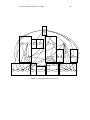
dot draws graphs in four main phases. Knowing this helps you to understand
what kind of layouts dot makes and how you can control them. The layout procedure used by dot relies on the graph being acyclic. Thus, the first step is to break
any cycles which occur in the input graph by reversing the internal direction of
certain cyclic edges. The next step assigns nodes to discrete ranks or levels. In a
top-to-bottom drawing, ranks determine Y coordinates. Edges that span more than
one rank are broken into chains of “virtual” nodes and unit-length edges. The third
step orders nodes within ranks to avoid crossings. The fourth step sets X coordinates of nodes to keep edges short, and the final step routes edge splines. This is
the same general approach as most hierarchical graph drawing programs, based on
the work of Warfield [War77], Carpano [Car80] and Sugiyama [STT81]. We refer
the reader to [GKNV93] for a thorough explanation of dot’s algorithms.
dot accepts input in the DOT language (cf. Appendix D). This language describes three main kinds of objects: graphs, nodes, and edges. The main (outermost) graph can be directed (digraph) or undirected graph. Because dot makes
layouts of directed graphs, all the following examples use digraph. (A separate
layout utility, neato, draws undirected graphs [Nor92].) Within a main graph, a
subgraph defines a subset of nodes and edges.
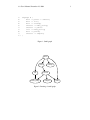
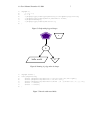
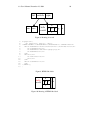
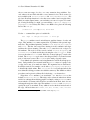
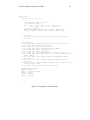
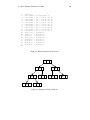
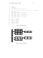
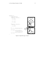
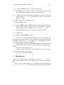
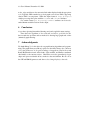
Figure 1 is an example graph in the DOT language. Line 1 gives the graph
name and type. The lines that follow create nodes, edges, or subgraphs, and set
attributes. Names of all these objects may be C identifiers, numbers, or quoted C
strings. Quotes protect punctuation and white space.
A node is created when its name first appears in the file. An edge is created
when nodes are joined by the edge operator ->. In the example, line 2 makes
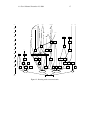
edges from main to parse, and from parse to execute. Running dot on this file (call
it graph1.dot)
$ dot -Tps graph1.dot -o graph1.ps
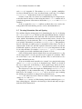
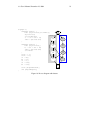
yields the drawing of Figure 2. The command line option -Tps selects PostScript
(EPSF) output. graph1.ps may be printed, displayed by a PostScript viewer, or
embedded in another document.
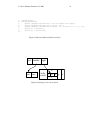
It is often useful to adjust the representation or placement of nodes and edges
in the layout. This is done by setting attributes of nodes, edges, or subgraphs in
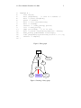
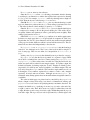
the input file. Attributes are name-value pairs of character strings. Figures 3 and 4
illustrate some layout attributes. In the listing of Figure 3, line 2 sets the graph’s