1
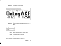
Dolog AKF125 → A120/A250 Type: AKF125EN Version: 7.10 Installation User Instruction DOK–702082.35–1096 Translation of the German Description DOK–700565.35–0196 Accompanying software package E-No. 424-275182 Documents in the software package Kit 1 Documentation Installation User Instruction DOK-702082 Explains the usage and installation of the diskette s included. How do you proceed? User Instruction DOK-702084 Serves as a ”red thread” through the documentation of the software packet and should be gone over before the start. Kit 2 Documentation AKF125 for Beginners User Instruction DOK-702083 Area of application Serves to introduce new customers to AKF125. The user learns how to use the software in samll steps. Short Form Guide A120 User Instruction DOK-702087 Tables for validity ranges and symstem markers, SFB-Formal operands for quick use onsite. Sort Form Guide A250 User Instruction DOK-702088 Tables for validity ranges and symstem markers, SFB-Formal operands for quick use onsite. Configuration A120 User Instruction DOK-702085 35 Area of application Contains the new features of the current version and explains th efunctions of th individual software menus for the configurer. Documents in the software package iii Kit 3 Documentation Configuration A250 (Vo1) User Instruction DOK-702086 Configuration A250 (Vo2) User Instruction DOK-707695 Masterindex User Instruction DOK-702089 iv Area of application Contains the new features of the current version and explains th efunctions of th individual software menus for the configurer. The explanation of the individual software menus will continued. Index of all documentation. Documents in the software package 35 Notes Application Note Caution The relevant regulations must be observed for control applications involving safety requirements. For reasons of safety and to ensure compliance with documented system data, repairs to components should be performed only by the manufacturer. Training Schneider Automation GmbH offers suitable training that provides further information concerning the system (see addresses). Data, Illustrations, Alterations Data and illustration are not binding. We reserve the right to alter our products in line with our policy of continuous product development. If you have any suggestions for improvements or amendments or have found errors in this publication, please notify us by using the form on the last page of this publication. Addresses The addresses are given at the end of this publication. 20 v Copyright All rights reserved. No part of this document may be reproduced or transmitted in any form or by any means, electronic or mechanical, including copying, processing or any information storage, without permission in writing by the Schneider Automation GmbH. You are not authorized to translate this document into any other language. Trademarks All terms used in this user manual to denote Schneider Automation GmbH products are trademarks of the Schneider Automation GmbH. 1996 Schneider Automation GmbH. vi 20 Terminology Note This symbol emphasizes very important facts. Caution This symbol refers to frequently appearing error sources. Warning This symbol points to sources of danger that may cause financial and health damages or may have other aggravating consequences. Expert This symbol is used when a more detailed information is given, which is intended exclusively for experts (special training required). Skipping this information does not interfere with understanding the publication and does not restrict standard application of the product. Path This symbol identifies the use of paths in software menus. Figures are given in the spelling corresponding to international practice and approved by SI (Système International d‘ Unités). I.e. a space between the thousands and the usage of a decimal point (e.g.: 12 345.67). 20 vii Abbreviatons ABS Adr. AE AZ AKF ALD ALS AWL AWP BGT BSS DAE DAZ DIB DB0....9 DPB DSB DW I/O FB FUP FW HW IB KB KF KFW KOP KS LZS MW OB PB PaDT RK SFB SK viii absolute Adressing Adresse (signal adresse) Block for one time actions Block for cyclicel actions Instructionlist, Contaktplan, Functionlist Sequentiel Flow Chart with Diagnostics Sequentiel Flow Chart Instructionlist User programm Subrack Serviceconnection for PC ore VS210 Diagnostics Block for one time actions (AE) Diagnostics Block for cyclicel actions (AZ) Diagnostics Block for Block independent Diagnostics SYM/KOM-Datablock for A120 Diagnostics Block for Programm Blocks (PB) Diagnostics Structure Block Double word Input– / Output signales (e.g. from a Module) Function block Function list Floatingpoint Hardware (z.B. PLC) Initial value block Sequentiel block Sequentiel errorbit Sequentiel errorword Kontaktplan Kettenstatus für Simultankette Run Time System Markerword Organisations Block Program Block Programming- and Diagnostics testequipment Controlloop Standard-Function Block Step marker 20 SM Systemmarker SSP Signal memory SW Software SYM symbolic Adressing SYM/COM Symbol und Comment SZ Step Counter TB Transitionsblock TN Teilnehmer VBGT Virtuelle Subrack (InterBus-S, Modnet 1/IS)) ZVT Time organiasationtable (Controlle) ZZ Time Counter <Return> Applay the key Return <Esc> Applay the key Esc <Ctrl>+<Alt>+<Applay in the same time the keys Ctrl, Alt und Del (beginning with Ctrl.and finnishing with Del) 20 ix Objectives The installation instructions are used to install this configuration software and communication driver on the PaDT. Arrangement of this guide x Chapter 1 Introduction Chapter 2 Selecting the programming panels and the hardware/software requirements. Chapter 3 Installing the configuration software and the communication driver. 33 Related Documents A250 User Manual A250 804 BHB 000 00 A250 User Manual A250 Regeln mit Dolog AKF 804 BHB 001 00 A250 User Manual A250 Prozessperipherie Frontanschlusstechnik 899 BHB 000 00 A250 User Manual A250 Cable 899 BHB 001 00 A250 Blockbibliothek Standard Funktionblocks A250 Vol. 1 (AKF125 V4.x, ALD25 V4.1) 804 BSB 001 00 A250 Blockbibliothek Standard Funktionblocks A250 Vol. 2 (AKF125 V4.x, ALD25 V4.1) 804 BSB 002 00 20 xi Validity Note These User Instructions apply to the AKF125 software, version 7.1, on the DOS operating system. The current intention is for remote control data only to be edited with the AKF125 configuration software and not with ALD25. Therefore, within systems U250 and UZ250, remote control modules KOS140, KOS141 and DEZ161 should not be used as REAL–TIME variants. Correspondingly, the KOS 20x modules of the U120, Z120 and UZ120 systems are not to be used. xii 20 Table of Contents Chapter 1 Introduction . . . . . . . . . . . . . . . . . . . . . . . . . . . . . 1 Chapter 2 Prerequisites of AKF125 . . . . . . . . . . . . . . . . . 3 2.1 2.1.1 2.1.2 2.1.3 2.2 Panel Selection/Prerequisites . . . . . . . . . . . . . . . . . . . . . . . . 4 Important Notes . . . . . . . . . . . . . . . . . . . . . . . . . . . . . . . . . . . . 4 Prerequisites of Programming Panels . . . . . . . . . . . . . . . . . 5 DOS Prerequisites . . . . . . . . . . . . . . . . . . . . . . . . . . . . . . . . . 6 Generating a backup copy . . . . . . . . . . . . . . . . . . . . . . . . . . . 8 Chapter 3 Installation . . . . . . . . . . . . . . . . . . . . . . . . . . . . . . 9 3.1 3.1.1 3.1.2 3.1.3 3.1.4 3.2 Index 35 install software . . . . . . . . . . . . . . . . . . . . . . . . . . . . . . . . . . . Installation of the AKF125 software . . . . . . . . . . . . . . . . . Installation of the Communication Driver . . . . . . . . . . . . Deinstallation . . . . . . . . . . . . . . . . . . . . . . . . . . . . . . . . . . . . End . . . . . . . . . . . . . . . . . . . . . . . . . . . . . . . . . . . . . . . . . . . . Calling the Software DOLOG AKF A120/A250 . . . . . . . 10 10 12 14 14 15 . . . . . . . . . . . . . . . . . . . . . . . . . . . . . . . . . . . . . . . 17 Table of Contents xiii xiv Table of Contents 35 Chapter 1 Introduction 33 Introduction 1 1.1 Overview The present publication describes the installation of the Modicon software packages. The software is valid for IBM-compatible personal computers running under the MS–DOS operating system, and in particular for IBM-compatible programming panels from AEG Schneider Automation. The software installation of Modicon Software is menu-driven. This ensures that user files installed previously cannot be destroyed. Even if you already have the operating system installed, we advise you to set up the personal computer with this software on Modicon Software (for computers with hard disks) Note: Programming panels will from now on be called PaDT (Programming and Debugging Tool). You can use your PaDT, together with the available software, to program the A250 programmable controller. The programs can be compiled, logged and archived with the help of the programming panel. You can also use EPROM programming panels (EPS 2000) to program EPROMs. 2 Introduction 33 Chapter 2 Prerequisites of AKF125 In this chapter you will learn about the prerequisites for programming panel selection and for the hardware and software. Note: For features of the software packages please see the Modicon catalogues for the programmable controllers. 33 Prerequisites of AKF125 3 2.1 Panel Selection/Prerequisites 2.1.1 Important Notes Note: Optimum operation is guaranteed by the panels P510-40 (from panel index .03), P610 (from panel index .03), P610C, P810 P820C, P840C. From this index the programming panels are supplied from stock with memory upgrade installed (incl. driver installation). You will find the panel index on the silver plate (underneath the panel), marked Rev. Caution: MS-DOS versions 3.3 or higher: The MS-DOS command APPEND may not be used in connection with this software, or the APPEND command must not lead to AKF directories. Caution: Do not start any memory–resident or interrupt–controlled PC programs in parallel with this project software (memory utilization too great). Caution: Remember the DOS–specific incompatibility of files created with the backup command (applies to DOS version 5.0 or higher). 4 Prerequisites of AKF125 33 2.1.2 Prerequisites of Programming Panels The programming panels offered by ASAD in its price lists. These panels are IBM-AT compatible PCs with the features shown below: Hard disk (e.g. 70 MByte) 3 1/2 ” (1.44MB) diskette drive file CONFIG.SYS in accordance with chapter 2.1.3 at least 4 MByte RAM, of which not used main memory (MS-DOS) before calling up AKF125: at least 590 KByte no memory–resident programs started on the PaDT MS-DOS version 5.0 or higher COM1 for operating the PLC on the PaDT (for uploading the program, initial start–up) COM2 optional, for connecting a mouse or a printer (for configuration, documentation, monitoring) LPT1 optional, for connecting a printer (for configuration, documentation, monitoring) 33 Prerequisites of AKF125 5 2.1.3 DOS Prerequisites For this software to function reliably on the PC the following points must be observed: The system file CONFIG.SYS contains the following entries: DEVICE=C:\DOS\HIMEM.SYS DEVICE=C:\DOS\EMM386.EXE 2048 RAM x=C800-CFFF DOS=HIGH,UMB FILES=30 BUFFERS=20 COUNTRY=049,437,C:\DOS\COUNTRY.SYS DECIVEHIGH=C:\DOS\SMARTDRV.SYS 1024 512 DEVICEHIGH=C:\DOS\ANSI.SYS To reach a useful working speed, the run–time system of AKF125 needs add–on memory to LIM EMS 3.2 or 4.0 incl. 64 KByte page frame (RAM), as entered above. The expanded memory (EMS) should be at least 256 KB in size. Further increases in speed can be reached by expansion by up to 2 MB. Any expansion beyond 2 MB will not be used by AKF125. Note: For using COMAKF a memory area is reserved for the interface module (BIK003). This area is dependent on the address specified on the BIK. The available areas are: C800 - CFFF (as supplied), D000 - D7FF and D800 - DFFF This reservation is performed in a line of file CONFIG.SYS. Example of a BIK address C800 (as shipped) DEVICE=C:\DOS\EMM386.EXE 2048 RAM x=C800-CFFF This reservation is performed automatically when the BIK is installed. However, if the address of the BIK is modified subsequently, the entry in the file must be modified accordingly. 6 Prerequisites of AKF125 33 Caution: On PCs with 486 processors only BIK 003 driver version > 2.10 is allowed. These drivers can only be used on IBM-AT PCs, XT-PCs are not supported. The system file AUTOEXEC.BAT contains the following entries: @ ECHO OFF PATH C:\;C:\DOS PROMT $P$G SET TEMP=C:\TMP LH C:\DOS\KEYB UK,,C:\DOS\KEYBOARD.SYS LH DOSKEY VER REM C:\DOS\DOSSHELL Note: A German or a British keyboard can be used for AKF125. The appropriate keyboard driver must be loaded to correspond to the keyboard layout. The driver is activated in the file AUTOEXEC.BAT. The British keyboard driver is loaded in the specimen files. If the German keyboard driver is to be loaded the entry ”...KEYB UK,,C:\....” must be replaced by ”...KEYB GR;;C:\...”. 33 Prerequisites of AKF125 7 2.2 Generating a backup copy A backup can be made of every original diskette included in the software package. To do so the required number of blank diskettes (corresponding to the number of original diskettes) should be kept available. Once you are in the operating system, proceed as follows: Step 1 Type ”Diskcopy a: a:”. Step 2 Follow the instructions on the screen. Step 3 Answer the question ”Make further copies (Y/N)?_” with ”Y” until all the original diskettes have been copied. Note: Label the backup copies to match the original diskette(s). Store the original diskettes in a safe place. Make sure that the data cannot be destroyed. 8 Prerequisites of AKF125 33 Chapter 3 Installation In this chapter you will learn about the installation of AKF125 and the communication driver. 35 Installation 9 3.1 install software The software and the communication driver are installed using the prepared bakkup copies. Note: Nothing needs to be deleted to overwrite an old software version with a more recent one. The old files are automatically overwritten by the command ”A:INSTALL”. Note: Please do not work on the originals but instead first create backup copies, see Chapter 3.2. 3.1.1 Installation of the AKF125 software Step 1 Make sure that your programming panel meets all the requirements stated in chapter 2.1. Step 2 If you have modified the files CONFIG.SYS or AUTOEXEC.BAT, reset the PaDT with a <Ctrl>+<Alt>+<Del> (”warm restart”) Response 10 The user drive message is displayed (e.g. C:\) Step 3 Insert diskette #1 in the diskette drive Step 4 Enter A:INSTAL and <Return> (A: here stands for the letter of your diskette drive) Step 5 Enter the drive into which you have inserted the program diskette (default A:) and confirm with <Return>. Installation 35 Response Step 6 Response The installation program prompts Open the installation menu with <Return> The selection window software/driver opens, the bar is on AKF125. Step 7 Start the software installation by pressing <Return> Step 8 |Follow the instructions on the screen. Step 9 If you do not want to install any driver, move the bar to End with <³> and press <Return>. You can now call the configuration software (cf. Chapter 4.4). 35 Installation 11 3.1.2 Installation of the Communication Driver Note: For AKF125 you can currently install a driver for the Modnet 1/SFB network with BIK 003. Only one driver can be active at a time. If a second driver is installed the first driver will be overwritten.The driver installation may be done separately from the software installation. Caution: For PCs with 486 processors (e.g. P810, P820C) only BIK 003 driver version > 2.10 is allowed. These drivers can only be used on IBM-AT PCs, XT PCs are not supported. If you install the software and the driver directly after each other, start with Step 2. 12 Step 1 Insert the diskette supplied with your BIK module in the diskette drive Step 2 Enter A:INSTAL and <Return> (A: here stands for the letter of your diskette drive) Step 3 Enter the drive into which you have inserted the program diskette (default A:) and confirm with <Return>. Step 4 Open the installation menu by pressing <Return> Step 5 Move the menu bar onto ”Communication Driver” with the arrow keys and press <Return> Step 6 Follow the instructions on the screen. The following texts discuss the parameter settings Installation 35 After confirmation that you want to use Modnet 1/SFB, the following window is displayed: BIK 003 You can choose between communication controller type: BIK 003* Dualport RAM address: C800*, D000, D800 user-interrupt 60, 61, 62*, 63, 64 * shows the menu default settings If you do not want to use C800 as the dualport address during installation, then you must also modify the bridges to the BIK module (cf. the appropriate module description). Step 7 Set the parameters to the required settings by selecting the lines with the arrow keys and toggling with <Return> (the line with the menu bar is always modified) Step 8 Move the menu bar to ”Confirm entry” and press <Return> Step 9 Move the menu bar to ”End” with the arrow keys and confirm with <Return> Note: The file CONFIG.SYS is automatically modified. You can now call the configuration software (cf. Chapter 4.4). 35 Installation 13 3.1.3 Deinstallation After pressing <Return> the following window is displayed: The deinstallation functions delete the software files on your programming panel. Your systems and stations are not affected. 3.1.4 End This menu item is used to leave the installation program after completing installation. You can terminate software installation at the specified points by pressing <Esc>. In which case, the user diskette drive prompt will immediately return (e.g. C:\). 14 Installation 35 3.2 Calling the Software DOLOG AKF → A120/A250 Start the software at MS-DOS level (see Table 1, page 15). Table 1 Starting the Software Entry AKF125 AKF125 AKF125 AKF125 AKF125 Recommendation for monitor <Return> /COL<Return> /BW<Return> /GY<Return> /NOSPS<Return> – Colour monitor Liquid Crystal Display and Plasma Monitor Monochrome monitor applies to operation of the mouse on port COM1 Note: After installation you will be in the configuration section of A250. To run A120 the ALU type must first be changed (cf. user instructions ”How do I proceed?”, Chapter 1). 35 Installation 15 16 Installation 35 Index A Append, 4 P Panel Selection, Software-Installation, 4 B Backup Copy, Software-Installation, 8 C calling the software, 15 D Deinstallation, 14 Driver, Installation, 12 S Software, Installation, 10 software, call, 15 Software-installation, overview, 2 W warm restart, 10 I Installation, Software, 10 35 Index 17 18 Index 35