1
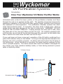
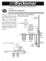
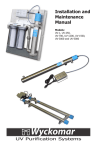
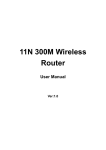
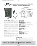
Installation and
Maintenance
Manual
Models:
UV-1, UV-250,
UV-700, UV-1200, UV-1500,
UV-3000, UV-5000 and UV-6000
UV Purification Systems
CAUTION - WARNING
The ballast and all electrical connections MUST
be mounted and installed ABOVE the water lines
to prevent the possibility of electrical shock in
case of a water leak.
See “Safety Precautions” on Page 4
Please read this entire User Manual
before attempting to install your UV system.
Read and follow ALL safety precautions
Keep this manual in a safe place
for future reference.
Unit Serial Number:
Date of Purchase:
Please keep your sales receipt as proof of purchase for warranty purposes.
Copyright
Copyright by Wyckomar Inc. 2014. No part of this manual may be reproduced or transmitted in any
form without the expressed, written permission of Wyckomar Inc.
Notice
Although Wyckomar has attempted to ensure the accuracy of the content of this manual, it is possible
that this document may contain technical inaccuracies, typographical, or other errors. Wyckomar assumes no liability for any error in this publication, and for damages, whether direct, indirect, incidental,
consequential or otherwise
Wyckomar provides this publication “as is” without warranty of any kind, either expressed or implied.
Use of the system is at the discretion of the buyer.
The published information in this manual is subject to change without notice. Wyckomar reserves the
right to make changes in the product design and layout without notification to its customers.
UV Purification Systems
Introduction
Congratulations on purchasing a Wyckomar UV purification system. Please read
through the installation procedures and follow all safety warnings when setting
up your system. Wyckomar Inc. manufactures several sizes of UV purification systems; however, they all operate on the same principle. Basic installation is the
same for most units. Refer to the exploded view diagrams for replacement parts.
Table
of Contents
Page
Section 1 - Introduction
How Ultraviolet Water Purification Works
How Your Wyckomar UV Water Purifier Works
2
3
Section 2 - Setting Up
Safety Precautions
Important Considerations
Installation Diagrams
Installation
Start Up Operation
4
5
6
7
8
Section 3 - Maintenance
Disinfecting Your Water System
Ultraviolet Lamp Replacement
Quartz Dome or Sleeve Replacement / Cleaning
Changing Filter Cartridges
Filter Maintenance and Troubleshooting
Troubleshooting Guide
Section 4 - Technical Info
Exploded Diagrams and Parts Lists
9
10
11
12
13
22
14 - 21
Section 5 - Accessories
Filter Sets and Cartridges
UV Monitoring System
Remote Output and Operation Logging
Purge Valve, Hour Meter
23
24
25
26
Section 6 - Contact and Warranty
Wyckomar Contact Info
Warranty Registration Card
27
28
1
UV Purification Systems
Introduction
How Ultraviolet Water Purification Works
Wyckomar Ultraviolet (UV) Purifiers utilize the proven principle of ultraviolet light
radiation to eliminate or reduce unacceptable levels of microorganisms in water
and other liquids. Ultraviolet light energy destroys bacteria, viruses, fungi, spores,
algae and other such contaminants, which are pathogenic to humans, animals and
plants.
Ultraviolet purification is a completely natural, non-chemical, environmentally safe
technique, which adds nothing to, and removes nothing from the water (such as
trace minerals).
Factors Affecting UV Purification
The Wyckomar UV Purifier is guaranteed to eliminate microbiological contamination only if the physical qualities of the influent water supply are as follows:
Turbidity (Suspended Solids): Turbidity must be < 1.0 NTU at the time of disinfection. There must be a 5-micron or less sediment prefiltration system installed
before the UV system.
TDS (Total Dissolved Solids): Should not exceed approximately 500 ppm.
Total Hardness (Sum of Calcium & Magnesium): Must be < 10 gpg (grains per
gallon) of hardness, otherwise pretreatment is required.
Tannins & Colour: Must be < 2.0 ppm, or pretreatment is required.
Iron: Must be < 0.3 ppm.
Manganese: Must be < 0.05 ppm.
If your water quality parameters do not meet these criteria,
please contact the manufacturer for pretreatment recommendations.
2
UV Purification Systems
Introduction
How Your Wyckomar UV Water Purifier Works
Untreated water enters the lower portion of the purification chamber and flows
through the unit in an upward circular path. The spiraling movement assures the
maximum irradiation of the fluid and helps prevent larger particles from blocking
the treatment of microorganisms. The purification chamber contains the ultraviolet light-producing lamp. In operation, the lamp emits a bluish glow, which is
visible in the view port window on the side of some units. WARNING: DO NOT
LOOK AT THE UV LIGHT DIRECTLY. Looking through the view port is safe, since
the glass disc in the view port filters out the UV rays. On systems equipped with
a UV monitor, do not look at the UV light through the view port, as the quartz disc
that is used in this case does not filter out the UV rays.
If your unit does not have a view port, operation of the UV light is confirmed by a
green LED indicator lamp on the ballast. As long as the appropriate indicators are
glowing, the unit is working properly. An alarm will sound when the UV lamp is
not functioning. When the alarm is sounding, the lamp must be replaced for the
unit to operate properly. The alarm sounds also when the ballast is damaged for
any reason (e.g. from moisture buildup inside, or from having received a power
spike or lightning strike).
To Power Source
Treated water OUT
UV Lamp
Untreated water IN
3
UV Purification Systems
Setting Up
Safety Precautions
Please READ and FOLLOW all safety precautions.
SAVE these instructions.
Never expose your eyes directly to UV light.
This UV system is designed for indoor use only. Do not use this UV system where
it may be exposed to the elements. Protect the unit from freezing at all times.
ELECTRICAL SHOCK HAZARD
This UV system is installed near water. Please take all necessary precautions.
Other than where noted in this manual, DO NOT attempt to repair parts yourself,
but contact the manufacturer or authorized dealer for repair service.
The electronic ballast in this system can get damaged from voltage and/or frequency deviations, caused by power outages or lightning strikes. Only connect
this UV system to a properly grounded outlet. A GFCI circuit is recommended.
It should not be plugged into the same circuit as a water pump, since the on/off
cycle of the pump can cause voltage spikes in the line.
It is highly recommended, especially in rural areas, to install a quality voltage
regulator or surge suppressor, rated at > 3600 Joules at the power input
to the ballast.
In older homes, the installation of plastic water treatment devices such as filter
housings may interrupt the water pipe’s electrical continuity to ground. This can
lead to pinhole leaking due to electrolysis or stray current corrosion. For prevention, the piping has to be properly bonded and grounded. Contact a professional
plumber for information.
Ensure installation is in compliance with all local laws, regulations and codes.
DO NOT operate the UV system if the power cord, plug or any electrical component appears to be damaged or if the unit has been dropped or damaged in any
way. Inspect the UV system after installation, and carefully check for leaks. DO
NOT plug in the system if there is water on any part(s) that are not intended to
be wet.
This system is to be used ONLY for its intended use of potable water disinfection.
DO NOT use attachments that are not approved by the manufacturer, as this may
cause problems with the UV system.
4
UV Purification Systems
Setting Up
Important Considerations
Wyckomar purifiers are installed either at the main water supply line or at point
of use. In some installations, particularly where plumbing is old, the water may
become re-contaminated in the pipes between the purifier and the faucet. Be sure
to follow instructions under “Disinfecting Your Water System” on Page 9
Wyckomar purifiers are designed to be installed vertically and work best when
mounted in this position. However, in cases with space restrictions, the unit may
be mounted horizontally (see Installation Diagrams on Page 6).
Important: Clearance to the side or above the unit for lamp exchanges
should be equal to the length of the purifier.
Caution: The ballast and all electrical connections must be mounted and installed above water lines to prevent the possibility of electric shock in the case
of a water leak. A grounded electrical outlet is required (GFCI is preferred).
The manufacturer’s warranty is only applicable when prefiltered water is used.
Prefilters (to 5 micron) remove sediment particles that can reduce the effectiveness of the UV lamp or potentially damage the unit.
If a water softener, iron removal system or other treatment device is installed or
planned for, your purifier should be located closest to the faucet.
Install your Wyckomar purifier indoors in a protected area. The temperature should
not fall below 4 ˚C (40 ˚F). Avoid conditions with high humidity to prevent condensation on the purification chamber. Ideal temperature conditions range from
9 ˚C to 29 ˚C.
Use Teflon tape (T-tape) liberally on all pipe connections (3 turns around the fitting). Do not use any other sealants other than food grade pipe dope.
Use food-grade silicon or plumber’s grease on O-rings. DO NOT use oil-based
products.
5
UV Purification Systems
Setting Up
Installation Diagrams
Wyckomar systems can be
installed vertical or horizontal. Refer to these sche–
matic drawings for typical
position of components.
Ensure that there is adequate clearance at the lamp
end of the unit in order to
safely remove the UV lamp
from the chamber. Space
required for clearance is at
least the length of the UV
chamber.
6
UV Purification Systems
Setting Up
Installation
Carefully select the location for the UV system and any related components. Note
the direction of water flow in the supply line to which the unit is being connected.
Refer to the appropriate exploded view diagram for your unit and check to see that
you have all the necessary fittings.
Parts List: 4 screws
1 quartz dome or sleeve, 1 or 2 O-rings
1 alcohol wipe 1 Allen key wrench
1 UV lamp w/ O-rings on each end
Turn off the main water supply valve. Fasten unit to wall, using the mounting clips
(”pipe hangers”) and screws provided. Press the UV chamber into the clips for a
secure hold.
Install new plumbing, making sure the In and Out ports on the filter set point in
the direction of water flow. Installation of bypass and valves is recommended.
Install filter set
Install UV unit
After installation of the plumbing is
complete, install electrical components
(surge suppressor and ballast, monitor if
present) ABOVE the water line.
Complete installation with pre-filter set and UV.
Inlet/Outlet shutoff valves are recommended.
7
UV Purification Systems
Setting Up
Installation and Start Up Operation
Take the plastic cap off the unit and remove the black nut from the end of the
unit. Remove quartz sleeve/dome from packaging, being careful not to loose the
spring inside the dome. You may wish to lubricate o-ring with food-grade silicon
or plumber’s grease (do NOT use oil based products such as Vaseline) and roll it
over one end of the sleeve or the open end of the dome. Avoid fingerprints on the
sleeve/dome, wipe with alcohol.
Gently slide the sleeve/dome into the unit. For domed systems (UV-1, UV-250,
UV-700 and UV-1200), the dome will center itself inside the bottom of the reaction chamber. For sleeved systems (UV-1500, UV-3000, UV-5000 and UV-6000),
the sleeve(s) will protrude out of the reaction chamber at the bottom end, hold in
place with hand or foot. Roll second o-ring over the end at the bottom.
Thread on the compression nut(s). The O-ring will set itself into the beveled seal
of the bushing on the reaction chamber. Hand tighten the nut(s) (do NOT use
tools). In sleeved systems, install the lower plastic cap and gently tighten the set
screws with the Allen key supplied. This will keep the lamp from sliding through.
Insert the UV lamp, it will center itself in the spring inside the dome in domed systems, or stop at the lower plastic cap in sleeved systems. Connect the white 4-pin
electrical connector. Replace the top plastic cap and gently tighten setscrews.
Unit is now ready to be turned on.
Open main water valve slowly. As water fills into the filter set, press the red button on top of the first filter housing (pressure relief valve) to release air. Hold until
water starts to escape and then release. Continue with next filter. Open valves
on either side of purifier slowly and check for leaks (bypass valve should remain
closed). Turn on any faucet to release air in the system, wait for a steady stream
of water, then turn off faucet.
Plug the power cable from the ballast into an appropriate power source outlet (a
power surge suppressor rated at> 3600 Joules is strongly recommended). Wait for the lamp to come on (up to 30 sec) and inspect the ballast and
viewport, if present.
Now that system is operating properly, any incoming water is disinfected. Any exisiting pathogens downstream of the system, if present, are not affected. Therefore, it is mandatory to disinfected the plumbing system downstream
from the unit after installation according to the instructions on Page 9.
8
UV Purification Systems
Setting Up / Maintenance
Disinfecting Your Water System
In any UV system, disinfection takes place inside the UV chamber and there is no
residual disinfection agent remaining in the water stream. Pathogens that may still
be present in the plumbing system downstream of the UV unit will not be affected
by the disinfection process. For this reason, it is CRITICAL that the plumbing
system is disinfected after initial installation to prevent possible re-contamination
of the water on it’s way to the taps.
The following steps must be taken to accomplish this important task.
1T
urn off the water supply to the UV unit and make sure that the by-pass valve is
closed if equipped. Turn on the UV unit.
2R
emove the filter bowls from the filter housing head and remove the filter cartridges.
3F
ill one filter bowl one-half full with chlorine bleach and screw the bowls (without
cartridges) back onto the filter housing head.
4T
urn on the water supply, check for leaks.
5T
urn on every tap in the water system of the building both inside and outside,
one-by-one. Run the water at each tap until the smell of chlorine is evident. Let
the system sit idle for 60 minutes.
6W
hile the UV lamp remains on, open all taps in the water system to flush out the
chlorine - approximately 5 minutes.
7W
hen all chlorine is flushed from the system, and while the UV lamp remains on,
shut off the water supply and reinstall the filter cartridges in the filter housings.
8T
urn on the water supply, check for leaks. Test water for contaminants.
WARNING
This simple procedure must be performed after installation
of the UV system, and whenever the UV system is shut down
or inoperative for any reason whatsoever.
9
UV Purification Systems
Maintenance
Ultraviolet Lamp Replacement
The UV lamp located in the purification chamber will operate effectively for approximately 1 year (9000 hours) under normal conditions. The lamp will still light
after that period, but maximum UV light intensity may fall below the prescribed
safety level.
Important:
It is required that the lamp be changed every 12 months after installation regardless of apparent condition of the lamp. For warranty purpose use only
original manufacturer replacement parts.
Caution! Do not look directly at the UV.
1U
nplug the purifier from the electrical outlet. Note: It is not necessary to turn
off the water supply. Do not use water.
2 W
ith the Allen key provided, loosen the two set screws that secure the top cap
containing the electrical cord. Remove the cap and carefully set aside (it is attached to the ground wire).
3 R
emove the lamp connector located at the cord end of the lamp by gently wiggling and pulling away from the lamp.
4 C
arefully slide the UV lamp out of the quartz dome/sleeve and discard appropriately.
5 I nsert the replacement lamp into the quartz dome/sleeve. Hold lamp at ceramic
ends. Do not touch the lamp with your hands - fingerprints will prevent the system from working properly. If the lamp is touched, clean with an alcohol wipe.
6 G
ently push the lamp connector against the pins at the end of the new lamp.
7 M
ake sure that all electrical components are dry before replacing the top cap.
Secure the cap with the setscrews.
8 P
lug in the power cord. The lamp should be operating at this time. To confirm
that your new lamp is working correctly, check your model’s light indicator on
the ballast and, if present, check the view port.
10
UV Purification Systems
Maintenance
Cleaning/Replacing the Quartz Dome or Sleeve
Important:
If water turbidity is a problem, it is advisable to clean the quartz dome/sleeve
each time when replacing the lamp.
1 T
urn off the water supply and open a faucet to depressurize the plumbing system. Unplug the purifier from the electrical outlet. Press the pressure-relief
button on one of the filter housings. Horizontal mounted systems need to be
drained by removing filter bowls. Have a bucket on hand.
2 W
ith the Allen key provided, loosen the two set screws that secure the top cap
containing the electrical cord. Remove the cap and carefully set aside (it is
attached to the chamber with the ground wire).
3 R
emove the white lamp pin connector from lamp end. Remove the UV lamp
carefully from the UV unit.
4 Loosen
and remove the sealing compression nut. Caution: Quartz dome/
sleeve may be stuck to the O-ring inside the retaining nut.
5 Carefully remove the quartz dome/sleeve from the UV chamber.
6 W
ipe the quartz dome/sleeve with nonabrasive cleaner (e.g. CLR or Limeaway)
and with an alcohol wipe being careful not to touch the dome/sleeve with your
fingers. You may choose to lubricate the O-ring with food-grade silicon or
plumber’s grease (do not use oil based products, such as Vaseline). Slide the
O-ring onto the dome/sleeve.
7 U
sing a clean cloth to hold the end of the replacement quartz dome/sleeve,
guide it gently into the UV chamber and screw the sealing compression nut
down until snug to secure seal. Hand-tight only, DO NOT USE TOOLS!
8 I nsert the replacement lamp into the quartz dome/sleeve. Gently push the
lamp pin connector against the pins at the end of the lamp.
9 C
omplete the reassembly of the UV purifier. Make sure that all electrical parts
are dry before replacing the top cap and securing it with the setscrews.
10 Plug in the ballast, turn on the water supply and check for leaks.
11
UV Purification Systems
Maintenance
Changing Filter Cartridges
Filter cartridges have to be changed on a frequent basis to ensure porper operation of the system. A pressure drop detected at the tap is an indication that the
sediment filter cartridges is at capacity, and a re-occurrence of unwanted taste or
odour is an indication that the carbon cartridge (if present) is exhausted.
Follow these steps to change out filter cartridges in your system.
1 T
urn off the water supply. If isolation valves are installed at the unit, close them
both.
2 Depress
pressure release button to relieve pressure in filter housing. Unscrew
housing with plastic wrench. Note: When opening filter housing, it is common
for the O-ring/gasket to lift out of the housing and stick to cap.
3 Remove
used cartridge and discard. Rinse out housing and fill approximately
1/3 full of water. Add about 2 to 3 teaspoons of bleach and scrub thoroughly
with brush or sponge. Rinse thoroughly.
4 R
emove O-ring/gasket from sump and wipe groove and O-ring/gasket clean.
You may choose to lubricate O-ring/gasket with a coating of food grade silicon
grease. Place O-ring/gasket back in place and press O-ring/gasket down into
the groove with fingers (or place on rim of sump). Note: Make sure O-ring/
gasket is seated level to maintain proper seal. If O-ring/gasket appears damaged, replace at this time.
5 I nsert a new cartridge into the sump making sure that it slips down over the
sump standpipe.
6 Screw
the sump onto the cap and handtighten. Make sure that the cartridge
slips over the cap standpipe.
7 O
pen shutoffs at the UV system (if present), open a faucet to depressurize the
plumbing system, then turn on the water supply slowly to allow filter housing(s)
to fill with water.
8 Depress
the pressure release button (if present) to release trapped air from the
filter housings.
9 C
heck for leaks before leaving installation. Filter sump may be gently tightened
with plastic filter wrench if leaks occur. DO NOT OVERTIGHTEN!
12
UV Purification Systems
Maintenance
Filter Maintenance and Troubleshooting
Important:
Do not use filter with water that is microbiologically unsafe or of unknown quality without adequate disinfection before or after the unit.
An activated carbon cartridge (Taste/Odour) may contain a small amount of carbon fines (very fine black powder). A new cartridge should be flushed with sufficient water after installation to remove the fines before using the water.
Each time that you use water from your filtered water tap for drinking or cooking
purposes, it is recommended that you run the tap for at least 10 seconds prior to
using the water. This is important if the water tap is not used daily.
Replacement filter cartridges have a limited service life. Changes in taste, colour
and flow of the water being filtered are signals that replacement of the cartridge
is imminent or may soon be necessary.
CAUTION: The filter must be protected against freezing. Failure to do so may
result in cracking of the filter and water leakage.
CAUTION: All filtration systems contain other parts that have a limited service
life. Exhaustion of the service life of those parts often cannot be easily detected.
Commonly, it is only after leakage has been observed or water damage has occurred that one is made aware that the service life has been exhausted.
IMPORTANT NOTICE: To prevent costly repairs or possible water damage, we
recommend that the bowl or sump of all plastic housings be replaced periodically:
at least every 5 years for clear sumps, and every 10 years for opaque sumps.
13
UV Purification Systems
UV-1
Technical Info
Exploded Diagram & Parts List
Item Part No.
1
2
3
4
5
Description
4-BE-425W-U
10-5
8-51
RL-12/254T5
11-3
Ballast
Set Screw
Quartz Compression Nut
UV Lamp
Quartz Dome Seal 2-211
1
10
11
2
3
5
7
4
6
13
12
8
16
Item Part No.
Description
6
7
8
9
10
11
12
13
14
15
16
Quartz Disc Seal/Lamp O-ring 2-113
Quartz Dome Sleeve 22X25X269
UV-1 Chamber
Lamp Extension Spring
Plastic Cap
Lamp Connector
End Washer
End Bushing
Concave Cap End
Conical Spring
3/8" NPT 316SS Inlet/Outlet Ports
14
11-6
RQD-269
2-1
8-29-1
8-4-1
4-2
8-50
8-52
8-49-1
8-25
8-11
9
16
15
14
UV Purification Systems
UV-250
Technical Info
Exploded Diagram & Parts List
Item Part No.
1
2
3
4
5
4-BE-425W-U
10-5
8-51
RL-23/436T5
11-3
Description
Ballast
Set Screw
Quartz Compression Nut
UV Lamp
Quartz Dome Seal 2-211
1
10
11
2
3
5
7
4
6
13
12
8
16
Item Part No.
Description
6
7
8
9
10
11
12
13
14
15
16
Quartz Disc Seal/Lamp O-ring 2-113
Quartz Dome Sleeve 22X25X438
UV-250 Chamber
Lamp Extension Spring
Plastic Cap
Lamp Connector
End Washer
End Bushing
Concave Cap End
Conical Spring
3/4" NPT 316SS Inlet/Outlet Ports
11-6
RQD-438
2-2
8-29-1
8-4-1
4-2
8-50
8-52
8-49-1
8-25
8-5
9
16
15
14
15
UV Purification Systems
UV-700
Technical Info
Exploded Diagram & Parts List
1
Item
1
2
3
4
5
6
7
8
Part No.
4-BE-425W-U
10-5
8-51
RQD-895
11-3
RL-40/867T5
11-6
8-10
Description
Ballast
Set Screw
Quartz Compression Nut
Quartz Domed Sleeve 22x25x895
Quartz Sleeve Seal 2-211
UV Lamp
Glass Disc Seal/Lamp O-ring 2-113
Viewport Outer Bushing
14
2
15
3
6
4
7
5
17
16
20
11
7
12
10
Item
9
10
11
12
13
14
15
16
17
18
19
20
16
Part No.
7-15GL
8-11
8-9
2-3
8-29
8-4-1
4-2
8-50
8-52
8-49-1
8-25
8-5
9
Description
Glass Viewport Disc
Viewport Inner Bushing
Viewport Compression Nut
UV700 Chamber
Lamp Extension Spring
Plastic Cap
Lamp Connector
End Washer
End Bushing
Concave Cap End
Conical Spring
3/4" NPT 316SS Inlet/Outlet Ports
8
13
20
19
18
UV Purification Systems
UV-1200
Technical Info
Exploded Diagram & Parts List
1
Item
Part No.
Description
1
2
3
4
5
6
7
4-BE-800WL-1/2
10-5
8-51
RQD-895
11-3
RL-84/893T5
11-6
8
8-10
Ballast
Set Screw
Quartz Compression Nut
Quartz Domed Sleeve 22x25x895
Quartz Sleeve Seal 2-211
UV Lamp
Glass Disc Seal/
Lamp O-ring 2-113
Viewport Outer Bushing
14
2
15
3
6
4
7
5
17
16
20
11
7
12
10
9
8
Item Part No. Description
9
10
11
12
13
14
15
16
17
18
19
20
7-15GL
8-11
8-9
2-5
8-29
8-4-1
4-2
8-50
8-52
8-49-1
8-25
8-12
Glass Viewport Disc
Viewport Inner Bushing
Viewport Compression Nut
UV1200 Chamber
Lamp Extension Spring
Plastic Cap
Lamp Connector
End Washer
End Bushing
Concave Cap End
Conical Spring
1.0" NPT 316SS Inlet/Outlet Ports
13
20
19
18
17
UV Purification Systems
UV-1500
Technical Info
Exploded Diagram & Parts List
Item Part No.
4-BE-800WL-1/2
10-5
8-53
8-4-1
4-2
RL-110/1197T5
RQS-1181
1
2
3
4
5
6
7
1
2
4
5
3
8
6
8
11-6
9
10
11
12
11-3
8-52
8-50
8-12
Description
Ballast
Set Screw
Quartz Compression Nut
Large Blue Cap
Lamp Connector
UV Lamp
Quartz Open Sleeve
22x25x1181
Glass Disc Seal/
Lamp O-ring 2-113
Quartz Sleeve Seal 2-211
End Bushing
End Washer
1.0” NPT 316SS
Inlet/Outlet Ports
12
7
8
13
9
14
16
15
17
Item
13
14
15
16
17
18
19
18
Part No.
8-9
8-10
8-11
7-15GL
2-4
5-2
8-4
Description
Viewport Compression Nut
Viewport Outer Bushing
Viewport Inner Bushing
Glass Viewport Disc
UV1500 Chamber
Mounting Feet
Small Blue Cap
18
8
12
9
3
11
10
19
UV Purification Systems
UV-3000
Item
1
2
3
4
5
6
7
Part No.
4-BE-800WL30-1/2
10-5
8-40
8-301
11-10
RL-100/1197T6
RQS-1190
8
9
10
11-324
8-30
8-302
Technical Info
Exploded Diagram & Parts List
Description
Ballast
Set Screw
Black End Cap
Quartz Compression Nut
Lamp O-ring 19x6
UV Lamp
Quartz Open Sleeve
32x36x1190
Quartz Sleeve Seal 2-324
End Flange
Threaded End Bushing
2
3
19
1
2
6
7
4
5
8
11
13
12
14
16
17
18
11
15
9
10
5
3
8
4
Item
11
12
13
14
15
16
17
18
19
Part No.
8-28
8-10
7-15GL
8-9
5-3
11-6
8-11
2-30
4-2
Description
1-1/2" NPT 316 SS Inlet/Outlet Ports
Viewport Outer Bushing
Glass Viewport Disc
Viewport Compression Nut
Mounting Feet
Glass Disc Seal/Lamp O-ring 2-113
Viewport Inner Bushing
UV3000 Chamber
Lamp Connector
19
UV Purification Systems
UV-5000
Item
1
2
3
4
5
Part No.
4-BE-800WL-1/2
10-5
8-53
RL-110/1197T5
11-6
6
7
11-3
RQS-1181
8
9
2-6
8-11
Technical Info
Exploded Diagram & Parts List
Description
Ballast
Set Screw
Quartz Compression Nut
UV Lamp
Quartz Disc Seal/
Lamp O-ring 2-113
Quartz Sleeve Seal 2-211
Quartz Open Sleeve
22X25X1181
UV5000 Chamber
Viewport Inner Bushing
1
12
1
2
2
12
3
in newer UV-5000 Systems,
the view port assemblies are
located on top of the chamber
4
5
15
6
7
16
15
8
17
9
10
11
6
3
19
20
14
13
5
Item
5
Part No. Description
10
11
12
13
14
15
16
17
18
19
8-9
8-10
8-4-1
8-52
8-50
8-14
2-4
7-15GL
5-2
8-4
Viewport Compression Nut
Viewport Outer Bushing
Large Blue Cap
End Bushing
End Washer
2" NPT316SS inlet/oulet Ports
Chamber Joiner Tube
Glass Viewport Disk
Mounting Feet (not pictured)
Small Blue Cap
UV Purification Systems
UV-6000
Item
1
2
3
4
5
6
7
Part No.
4-BE-800W30L-1/2
10-5
8-301
RL-100/1197T6
11-10
11-324
RQS-1190
8
9
2-60
8-11
Technical Info
Exploded Diagram & Parts List
Description
Ballast
Set Screw
Quartz Compression Nut
UV Lamp
Lamp O-ring 19x6
Quartz Sleeve Seal 2-324
Quartz Open Sleeve
22X25X1190
UV6000 Chamber
Viewport Inner Bushing
1
12
1
2
3
in newer UV-6000 Systems,
the view port assemblies are
located on top of the chamber
12
5
15
4
7
6
16
15
8
17
9
10
11
5
6
3
12
14
13
5
Item
Part No. Description
10
11
12
13
14
15
16
17
18
8-9
8-10
8-40
8-302
8-50
8-28
2-7
7-15GL
5-3
Viewport Compression Nut
Viewport Outer Bushing
Black End Cap
End Bushing
End Washer
1.5" NPT316SS inlet/oulet Ports
Chamber Joiner Tube
Glass Viewport Disk
Mounting Feet (not pictured)
21
22
Leak at quartz sleeve
UV Lamp will not light
Trouble
Replace
Check that indicator light is
on
Check output voltage
Check that white lamp end
connector is secure on
lamp pins
Lubricate or replace O-ring
Defective UV Lamp
Defective Lamp Ballast
Defective or cracked O-ring
Replace quartz sleeve
Check or replace
Breaker/fuse has blown
Quartz fracture
Check or replace
Line cord disconnected or
outlet defective
Replace O-ring
Install a voltage regulator
Input voltage below or
above 120/240 volts
O-ring not seated properly
Solution
Cause
UV Purification Systems
Maintenance
Troubleshooting Guide
If problem persists, call Wyckomar Inc. for technical assistance.
1.800.419.5162 or 519.822.1886 email [email protected]
UV Purification Systems
Accessories
Filter Sets and Cartridges
Filter Sets are available in standard 10” and 20” configurations, in SlimLine and
BigBlue sizes. For commercial applications with higher flow rates, stainless steel
filter housings are available. We HIGHLY recommend a 5 micron sediment and a
carbon filter be installed ahead of the UV unit in order to ensure proper UV operation. Commercial grade filter systems for higher flow rates are also available.
Sediment and carbon filter cartridges are available from Wyckomar. Other types of
filter cartridges for the removal of various contminants are also available (arsenic,
fluoride, etc). Minerals and dissolved solids have an effect on the clarity of the
water and therefore on the efficacy of the UV disinfection process. If elevated
levels of these contaminants are present, additional equipment may be needed to
reduce/remove them from the water. Please refer to the Section ”Factors affecting
UV Purification” on Page 2.
Be sure to replace filter cartridges on a regular basis to ensure proper operation of
your UV disinfection system.
Filter Cartridges
10” Filter Set
SlimLine
20” Filter Set
SlimLine
20” Filter Set
BigBlue
Filter Housings for
UV-5000 and UV-6000
23
UV Purification Systems
Accessories
UV Monitoring System
A Wyckomar UV Monitor (available separately) measures true UV intensity at 254
nm, which is the effective germicidal wavelength for UV treatment of drinking water. It continuously monitors lamp output inside the reaction chamber through a
sensor in the viewport, regardless of whether or not water is flowing through the
system. UV intensity is constantly displayed in real-time on the meter face on the
monitor device. If the UV intensity emitted by the lamp drops below the alarm
set-point (70% of new lamp UV output), the audible alarm will sound. An optional
solenoid valve may be connected to the monitor to stop the water flow.
The UV Monitor is available with volt-free contacts for remote signaling of operation, and also with 4-20mA output for remote operation logging (see Page 25).
Installation instructions are supplied with the UV Monitor.
24
UV Purification Systems
Accessories
Remote Output and Operation Logging
An electronic ballast and a monitor can be equipped with volt-free contacts to allow remote signalling of the operation. This allows to incorporate the UV system
into the work-flow of a large water treatment system that is centrally operated
through a BMS (building management system).
A UV Monitor with 4-20 mA output for remote operation logging in a PLC is also
available.
UV Monitor with 4-20 mA Output
UV Monitor Wet/Dry Contacts Extension
25
UV Purification Systems
Accessories
Purge Valve, Hour Meter
Thermo-Sensitive Purge Valve
During times of no-flow, some UV systems will warm up, as there is no cool water
flowing through the chamber to cool the lamp. This is normal.
Increased temperature of the water means reduced UV output, as hot lamps do
not produce as much germicidal output as cool lamps do. This may result in the
UV system going into alarm state, if it is equipped with a UV Monitor.
The solution to this problem is to install a thermo-sensitive purge valve at the out
port of the UV system. It will automatically open and drain water from the chamber, to allow cool water to replace it and maintain high UV output of the lamp. No
power is required.
Purge Valve
Installation on the Out Port with a T-Fitting
Hour Meter
The electronic ballast of any Wyckomar UV system can be equipped with an optional resettable hour meter, displaying the total run time of the lamp. This is
convenient for ensuring that the lamp is not used after the germicidal output has
decreased to less than 70% of the output of a new lamp (after 9000 hours of
operation).
Ballast with Hour Meter
Installed
26
UV Purification Systems
Contact and Warranty Information
Congratulations on purchasing a Wyckomar UV purification system. We want you
to be satisfied with your product and with our service. If you need to contact
a Wyckomar Customer Service Representative, please have your product model
number and serial number ready.
For warranty service, please contact us for an RMA number and ship defective
product, along with proof of purchase indicating the date of purchase and a letter
describing the problem, to:
Mail:
Wyckomar Inc.
111 Malcolm Road
Guelph, Ontario, CANADA
N1K 1A8
Telephone:
Fax:
1.800.419.5162
519.822.1886
519.763.6580
Email:
[email protected]
Web Site:
www.wyckomaruv.com
For this warranty to be effective, when making a warranty claim you must
include your proof of purchase receipt indicating the date of purchase
Wyckomar Inc. warrants to the first purchaser of the UV unit that the UV reactor chamber will be free
from faulty material and/or workmanship for a period of 5 years from date of purchase. Ballasts, UV
Monitors and UV Lamps carry a one-year pro-rated warranty from date of purchase.
Wyckomar Inc.’s liability during the warranty period is limited to the repair and/or replacement of the
part(s), which prove to be defective in material and/or workmanship under normal use. Shipping,
handling and service costs are the responsibility of the purchaser. The defective part or unit must be
returned to Wyckomar at the purchaser’s expense.
The warranty is not transferable and is the only warranty authorized by Wyckomar Inc. Any other warranty or guarantee, implied or offered, will not be honored by Wyckomar Inc.
This warranty is void, if in the opinion of Wyckomar Inc. that the product failure was caused by misuse,
abuse, accident or improper installation. Do not install systems out of doors (in the elements). All units
are for indoor use only in a dry location.
As a result of this warranty, Wyckomar Inc. is not responsible for any damages, injuries or losses
whatsoever, including those incurred during installation, repair or replacement, as well as incidental or
consequential damages.
27
UV Purification Systems
Warranty Registration Card
Please fill out your Wyckomar Product Registration Card and return it to the manufacturer. Alternatively, you may email the information to [email protected]
or fill the form out online at www.wyckomaruv.com/Warranty.html
Last Name
First Name
Street Address
City
Province/State
Postal Code/Zip
Phone Number
Country
Date of Purchase
email Address
Product Model Number
Product Serial Number
Purchased From
This unit is installed
28
in a residential building
in a commercial business
on a municipal water supply
on a private well
Wyckomar
means
chemical-free
Wyckomar Inc. has been manufacturing
Chemical-Free Ultra Violet
Water Purification and Filtration Systems
since 1978
Currently, we sell our products in more than
25 countries around the globe. Our products are very
environmental-friendly by reducing or eliminating the
need for chemical-based water disinfection systems.
For information on distribution opportunities, including
our internet affiliate network, please contact our sales
department.
[email protected]
http://www.wyckomaruv.com
111 Malcolm Road
Guelph, Ontario
Canada N1K 1A8
Ph. ++1-519-822-1886
Fx. ++1-519-763-6580
www.wyckomaruv.com
[email protected]
0914