Download Settings - School of Electrical and Computer Engineering

Transcript
© 2003 Evolution Robotics, Inc. All rights reserved. Evolution Robotics and the Evolution
Robotics logo are trademarks of Evolution Robotics, Inc.
®
Microsoft DirectX is a trademark of Microsoft Corporation.
®
Microsoft Speech SDK 5.1 is a trademark of Microsoft Corporation.
®
Microsoft Windows is a trademark of Microsoft Corporation.
DirectXTM is a trademark of Microsoft Corporation.
MyWanIpTM is a trademark of Tzolkin Corporation.
XBeamTM is a trademark of XBeams, Inc.
Other product and brand names may be trademarks or registered trademarks of their respective
owners.
Part number MC6023.
Last revised 4/13/03.
IMPORTANT SAFETY INFORMATION
Before using the robot, basic safety precautions should always be followed including the
following:
READ ALL INSTRUCTIONS BEFORE USING
KEEP AWAY FROM WATER
WARNING: IMPORTANT SAFEGUARDS
• To prevent fire or shock hazard, do not expose the robot, the Gripper or the IR sensors
to rain or moisture.
• To avoid electrical shock, do not operate in or near water.
• To avoid breakage or damage to the robot or your laptop computer, use caution in
operating the robot. Do not operate the robot outdoors, near stairs or on top of furniture.
Use the robot on a level surface.
• To avoid damage to property or injury to persons, always operate robot under close
supervision. THE ROBOT SHOULD NEVER BE LEFT TO OPERATE
UNATTENDED OR UNSUPERVISED.
• To reduce risk of damage to your laptop computer, use caution in ensuring that your
laptop computer is securely fastened to the robot. BY USING THE ROBOT WITH
YOUR LAPTOP COMPUTER, YOU ARE ASSUMING ALL RISKS FOR ANY
DAMAGE TO YOUR LAPTOP COMPUTER.
• Do not under any circumstances use the robot to move, touch or handle dangerous or
hazardous materials. Doing this could result in injury or death to the user or damage to
property.
• The robot is not a toy and is not recommended for children.
• Keep hair, loose clothing and all body parts away from openings and moving parts.
• Beware of loose objects that may be caught in the motors or wheels.
• Use the switch on the back of the robot to turn the robot off when you wish to stop the
robot.
• Do not open any of the electrical components housed in sheet metal units, as this might
result in fire or shock hazard.
• Our product parts may contain sharp edges and should be handled with caution to avoid
injury.
• Store packing materials safely out of reach of children to prevent the risk of suffocation
from plastic bags.
• Do not operate the robot near pets.
• Use only as described in this instruction manual.
• Only use the charger provided your ER1.
ER1 User Guide
• Do not plug your laptop charger into the power input in the Robot Control Module
(RCM). This will severely damage your RCM, and may cause a fire.
• The ER1 IR Sensor Kit and the ER1 Gripper Arm are designed for use with the ER1
and should not be used in any manner not expressly approved or recommended by
Evolution Robotics.
• Do not attempt to use the Gripper to grip, carry, and/or release fragile, flammable or
poisonous items, pets, children, or open containers of hot liquid. Extremely fragile
items may be dented or damaged if gripped.
• Releasing objects from the Gripper will cause them to fall. This is an intentional part of
the design, but may cause damage or destruction of the object being released, and/or the
area onto which the object falls. This includes the laptop mounted on the ER1 Robot,
especially if the Gripper is installed so that the pincers are directly over the laptop's
keyboard. BY USING THE ROBOT AND THE GRIPPER ARM WITH YOUR
LAPTOP COMPUTER, YOU ARE ASSUMING ALL RISKS FOR ANY DAMAGE
TO YOUR LAPTOP COMPUTER.
• Similarly, do not rely on the Gripper to maintain an indefinite, secure grip on an object.
Although the Gripper is designed for secure transportation of objects, there is no
guarantee that an object will not slip out of the Gripper.
• Do not attempt to carry items heavy enough to cause the ER1 Robot to tip over. How
much weight the ER1 Robot can hold depends on the configuration of the robot, and
where on the robot the Gripper is installed.
• Use common sense when employing the Gripper. It is possible for the Gripper to pull a
heavy item, such as a bookcase, over onto itself, potentially damaging or destroying the
robot, and/or surrounding items, and injuring humans/pets.
Changes or modifications not expressly approved by the party responsible for compliance
could void the user’s authority to operate the equipment. 47 C.F.R. section 15.21.
Important Note: This equipment has been tested and found to comply with the limits for a
Class B digital device, pursuant to Part 15 of the FCC Rules. These limits are designed to
provide reasonable protection against harmful interference in a residential installation.
This equipment generates, uses and can radiate radio frequency energy and, if not
installed and used in accordance with the instructions, may cause harmful interference to
radio communications. However, there is no guarantee that interference will not occur in a
particular installation. If this equipment does cause harmful interference to radio or
television reception, which can be determined by turning the equipment off and on, the
user is encouraged to try to correct the interference by one or more of the following
measures:
• Reorient or relocate the receiving antenna.
• Increase the separation between the equipment and receiver.
• Connect the equipment into an outlet on a circuit different from that to which the
receiver is connected.
Consult the dealer or an experienced radio/TV technician for help.
ER1 User Guide
DO NOT OPERATE ROBOT
WHILE CONNECTED TO CHARGER
DANGER: Rechargeable Battery Pack
If the rechargeable battery pack is incorrectly replaced, there is a danger of an explosion.
The battery pack contains a small amount of harmful substances. To avoid possible injury:
• Replace only with a battery of the type recommended by Evolution Robotics.
• Keep the battery pack away from fire, water and rain.
• Do not attempt to disassemble the battery pack.
• Ensure that the battery pack is securely fastened to the robot.
• Do not short-circuit the battery pack.
• Keep the battery pack away from children.
When disposing of the battery pack, comply with local ordinances or regulations.
Nothing herein shall constitute a warranty, expressed or implied, including any warranty
of merchantability or fitness. In no event shall Evolution Robotics be responsible for any
special, incidental or consequential damages.
ER1 User Guide
ER1 User Guide
Table of Contents
Chapter 1: Introduction
Robot Control Center Software ................................................................................... 1-2
Possibilities ............................................................................................................... 1-3
New Features ............................................................................................................ 1-4
Customer Support ...................................................................................................... 1-5
Registration ............................................................................................................... 1-5
ER1 Community ........................................................................................................ 1-5
Chapter 2: Getting Started
Robot Specifications .................................................................................................. 2-3
Laptop Requirements ................................................................................................. 2-3
Optional Second Camera ............................................................................................ 2-3
Optional Remote Control ........................................................................................... 2-4
Optional Email .......................................................................................................... 2-4
Trying Out the Software ............................................................................................. 2-4
Making the Robot Count ..................................................................................... 2-5
Making the Robot Move ..................................................................................... 2-7
Chapter 3: Behavior Programming Overview
Behavior Tabs ........................................................................................................... 3-2
Behavior Configurations ............................................................................................ 3-2
Behavior Files .................................................................................................... 3-2
If Conditions ............................................................................................................. 3-3
Sight Condition .................................................................................................. 3-3
Sound Condition ................................................................................................ 3-3
Time Condition .................................................................................................. 3-4
ER1 User Guide
Table of Contents
Message Receive Condition .................................................................................3-4
Sequence Condition .............................................................................................3-4
IR Sensor Condition ............................................................................................3-4
Gripper Condition ...............................................................................................3-4
Then Actions ..............................................................................................................3-4
Move ..................................................................................................................3-5
Play a Sound .......................................................................................................3-5
Run a Program ....................................................................................................3-5
Message Send .....................................................................................................3-5
Record ................................................................................................................3-5
Gripper ...............................................................................................................3-5
Trying Out Actions..............................................................................................3-6
Running and Stopping Behaviors..........................................................................3-6
Behavior Execution .............................................................................................3-6
Behavior Error and Logging ........................................................................................3-8
Chapter 4: Audio, Video and Navigation Controls
Opening the ER1 RCC Software ..................................................................................4-1
Video Display ............................................................................................................4-2
Recognized Objects ....................................................................................................4-2
Obstacle Camera (optional) .........................................................................................4-2
Navigate ....................................................................................................................4-3
Resetting the X, Y coordinates .............................................................................4-3
About X, Y Coordinates ......................................................................................4-3
Remote Operation of the Gripper .................................................................................4-4
Independent Operation of the Gripper ..........................................................................4-5
Recognize Button .......................................................................................................4-5
Speaker Button ...........................................................................................................4-5
Push to Talk ...............................................................................................................4-6
Battery Icon ...............................................................................................................4-6
Closing the ER1 RCC Software ...................................................................................4-6
Example .............................................................................................................4-6
Chapter 5: Function Buttons
New Button ................................................................................................................5-1
Open Button ...............................................................................................................5-2
Save Button ...............................................................................................................5-2
ER1 User Guide
Save Only Active Fields...................................................................................... 5-2
Settings Button .......................................................................................................... 5-3
Help Button ............................................................................................................... 5-4
Remote Control Indicator ........................................................................................... 5-4
Chapter 6: If Conditions
Sight Condition ......................................................................................................... 6-2
Color Selection Tool ........................................................................................... 6-2
Object ................................................................................................................ 6-2
Motion ............................................................................................................... 6-6
Sound Condition ........................................................................................................ 6-6
Time Condition ......................................................................................................... 6-7
A Couple of Tips ................................................................................................ 6-7
Sequence Condition ................................................................................................... 6-8
Message Receive Condition........................................................................................ 6-8
IR Condition ............................................................................................................. 6-10
Gripper Condition ...................................................................................................... 6-10
Chapter 7: Then Actions
Reset and Try It Buttons............................................................................................. 7-1
Move ........................................................................................................................ 7-2
Play a Sound ............................................................................................................. 7-4
Run a Program .......................................................................................................... 7-5
Message Send............................................................................................................ 7-6
Record ...................................................................................................................... 7-6
Gripper ..................................................................................................................... 7-8
Run it Button ............................................................................................................. 7-8
Stop Button ............................................................................................................... 7-8
Chapter 8: Settings
Sight Tab .................................................................................................................. 8-2
Camera Tab ............................................................................................................... 8-3
Device ............................................................................................................... 8-4
Resolution.......................................................................................................... 8-4
Remote Transmission ......................................................................................... 8-4
Sound Tab ................................................................................................................. 8-5
Remote Control Tab................................................................................................... 8-6
ER1 User Guide
Table of Contents
Email Tab ..................................................................................................................8-9
Motion Tab ................................................................................................................8-11
Obstacle Avoidance Tab .............................................................................................8-12
Positioning the Obstacle Avoidance Camera .........................................................8-13
Avoidance Camera Calibration .............................................................................8-14
Avoidance Camera View .....................................................................................8-14
Obstacle Avoidance At Work ...............................................................................8-14
Log Tab .....................................................................................................................8-15
Joystick Tab ...............................................................................................................8-16
About Joystick Control ........................................................................................8-18
Gripper Tab ...............................................................................................................8-19
IR Sensors Tab ...........................................................................................................8-20
IR Sensor Kit Specifications ................................................................................8-22
Using The IR Sensors ..........................................................................................8-23
Push to Talk Tab ........................................................................................................8-24
Display Tab ...............................................................................................................8-26
About Tab ..................................................................................................................8-28
Chapter 9: Behavior Settings
Sight Tab ...................................................................................................................9-1
Image Recognizer................................................................................................9-1
Color Recognizer ................................................................................................9-2
Motion Detection ................................................................................................9-2
Sound Tab .................................................................................................................9-3
Helpful Hints about Grammar Files ......................................................................9-4
Photo Tab ..................................................................................................................9-4
Video Tab ..................................................................................................................9-5
Motion Tab ................................................................................................................9-8
Rotation Angular Velocity ...................................................................................9-8
Motion Linear Velocity .......................................................................................9-9
Motor Power .......................................................................................................9-10
Collision Detection ..............................................................................................9-10
Obstacle Avoidance Tab .............................................................................................9-11
Run Tab .....................................................................................................................9-12
Helpful Hints ......................................................................................................9-14
Examples ............................................................................................................9-14
Joystick Tab ...............................................................................................................9-15
ER1 User Guide
IR Sensors Tab .......................................................................................................... 9-17
Logic Tab ................................................................................................................. 9-18
Load Tab .................................................................................................................. 9-19
Apply This Page to All Behaviors Now ....................................................................... 9-20
Chapter 10: ER1 Command Line Interface
Accessing the API ................................................................................................... 10-2
Telnet Windows XP Setup ....................................................................................... 10-3
Older Windows Telnet Setup .................................................................................... 10-3
Using the Telnet Connection .................................................................................... 10-4
Commands .............................................................................................................. 10-5
Examples ................................................................................................................ 10-5
Command Quick Reference ...................................................................................... 10-5
Clear Command....................................................................................................... 10-6
Clear ............................................................................................................... 10-6
ER1 Command ........................................................................................................ 10-6
ER1 ................................................................................................................. 10-6
Events Command .................................................................................................... 10-7
Events ............................................................................................................. 10-7
Exit Command ........................................................................................................ 10-8
Exit ................................................................................................................. 10-8
Gripper Commands .................................................................................................. 10-8
Gripper Auto .................................................................................................... 10-8
Gripper Close ................................................................................................... 10-9
Gripper Open ................................................................................................... 10-9
Gripper Status .................................................................................................. 10-9
Gripper Stop .................................................................................................... 10-10
Sense Gripper................................................................................................... 10-10
IR Commands ......................................................................................................... 10-11
Set IR .............................................................................................................. 10-11
IR .................................................................................................................... 10-11
Sense IR .......................................................................................................... 10-12
Move Commands .................................................................................................... 10-13
Move Distance ................................................................................................. 10-13
Move Rotate Toward Object ............................................................................. 10-13
Move Rotate Toward Color ............................................................................... 10-14
Move Drive Toward Object ............................................................................... 10-14
ER1 User Guide
Table of Contents
Move Drive Toward Color .................................................................................10-14
Objects Command ....................................................................................................10-15
Objects .............................................................................................................10-15
Play Commands .......................................................................................................10-15
Play File ...........................................................................................................10-15
Play Phrase .......................................................................................................10-16
Position Command ...................................................................................................10-16
Position ............................................................................................................10-16
Sense Command .......................................................................................................10-16
Sense ................................................................................................................10-16
Speak Command ......................................................................................................10-17
Speak ...............................................................................................................10-17
Set Command...........................................................................................................10-17
Set Voice ..........................................................................................................10-17
Set Linear Velocity............................................................................................10-18
Set Angular Velocity .........................................................................................10-18
Set Power Stopped ............................................................................................10-18
Set Power Moving .............................................................................................10-19
Set Collision Detection ......................................................................................10-19
Set Obstacle Avoidance .....................................................................................10-19
Set Confidence Threshold ..................................................................................10-19
Set Color Tolerance ...........................................................................................10-20
Set Color Percentage .........................................................................................10-20
Stop Command.........................................................................................................10-20
Stop..................................................................................................................10-20
Digital Input/Output Commands ................................................................................10-21
Electrical Characteristics....................................................................................10-21
Input Digital .....................................................................................................10-22
Output Digital ...................................................................................................10-22
Input Analog .....................................................................................................10-24
Building ER1 Scripts ................................................................................................10-25
Download Java SDK .........................................................................................10-26
Compiling.........................................................................................................10-26
Running the Script.............................................................................................10-26
TestClient.java .........................................................................................................10-27
Java API Example Programs .....................................................................................10-28
ER1Client.java .........................................................................................................10-29
ER1 User Guide
Chapter 11: Tricks of the Trade
Robot Search Pattern ............................................................................................... 11-1
Motor Noise ............................................................................................................ 11-2
Wireless Network Disconnect ................................................................................... 11-2
Frozen Robot........................................................................................................... 11-2
Camera Shuts Off When Launching RCC/Unplugging Power Supply.......................... 11-2
Textbox Input Size................................................................................................... 11-3
Appendix A: Assembly Instructions
Getting to Know the Parts ..........................................................................................A-1
Things You Need.......................................................................................................A-6
Charging the ER1 ......................................................................................................A-6
Assembling Your “Assembled” ER1 ...........................................................................A-7
Assembling Your Unassembled ER1...........................................................................A-11
Installing the Software ...............................................................................................A-27
Connecting the Laptop ...............................................................................................A-28
Testing the Robot ......................................................................................................A-29
Uninstalling...............................................................................................................A-30
Appendix B: Telepresence Over the Internet
ER1 User Guide
Table of Contents
ER1 User Guide
Chapter 1
Introduction
Evolution Robotics TM is proud to introduce you to the ER1 Personal Robot System and
pleased to welcome you to our family of owners.
To give you the full programming and processing power of the personal computer, as well
as wireless capabilities, we designed the ER1 around a laptop as its brain.
Included in the ER1 Personal Robot System package is everything you need – all the
beams, connections, motion control electronics, software, camera – to get up and running
in just a couple of hours. Just supply the laptop and you’re ready to go!
The heart of ER1 is a powerful vision algorithm that can recognize
hundreds of objects. The vision system can also recognize many
obstacles, allowing your robot to avoid them.
The Robot Control Center (RCC) software allows you to control
this vision system, as well as all of the other RCC functions,
including recognizing colors, sounds, words, sending and
receiving email, acting on schedule, moving around autonomously
or by remote control, playing sounds and music, or taking pictures
and video. You can use the RCC software to combine these
individual behaviors into any number of complex behaviors.
ER1 User Guide
1-1
Chapter 1 Introduction
Your first steps are to assemble your robot, add your laptop, install the software, and start
the ER1 RCC software. If you purchased the ER1 kit, the assembly will take about an
hour. The instructions are in Appendix A, Assembly Instructions.
If you purchased the assembled robot, the Assembly Instructions in Appendix A will
explain how you connect the camera carrier and mount your laptop on the robot. It will
take about 5 minutes. You will be plugging two items into your laptop, both provided.
One is the camera that will be used for your robot’s vision. The other is our proprietary
Robot Control Module (RCM) that will coordinate your robot’s navigation. Both are USB
connections to your laptop. A separate 12-Volt 50 Watt power module is provided for the
RCM.
Robot Control Center Software
The ER1 RCC software is used to control and receive feedback from your robot. On the
left side of the screen is an area to show you what your robot is seeing, a list of any
recognized objects, any additional video input from an obstacle avoidance camera and
robot movement controls.
The rest of the RCC software consists of a set of If conditions and Then actions that can
be used to create a wide variety of robot behaviors or to perform tasks. You can have up to
288 behaviors that can run in any sequence you specify, or individually. You can save
what you create and share it with others at our ER1 community at www.evolution.com. A
quick tutorial for this software is available in the “Getting Started” section. Later sections
will describe this software in detail.
1-2
ER1 User Guide
Possibilities
To create a new robot task, here is the strategy:
• Decide what you want to trigger the task: a recognized object or color, a sound, a
certain time, email, IR sensors or Gripper.
• Break the task into subtasks that the robot can achieve, one at a time, such as
moving, speaking, sending an email, recording video or gripping an object.
• Link the individual tasks one after another in any order you choose.
• Save the sequence of behaviors you have created.
• Click on the Run it button. As soon as a trigger condition in the If column has been
met, the behaviors will be executed.
With this basic strategy, you can program your ER1 to do amazing things. With
accessories such as the Gripper Arm you can have the robot carry things from one place to
another. With the XBeams Expansion Pack you can change the size and shape of the robot.
With an extra camera, you can both view obstacles on the floor and recognize objects
while looking forward. We would love to hear what new ideas you come up with for
using ER1.
Possibilities
ER1’s Robot Control Software gives you access to a wide range of robot functionality.
Here are just a few examples:
• Object Recognition allows you to train your robot to recognize specific objects
(furniture, books, vases, etc.) in its environment. Later, you can train the robot to
perform an action based on object identification. For example, say "Television
remote" when it recognizes your television's remote control.
• Color Detection allows the robot to detect colors you specify. For instance, you can
train the robot to recognize the color of your couch and to move toward it.
• Voice Recognition uses the Microsoft ® Speech SDK 5.1 voice recognition engine
to enable the robot to understand certain spoken commands. (Note that your robot
does not come with a microphone. You can use the microphone built into in your
laptop or an external one.)
• Timer allows the robot to perform user-specified behaviors at a preprogrammed
time.
• Navigation Commands allow you to direct your robot's movements, including
moving a specified distance at a specified velocity, moving towards an object and
stopping a predetermined distance from that object, rotating towards a color, and
more.
• Text-to-Speech uses built-in Microsoft® Windows text-to-speech capabilities to
allow the robot to speak the words from written text.
• Play a Sound allows you to tell the robot to play a specific sound in response to a
spoken command or visual cue, or at a specified time.
ER1 User Guide
1-3
Chapter 1 Introduction
• Run a Program allows you to launch and execute any Windows program directly
from the Robot Control Center software window.
• Send and Receive Email allows your robot to perform pre-programmed actions
upon receipt of an expected email. Your robot can also send email alerting you that
a preprogrammed condition has occurred.
• Take Photo/Video allows the robot to take a picture or record video.
• Remote Control allows you to use a customer-supplied wireless network to
teleoperate the robot from your PC.
• Obstacle Avoidance provides the robot with a rudimentary visual obstacle
avoidance capability through a second camera (second camera not included in base
package).
• Behavior-Based Programming allows you to specify certain events as triggers for
one or more robot actions. For example, you can tell the robot to move forward 5
feet when it hears you say “Come here robot”. You can string these condition/action
behaviors together to perform complex tasks.
• Standard Menus provide standard Windows features for setting preferences,
saving and retrieving programs, etc.
New Features
ER1 RCC version 1.2.0 has a number of new features. These are:
• Signal Loss Timeout Adjustment - This allows the user to specify the amount of
time to wait in between losing the wireless signal and stopping the actions of the
robot.
• Parallel Behaviors - This feature allows the ER1 to run multiple behaviors
simultaneously.
• Exit RCC and Leave Behaviors Running - This functionality allows the user to
exit RCC, but still have any running behaviors complete.
• Priority - You can now assign a priority to a behavior.
• Behavior Tab Sorting Order - Tabs can now be sorted numerically, alphabetically
or by priority.
• Remote Browse Capability - If you are controlling your robot using a wireless
network, this feature allows you to browse files on your robot’s laptop from your
desktop computer.
• Manual Motion While Behaviors Run - Manual motion has been enabled while
behaviors run.
• Time Delay Capability - This feature allows you to add a time delay between
behaviors.
1-4
ER1 User Guide
Customer Support
Customer Support
Evolution Robotics Customer support is available by email at
[email protected] or by filling out the form at
www.evolution.com/support/. Customer Service representatives are available by calling
toll free at 866-ROBO4ME or, for international customers 626-229-3198, Monday though
Friday, 9 A.M. to 5 P.M. Pacific Time.
Registration
Remember to register your robot online at www.evolution.com. By registering you get the
following benefits:
• World class customer support
• RobotMail email account
• Join the ER1 development community
• Software updates and bug fixes
• Information on new accessories and software
The serial number sticker for your robot is on the corrugated box. Make sure to put your
serial number sticker someplace safe, e.g. the inside cover of your manual. If you lose this
sticker, you can also find the robot serial number on the Robot Control Module.
ER1 Community
The ER1 community is a place to share development ideas, lessons learned, shortcuts and
applications. After you have completed registration, visit the ER1 community at
www.evolution.com.
ER1 User Guide
1-5
Chapter 1 Introduction
1-6
ER1 User Guide
Chapter 2
Getting Started
Note: The assembly instructions are in the “Assembly Instructions” Appendix. Before
turning to them, please read the following instructions.
For both the assembled and unassembled robot, here is an overview of the steps you need
to follow to get up and running:
1. Make sure that your laptop is fully charged.
2. Remove the robot (or the unassembled robot's components) from the shipping box.
3. Whether you bought the assembled robot or the unassembled robot kit, the first thing
you'll want to do is charge the robot's battery. The battery is shipped with a minimal
charge, and needs a full charge before you start using it. You will find the appropriate
charger for your country packed with the robot.
• Plug the robot's battery into the charger supplied with the robot, and plug the
charger into an electrical outlet. Note that the robot may be turned on while it is
charging, but the robot’s motors should not be engaged until the charger is
disconnected.
ER1 User Guide
2-1
Chapter 2 Getting Started
• The robot only operates from the battery's power and cannot draw power
directly from the wall outlet. In the Robot Control Center (RCC) software
Settings menu, you can specify how much motor power the robot should use
when it is performing normal operations, when it is ON but idle, etc.
• The robot's battery takes 4-5 hours to charge.
• A fully charged robot will run for approximately 3 hours (driving) before
needing to be recharged. See our website at www.evolution.com to purchase an
extra battery.
• Remember that your laptop also requires recharging, and that you must
separately plug the laptop's charger into a wall outlet to charge it. We
recommend that, if you're using the robot to perform stationary actions, you
leave your laptop plugged in. Note that the robot and the camera(s) will add to
the load on your laptop’s battery.
• UNPLUG THE LAPTOP'S CHARGER BEFORE INSTRUCTING THE
ROBOT TO MOVE. The robot should detect whether or not the laptop is
plugged into a wall outlet and should not move until the laptop is unplugged.
However, take care to ensure that the laptop is unplugged, because if the robot
fails to detect that the laptop is plugged in, it will move in response to your
commands until it reaches the limit of the laptop's power cord, then will
continue to try to move, potentially damaging the laptop, the laptop's charger,
the robot, and the electrical outlet. This could start an electrical fire.
4. Whether you purchased the unassembled or the assembled robot kit, turn now to
Appendix A, “Assembly Instructions”. Follow the robot assembly instructions to
build your robot, attach your laptop, install and test the software. Then, return here to
Step 5 to continue.
5. When the software installation is complete, double-click on your desktop's new RCC
icon to start the application. (See the “Installing the Software” section of the
“Assembly Instructions” for help, if needed.)
6. If you'll be operating your robot remotely from another computer, use the CD to load
the ER1 software onto that machine as well. This use is permitted by your RCC
software license.
7. Your robot needs to be trained to recognize your speech patterns, and to adjust to your
microphone, if you plan to use sound related features. See the Sound Condition
section later in this document for instructions on how to do this. Until you do this, the
robot's speech recognition capabilities will be poor.
8. For remote operation, you need to configure the Remote Control parameters as
described in the Settings section and in the Telepresence Over the Internet section.
You will also need wireless network capabilities.
9. When you are done, you can close the RCC software by clicking the X in the upper
right corner or by holding down the Alt and F4 keys.
2-2
ER1 User Guide
Robot Specifications
Your robot's specifications are:
• Size: 24" x 16" x 15" (H x W x D)
• 20 lbs without the laptop
Laptop Requirements
Important Note: The laptop is not included with your purchase.
Your robot requires a Windows-based laptop with:
• Pentium® III class, Intel® Celeron®, or AMD processor - 500 MHz or faster
• 128 MB RAM
• 250 MB Hard Disk Space
• Two USB ports (directly on laptop or via hub). One port connects the camera to the
laptop, the other connects the robot to the laptop. (Note that you will need three
USB ports or a USB hub if you opt to attach a second camera, a microphone, a
Gripper or IR sensors. Check our website at www.evolution.com for suggested USB
hub brands and models.)
• Laptop monitor must be able to support a 1024 x 768 screen setting
• One of the following installed Windows Operating Systems: Microsoft ® Windows
98, Windows 2000, Windows XP, or Windows Me
Important Note: The ER1 Robot Control Center software is a 1024 by 768 application and
will run on all displays with 1024 by 768 or higher resolution. Because the application has
a large number of fixed fields, it will not scale/resize, so on screens larger than 1024 by
768 the RCC will have a border around it, but will continue to work perfectly. The RCC
will not run on 800 by 600, or 640 by 480 displays unless you have scrolling software that
allows you to view a larger window on your monitor.
Optional Second Camera
The camera shipped with your robot can be used by the robot for object recognition and
obstacle avoidance. However, the software allows you the option of using an additional,
separate camera.
• The camera for obstacle avoidance is best mounted pointing toward the floor.
• Requirements for the second camera are:
• USB camera mountable on the robot (not too big or heavy)
• USB cable to connect the second camera to the robot
• A third USB port on the laptop (usually this requires a hub)
ER1 User Guide
2-3
Chapter 2 Getting Started
Optional Remote Control
If you are planning to teleoperate your robot, you need the following:
• A separate PC that meets or exceeds the laptop requirements listed previously
• A wireless network card for your laptop
• A wireless network card for your PC
Important Note: This remote control configuration should operate within a distance of
approximately 30 to 60 feet between the robot and the controlling PC, depending on
interference caused by other signals, thick walls, etc.
Optional Email
If you plan to program your robot to send and receive email, you need the following:
• Access from your robot laptop to a Internet connection.
• An incoming Evolution Robotics RobotMail account for your robot. We will
provide a RobotMail account that will allow you to send your robot email to initiate
preprogrammed commands.
• An outgoing email account for the robot provided by the ISP of your choice.
• Many Internet providers allow you to set up multiple email accounts. Also,
there are a number of providers of free email accounts. Contact your Internet
provider and/or a free email service for more information on setting up a 2nd
email account.
Important Note: The messages transmitted to the robot are not direct instructions, but are
messages which, based on the sender, subject, and/or body will result in activation of a
pre-programmed task.
Trying Out the Software
Ok, now for the fun stuff. The following are examples to help you learn to use your robot.
These examples will walk you step by step through the process of creating a behavior for
your robot. You can also use these behaviors as a starting point for creating your own
behaviors.
2-4
ER1 User Guide
Trying Out the Software
Making the Robot Count
The following is an example of a simple exercise to test your robot.
1. Start the RCC software on the robot’s laptop.
2. Select the Sight checkbox from the If column.
Sight checkbox
Color Pulldown menu
3. Click on the color pulldown menu.
4. Select the dropper tool in the upper left corner. A snapshot of what the robot can
presently see is displayed.
5. In the snapshot, select a color. That color will be displayed in the color pulldown
menu. (Note that the Color Selection Palette can also be used to select a color.)
ER1 User Guide
2-5
Chapter 2 Getting Started
Dropper
Snapshot of what the robot sees
Tool
Color
Selection
Palette
6. Select the Play a Sound checkbox in the Then column.
Play a Sound
checkbox
Phrase to Speak
textbox
• In the Phrase to Speak textbox, type the number 1.
7. At the top of the screen, select the Behavior 2 tab.
• At the bottom of the If column, select the Sequence checkbox.
• In the Run after pulldown menu, select Behavior 1.
Sequence checkbox
Run after
pulldown menu
8. In the Then column, select the Play a Sound checkbox.
• Type the number 2 in the Phrase to Speak textbox.
9. At the top of the screen, select the Behavior 3 tab.
• In the If column of conditions, select the Sequence checkbox.
• In the Run after pulldown menu, select Behavior 2.
2-6
ER1 User Guide
Trying Out the Software
• In the Then column, select the Play a sound checkbox.
• In the Phrase to Speak textbox, type the number 3.
Congratulations! You have just programmed a behavior that will count to three when it
sees a certain color. Let’s run it.
10. Click on the Run it button.
You notice that all of the behavior options are grayed out. These cannot be altered
while a behavior is running.
The behavior will begin as soon as the robot sees the designated color. Show the robot
the designated color. The robot will count to three and then stop.
11. If you would like to save this behavior, click on the Save button in the upper left
corner of the RCC screen. A Save dialog box will be displayed. Name the behavior
and click on the Save button.
Making the Robot Move
The following example will walk you through creating a behavior where the robot will
move. Make sure that the robot has several feet of clear space all around it before running
this behavior.
1. Get a piece of paper and a marker. Draw a large number 8 on the piece of paper. Don’t
be shy about applying the ink. The more clearly the number is drawn, the more easily
the robot will recognize it.
2. Open the RCC software if it isn’t open already. If you have previously created a
behavior, click on the New button to save the previous behavior and to start a new one.
ER1 User Guide
2-7
Chapter 2 Getting Started
3. Click on the Sight checkbox.
Sight checkbox
Capture button
4. Position the piece of paper in front of the robot’s camera. Make sure that the paper
takes up most of the field of view. The paper should be well lit, but sunlight or light of
that magnitude is not recommended.
5. When the paper is properly positioned, click on the Capture button. The image will
be saved.
6. The Capture Object dialog box will appear.
Name textbox
View button
Image file textbox
Units
pulldown
menu
Distance from
camera textbox
Phrase to speak textbox
Ok button
Fill in:
• Name - Type “Eight”.
• Image File - This will automatically change to Eight.bmp.
2-8
ER1 User Guide
Trying Out the Software
• View button - Click on this button. A preview of the image you captured will be
shown. It should look something like this:
• Distance from Camera - Input the distance of the paper from the camera.
• Units pulldown menu - Select a unit for the distance from the camera.
• Phrase to Speak - Type in the word “Eight”.
• Click on the Ok button.
7. Click on the Move checkbox.
Move
checkbox
8. Select the Distance from the pulldown menu. In the This Amount textbox, type 2. In
the Unit pulldown menu, select Feet. In the This Direction pulldown menu, select
Forward.
Distance
This Amount textbox
Unit pulldown menu
This Direction pulldown menu
9. Select the Behavior 2 tab at the top of the screen.
ER1 User Guide
2-9
Chapter 2 Getting Started
10. Click on the Sequence checkbox and select Behavior 1 from the Run after pulldown
menu.
Sequence
checkbox
Run after
pulldown
menu
11. Click on the Move checkbox again.
12. Select Angle from the pulldown menu. In the This Amount textbox, type 195 and
select Degrees from the Units pulldown menu. Select Left from the This direction
pulldown menu.
13. Select the Behavior 3 tab at the top of the screen.
14. Select the Sequence checkbox and select Behavior 2 from the pulldown menu.
15. Select the Move checkbox.
16. Select Distance from the pulldown menu. As before, type 2 in the checkbox. Select
Feet from the Units pulldown menu. Select Forward from the This Direction
pulldown menu.
17. Select the Behavior 4 tab.
18. Select the Sequence checkbox and select Behavior 3 from the Run after pulldown
menu.
19. Select the Move checkbox.
20. Select Angle from the pulldown menu. In the This Amount textbox, type 195. Select
Degrees from the Units pulldown menu. Select Right from the This Direction
pulldown menu.
21. Select the Behavior 1 tab.
22. Select the Sequence checkbox and select Behavior 4. This will create a continuous
loop in the behaviors.
23. Click on the Behavior Settings button. The Behavior Settings dialog will
be displayed.
2-10
ER1 User Guide
Trying Out the Software
24. Select the Run tab. Select the Let behavior run more than once checkbox. Click on
the Apply This Page to All Behaviors Now button. Click on the Ok button.
25. Ok, let’s try it. Click on the Run it button and show the robot the paper with
the number 8 on it. The robot will say “eight” and will do a figure 8.
26. To stop the robot, click on the Stop button.
ER1 User Guide
2-11
Chapter 2 Getting Started
2-12
ER1 User Guide
Chapter 3
Behavior Programming
Overview
Now that you’ve built your robot, your laptop is installed, your battery is charged, and
you’ve moved your robot around a little bit, it’s time to learn how to build behaviors that
can do more sophisticated things. As we mentioned in the Introduction, there is a basic
strategy to creating a behavior:
• Decide what you want to trigger the task: a recognized object or color, a sound, a
certain time, email, a joystick button, and / or Gripper or IR sensors.
• Break the task into subtasks that the robot can achieve, one at a time, such as
moving, speaking, sending an email or recording video.
• Link the individual tasks one after another in any order you choose.
• Save the sequence of behaviors you have created.
• Click on the Run it button. As soon as the trigger condition in the If column has
been met, the behaviors will be executed.
With that in mind, let’s explore robot behaviors in more detail.
ER1 User Guide
3-1
Chapter 3 Behavior Programming Overview
An ER1 behavior is a rule that describes what the robot should do when a certain
condition is met. (For the developers among you, in programming terms, an if-then
statement is used to encode the condition-action rule of a behavior.)
An example of a behavior is the following condition-action pair:
If hear a sound
Then shoot video and email it to the specified address
One or more conditions can be specified in the If column, and one or more actions can be
specified for the Then column. Whenever any one of the If conditions is satisfied, the
behavior is said to be triggered, and all its actions specified in the Then column are
executed.
After you click Run, all of the If conditions of all of the behaviors (1-288) you
programmed are continually monitored by the software until one of the conditions is met.
This triggers the Then portion of that behavior and executes all the actions. Once a
behavior is done executing, then all behaviors are once again monitored and are eligible
for triggering.
Each individual behavior is simple, but when put together, multiple behaviors can
perform complex and interesting tasks in response to a variety of conditions. Behaviors
can be chained together in a sequence, so that each behavior triggers the next behavior,
forming a sequential program of up to 288 behaviors.
The set of all behaviors and their configuration settings is called a task, and the task can
be saved to a .rbt file for later use.
Behavior Tabs
Each behavior has a tab (located at the top of the screen) associated with it. Clicking on
the tab selects the corresponding behavior for editing. To use the tabs:
1. Click on the left or right arrows at the top right corner of the screen to move to the
subsequent or preceding page of eight tabs.
2. Double-click on a tab to change its name.
Behavior Configurations
Each behavior also has a set of individual configuration settings accessible by clicking on
the Behavior Settings button at the top right of the screen. See “Behavior Settings” for a
complete description of these settings.
Behavior Files
Behaviors and all their associated configuration settings can be saved to a file with the
.rbt extension for later retrieval and reuse. To save a task to a file:
1. Click on the Save button at the top left of the screen.
2. A Save File dialog will pop up and a name can be specified for the behavior file.
3. The software will automatically add the .rbt extension.
4. The default saved location is: C:\Program Files\ER1\behaviors.
3-2
ER1 User Guide
If Conditions
If Conditions
One or more conditions can be specified in the If part of a behavior. The available
conditions are:
• Sight
• Sound
• Message receive
• Time
• Sequence
• IR Sensors
• Gripper
Sight Condition
Using the Sight Condition, you can program the robot to react to a certain color or object.
To select an object, select it in the pulldown menu.
To have the behavior trigger on a color:
1. Click on the color pulldown menu to select a color.
2. The color pulldown menu also has an dropper icon. Clicking on this icon lets you
select a color from the camera image.
Important Note: Either an object or a color can be selected as the sight condition, but not
both.
Sound Condition
Using the Sound Condition, you can program the robot to react to an ambient volume level
or to use speech recognition to respond to a spoken word or phrase.
The six radio buttons correspond to six discrete volume levels. The volume levels increase
from left to right, but the actual sound level represented by each of the six depends on the
microphone volume settings on your robot’s laptop. You will need to experiment with
your laptop’s particular hardware settings to determine which level works best as your
behavior trigger.
To have the robot react to a spoken word or phrase, type it into the Listen For text box.
The ER1 RCC software uses Microsoft Speech SDK 5.1 to recognize the words typed into
this text box.
Microsoft’s speech recognition works better after it has been trained on the user’s voice.
To train the speech recognition software, open the Microsoft Speech Applet in the
Control Panel and click on the Train button in the Speech Recognition tab. The speech
software will prompt you from there.
ER1 User Guide
3-3
Chapter 3 Behavior Programming Overview
Time Condition
The Time Condition allows you to program your robot to perform actions at a certain time
or at regular time intervals. The time or time interval is specified using three pulldown
menus:
• The first specifies the hour.
• The second pulldown menu specifies the minute
• The third pulldown menu specifies seconds
• The fourth specifies A.M. or P.M.
• The fifth pulldown menu specifies an optional interval. If an interval is specified, it
automatically allows the behavior to run more than once.
Message Receive Condition
The Message Receive Condition allows you to program your robot to react to an email
containing expected content. The robot looks for text patterns in the sender address,
subject, or body of the email. You can specify one or more of these three fields for the
robot to examine. When your robot receives an email with matching text in all the
specified fields, it will execute the actions that you have programmed.
Sequence Condition
You can use the Sequence Condition to link behaviors together. A behavior with this
condition will be triggered when the specified earlier behavior finishes. Behaviors linked
together by the sequence condition are called a behavior sequence. Once a behavior set
has initiated, no other non-sequence condition anywhere in the 288 behaviors will trigger
until the sequence is complete. (In other words, a behavior sequence is not interruptible
by any non-sequence condition.)
IR Sensor Condition
The IR Condition allows you use any or all of the IR sensors to sense an object and to
trigger a Then action.
Gripper Condition
The Gripper Condition allows you to trigger an action when an object enters the Gripper
or when the Gripper is opened using the Open button on its motor casing.
Then Actions
There are six kinds of actions available to the robot:
• Move
• Play a sound
• Run a program
• Send an email
3-4
ER1 User Guide
Then Actions
• Record a photo or video
• Gripper
More than one action can be specified for the behavior, and all actions will execute
simultaneously once the behavior is triggered. However, some actions take longer than
others, so the actions will most likely finish at different times. The behavior is not
considered completed until all specified actions are completed:
• Move actions are completed when the robot reach the specified target.
• The Play Sound action is considered completed when the sound file is finished
playing.
• The Run Program action is considered completed when the program starts to run.
• The Send Message action is considered completed when the email is queued for
sending.
• The Record action is considered completed when the photo is taken or the video
recording is completed.
• The Gripper action is completed when the Gripper has opened or closed.
Move
The Move action moves the robot toward a color target or an object target. You can also
specify a fixed distance/angle for the robot to travel or rotate, or X, Y coordinates as a
destination.
Play a Sound
The Play a Sound action plays a sound file, or speaks a phrase using the Text-to-Speech
capability. The Browse button can be used to open a dialog box where you can select a
sound file. Alternatively, you can type a phrase to be spoken. You can also choose from
among the prerecorded sound files that ship with the RCC.
Run a Program
The Run a Program action prompts the robot to open a Windows application such as
Excel. The Browse button opens a dialog box allowing you to specify the executable you
want to run.
Message Send
The Message Send action allows the robot to send an email message to one or more
recipients. Fill in the sender, subject, and body fields as needed.
Record
The Record action allows the robot to shoot a still photo or record video.
Gripper
The Gripper action allows you to open or close the Gripper when a behavior is triggered.
ER1 User Guide
3-5
Chapter 3 Behavior Programming Overview
Trying Out Actions
There is a Try It button right on the right side of the screen. Clicking on this button will
execute whichever action or actions are specified in the current behavior. Use this button
to try out actions to make sure they work as intended before running the actions in a
program.
Running and Stopping Behaviors
The This Task section of the RCC software window contains the Run it Button and the
Stop Button used to execute and halt the behaviors you created in the If /Then sections.
Click on the Run it button to begin running the behavior or behavior sequence you
created. The Stop button stops any behaviors that are being executed. This button only
becomes active while a behavior is being run. You may also use the spacebar on your
keyboard to pause any behavior that is running. A message reading “Suspended By User”
will appear in the RCC titlebar. To resume the behavior, press the spacebar again.
Behavior Execution
All sequences begin with a behavior that has a non-sequence condition (sight, sound,
time, gripper, message receive, and / or IR sensors conditions or a joystick button press).
In other words, a sequence has to begin by some external trigger condition.
Consider the following example:
• Behavior 1: If see teddy bear Then play a sound file: teddy.wav.
• Behavior 2: If hear the word email Then send an email to [email protected].
• Behavior 3: If after Behavior 1 Then move forward 10 feet.
• Behavior 4: If after Behavior 3 Then move backward 10 feet.
If the teddy bear is seen, the sequence of behaviors 1, 3, and 4 will commence. Even if the
word “email” is spoken and recognized when one of these behaviors is running, it will be
ignored and Behavior 2 will not run, because the sequence cannot be interrupted. The
sequence has to begin with Behavior 1, which has a non-sequence condition (sight).
If a behavior has both a sequence condition and a non-sequence condition, then it can be
triggered either way. For example, if Behavior 4, above, is rewritten as follows:
Behavior 4: If after behavior 3 or hear sound level 2, move backward 10 feet.
Then the robot may move backward 10 feet on a sound or move backward 10 feet as part
of the sequence starting with Behavior 1. However, it will only do one or the other, not
both, depending on which condition is satisfied first. If the robot sees the teddy bear
before hearing the sound, Behaviors 1, 3, and 4 will execute in order. Even if the sound
was heard during or after this execution, it will be ignored. If the sound was heard first,
Behavior 4 will execute. Then, if the teddy bear was seen, Behaviors 1 and 3 will execute
but not 4. (Assuming you’re using the default behavior settings. This is because behaviors
are set to run only once by default.)
All behaviors default to run once, meaning that once the behavior has executed, it will not
run again until you once again click on the Run it button.
3-6
ER1 User Guide
Then Actions
A behavior can be set to run more than once, immediately or at specified intervals, in the
Run tab of the Behavior Settings menu. (Click on the Behavior Settings button at the top
right of the application.) When a behavior is set to run more than once, it will run
whenever its If condition is satisfied.
If Behaviors 1, 3, and 4, in the previous example above, are set to run more than once,
then the sequence will be run whenever the teddy bear is recognized. For example, in the
above example, the robot will end up roughly in the same position after each run of the
sequence, because it just moves forward and back 10 feet. If the teddy bear is stationary,
chances are it will be seen after each run, and the sequence will repeat indefinitely.
Sometimes this kind of repetition in undesirable, because some trigger conditions occur
more or less continually. Other times you may want this kind of a repetition.
Consider this example:
Behavior 1: If see teddy bear Then send email to [email protected].
If this behavior is allowed to run more than once, it will spam [email protected] with several
emails per second, because it will see the teddy bear roughly at that rate and sending the
email takes even less time. Teddy’s mailbox will fill up with hundreds of emails after just
a few minutes. This is why in the Run tab of the Behavior Settings menu, there is also a
Prevent starting for __ seconds setting. Once a behavior has executed, it will not run
again until the specified time has elapsed. You can specify the minimum run interval in
seconds.
Specifying that behaviors can run more than once also allows you to create looping
sequences. Again, consider the behavior sequence:
Behavior 1: If see teddy bear or after behavior 4 Then play a sound file teddy.wav.
Behavior 2: If hear the word email Then send an email to [email protected].
Behavior 3: If after Behavior 1 Then move forward 10 feet.
Behavior 4: If after Behavior 3 Then move backward 10 feet.
(All behaviors set to run more than once).
The only difference between this sequence and the sequence in the first example is that
Behavior 1 also has the sequence condition after Behavior 4. This condition causes this
sequence to run in a continuous loop even if the teddy bear is only seen once. In this
example, once this sequence gets started, Behavior 2 will never be executed because the
sequence will run in a continuous loop.
Note that if multiple behaviors are triggered at the same time by the same condition, only
the right-most behavior in the behavior tab sequence will be triggered. For example, if
behaviors 13 and 17 have a sound level condition set to volume level 1 and 3, respectively,
and the sound volume 4 is detected, satisfying both, only behavior 17 (the right-most
behavior) will be triggered. If behavior 17 is set to run only once, then the next time the
sound condition is triggered for both, behavior 13 will be triggered, because behavior 17
has already run and cannot be triggered again.
ER1 User Guide
3-7
Chapter 3 Behavior Programming Overview
Behavior Error and Logging
The software enables logging of events during behavior execution by default and displays
the last few lines of the log at the bottom of the application. Logging can be turned on or
off by clicking on the Settings button at the top left of the application and then selecting
the Log tab. The generated log file is named er1.log, and resides in the same directory
as the ER1 RCC software. During the course of executing the task, the robot might
encounter an error condition that will cause it to abort the current behavior or the entire
task. Examples of this include encountering obstacles during motion, low laptop battery,
etc. If the behavior has to abort due to some error condition, it will log the error if the
logging option is selected. If something unexpected occurs during behavior execution,
you will see a message in the Log window or you can check the er1.log file.
3-8
ER1 User Guide
Chapter 4
Audio, Video and
Navigation Controls
The left side of the ER1 Robot Control Center (RCC) software window is used for direct
control of the robot, and does not require that any If / Then conditions be set.
Opening the ER1 RCC Software
To open the software, double click on the icon on your Windows desktop. This icon is
automatically placed on your desktop during installation. Always make sure to initiate the
program from this icon or from the Windows Start>Programs menu. This helps the
program find all of its required files during start up.
ER1 User Guide
4-1
Chapter 4 Audio, Video and Navigation Controls
Video Display
The Video window displays the live feed from the robot's camera.
This video feed changes as the robot moves. The video
input is only operational when a behavior is not running
(unless the behavior is using the video). You can use one
camera for both object recognition and obstacle
avoidance, or you can use a separate camera for each. The
Camera tab in the Settings menu lets you change the
settings for the cameras and video display.
Recognized Objects
When the software recognizes an object, it will speak the object's name or a userspecified phrase, and display the name and other information in the object area. See the
Sight Tab section for details on Object Recognition.
Click on the Settings button and then the Sight tab to
turn on/off recognition-related features.
Depending on your Sight settings, the object window
will display only the best match, or a list of all
possible matches. The object area is only active when
none of your behaviors are running.
The values displayed in the object window refer to the following:
• Manual is the name of the object that was recognized.
• 42 is the number of features matched between the current video feed and the trained
object.
• 151 is the total number of features that were identified in the current video feed.
• 27% is the total percentage of features that were recognized.
• 165 is the horizontal position of the center of the object, in pixels, measured from
the top of the image.
• 78 is the vertical position of the center of the object, in pixels, measured from the
top of the image.
• 1.1 is the number of feet between the robot and the object recognized in the video
feed, based on the distance specified when the object was captured.
Obstacle Camera (optional)
The optional second camera is used by the software for camera obstacle avoidance. (You
can also use the optional IR sensors for obstacle avoidance.) This window will only be
active if you have a second camera installed on your ER1. In order to use your second
camera for obstacle avoidance, you must calibrate it. Otherwise, you will find that your
obstacle avoidance simply is not avoiding obstacles. To calibrate your obstacle avoidance
4-2
ER1 User Guide
Navigate
camera, whether it is the original ER1 camera or an optional second camera, follow the
procedure described in the Obstacle Avoidance Tab section of the Settings menu.
Navigate
The navigation controls on the bottom left side of the RCC software are a “joystick-like”
directional selector.
To navigate the robot, click the mouse button on the big center circle and
hold the button down while dragging the “joystick” in any direction to cause
the robot to move in the corresponding direction.
•Pointing the joystick at the dot in the middle of the top or bottom triangle
moves the robot forward/backward.
• Pointing the joystick at the dot in the middle of the right or left triangle sends the
robot into a clockwise or counterclockwise spin.
• Pointing the joystick at any other area on the Navigation control causes the robot to
move on a curved path.
You can vary the robot’s speed at the same time by dragging the “joystick” to make it
longer (causing the robot to move faster) or shorter (causing the robot to move more
slowly). Note that physical joystick motions will be echoed on the graphical joystick.
Manual motion using the arrow keys of the robot is allowed while behaviors are running,
as long a programmed motion is not currently in progress.
If a programmed motion is presently in progress, a message is logged telling the user why
his manual motion command is not being executed. Assuming that the user is still holding
down the arrow key when the robot’s movement-related behavior finishes, the robot will
then start moving under the user’s manual control, and a message will be logged to that
effect.
Important Note: UNPLUG THE LAPTOP'S CHARGER BEFORE INSTRUCTING THE
ROBOT TO MOVE. The robot should detect whether or not the laptop is plugged into a
wall outlet and should not move until the laptop is unplugged. However, take care to
ensure that the laptop is unplugged, because if the robot fails to detect that the laptop is
plugged in, it will move in response to your commands until it reaches the limit of the
laptop's power cord, then will continue to try to move, potentially damaging the laptop,
the laptop's charger, the robot, and the electrical outlet. This could start an electrical fire.
Resetting the X, Y coordinates
Press the Reset button next to the coordinate text boxes to re-zero the counters.
About X, Y Coordinates
This coordinate system, with the positive x axis pointing forward and the positive y axis
pointed toward the left, is the “robotics coordinate system” we all know and love (positive
x-axis pointed to the right, positive y-axis pointed forward, +x, +y values in the
forward-right quadrant), but rotated 90 degrees counter-clockwise. The reason for the
rotation is that we want the 0 degree mark (i.e. positive x-axis) to be pointed forward. This
ER1 User Guide
4-3
Chapter 4 Audio, Video and Navigation Controls
coordinate system, with the x-axis pointed forward, is the standard in all of robotics. The
diagram that follows illustrates how the coordinates are mapped.
1. Robot starting position (0, 0) with front of robot pointing along X+ axis.
2. Robot path to new relative position of x=10, y=20.
3. Robot position after first relative move of x=10, y=20. Axes are redrawn so that robot
is again at the position 0,0, with the front of the robot pointing along the X + axis.
4. Robot path to new relative position of x=10, y= -30
5. Robot position after relative move of x=10, y= -30. Robot is facing in the direction it
would have been facing if the robot had traveled in a straight line to its new position.
Remote Operation of the Gripper
The Gripper can be commanded to open and close through the ER1 Robot Control Center
(RCC) software.
The Gripper control is located in the lower left corner of the display, near the navigation
controls.
The icon on the Gripper button indicates the state of the Gripper. If the icon
shows an open Gripper, then the Gripper is currently open. Clicking on the
button will cause the Gripper to close and the icon to change to that of a closed
Gripper, shown on the left. A grayed-out icon means that no Gripper was
detected.
4-4
ER1 User Guide
Independent Operation of the Gripper
With remote operation (using a wireless connection), you can:
1. Use Teleoperation to drive the robot up to the object to be gripped, maneuvering so
that the object is within reach of the Gripper.
2. Click the Gripper button to cause the Gripper to close (or use the Settings menu to set
the Gripper to close automatically when the Gripper’s IR beam is broken).
3. Drive the robot to the object’s destination.
4. Click the Gripper button to release the object.
Independent Operation of the Gripper
The Gripper is designed to operate under software control, but can also operate
independently of software control.
For independent operation, you do not need to plug the Gripper’s USB cable into the
laptop. Just plug the power cord into the robot’s battery.
When an object breaks the beam between the robot Gripper’s IR sensor and receiver, the
pincers will automatically close. It will continue to grip the object until you do one of two
things:
• Pull the object out of the Gripper by grasping the object and pulling straight out.
• Press the Open button on the back of the Gripper. This will cause the Gripper to
open, so remember to grab the object first so it doesn’t fall to the ground.
Recognize Button
This button toggles RCC object recognition. Object recognition takes a lot of
processing power, so turning this feature off will speed up other ER1
activities. Click on this button to initiate object recognition.
Note that when the object recognition is disabled, capturing objects is still
enabled. This means that you can capture a number of different objects without having the
software stop after each capture to retrain the image library. When you're done with
capturing images, click on the Recognize button again and the software will process all
the images at once. This is a great time saver. Similarly, you can also use the Delete button
in the Sight condition area to delete many images quickly while the object recognition is
disabled. Remember to click on the Recognize button again when you want your robot to
recognize objects!
Speaker Button
The Speaker button mutes or resets the sound for the robot’s laptop.
ER1 User Guide
4-5
Chapter 4 Audio, Video and Navigation Controls
Push to Talk
With the Push to Talk button, you can listen to what your robot hears, and you
can talk remotely through your robot. It also lets you speak through your robot
using a walkie-talkie-like button functionality. See the Settings section for
details on the parameters for this functionality. This button is only enabled
when the robot has a wireless connection to another computer.
Battery Icon
The Battery display indicates the level of charge is left in the power module,
and when you need to recharge. If the power module is fully charged, it
should last for about 3 hours of driving time. This icon will be disabled if the
robot is disconnected from the RCC software.
Note that the robot will be disabled when the battery falls below 10% charge. See our
website at www.evolution.com for information about acquiring additional power
modules.
Important Note: The rate at which the power module loses its charge is highly dependant
on how much driving the robot is doing, the weight of the laptop and any accessories, and
the surface on which the robot is driving.
Closing the ER1 RCC Software
To close the software, click on the x in the upper right corner of the screen or type
Alt + F4.
When remotely controlling a robot, you can exit ER1 RCC on the remote client and leave
behaviors running on the robot.
Example
1. Click the x in the upper right corner of the ER1 RCC window on the remote client
while behaviors are running. You will be asked if you want to leave behaviors running
or not:
• Click Yes to leave them running
Important Note: If you are using a wireless network to control your robot, and you click
Yes when you disconnect, you should not leave a behavior set running that loads another
behavior file. The behavior set will fail because the behavior file comes from the
now-disconnected remote control machine.
2. While the laptop computer continues running, the ER1 application on the remote
client will close.
3. When you start up your ER1 RCC software again on the remote computer and it
connects back to the robot, if behaviors are still running, it will download the current
behavior set and go into Run mode automatically.
4-6
ER1 User Guide
Closing the ER1 RCC Software
4. Click No to stop the behaviors, which will cause the behaviors on the robot's laptop to
stop running and will also close the ER1 application on the remote client. Later, when
you reopen the ER1 application on the remote computer, no behaviors will be loaded.
You will have to load or create a behavior before continuing.
5. Click Cancel to return to what you were doing.
ER1 User Guide
4-7
Chapter 4 Audio, Video and Navigation Controls
4-8
ER1 User Guide
Chapter 5
Function Buttons
The function buttons located at the top left-hand side of the Robot Control Center (RCC)
software window allow you to create a new task, change overall behavior settings, save or
retrieve behaviors you've created, and get help.
New Button
The New button allows you to load a blank behavior set. To use this button, click on it. If
you have unsaved changes to an existing behavior set, the software will first ask you if
you want to save your changes. A dialog box will appear. Click on the Yes button (the No
and Cancel buttons can be used to go back to the main RCC screen). A Save As dialog
box appears. Select a location for your behavior set and type in a name. Make sure that the
name is unique and descriptive so it is easy to find as you add more behavior sets. The file
is saved as a .rbt file.
ER1 User Guide
5-1
Chapter 5 Function Buttons
Open Button
The Open button allows you to retrieve and load a previously saved .rbt file. To do so:
1. Click on the Open button.
2. If you've made changes since your last .rbt save, a dialog box will appear asking you
if you want to save your current settings before retrieving. Select Yes or No. If you
select Yes, a dialog box will appear asking you to name your file. Do so as needed,
then click Ok.
3. A standard Windows-like file selection dialog box appears.
4. Navigate to the .rbt file you would like to use.
5. Select the file.
6. Click Ok. The robot behavior set that you have selected will be displayed on the
screen.
Save Button
The Save button saves the current settings to disk using a standard Windows dialog box.
Click on the Save button and a Save As dialog is displayed. Type in a name for your
behavior set. Make sure that the name is unique and descriptive so that the file will be
easy to find as you add more behavior sets. Click on the Save Button. You may click on
the Cancel button at any time to cancel and return to the main RCC screen. The default
directory is named behaviors and is in the ER1 program directory. If you have already
named your behavior set, just type Ctrl S to save your behavior set. The behavior set
will be saved with no feedback.
Save Only Active Fields
In the Save dialog box there is a checkbox entitled, Save only active fields. This is
disabled by default. If you click this checkbox, only the active settings will be saved. For
example, if you filled in some Move settings, then deselected the Move checkbox, then
used Saved only active fields, your Move settings would not be saved. Non-saved
settings are not recoverable.
5-2
ER1 User Guide
Settings Button
Note that if you use CTRL S to save, it will use the Save only active fields value
(active/inactive) that was used the last time that behavior was saved.
The Save only active fields preference is saved as part of the behavior set.
Settings Button
The Settings button allows you to customize default settings for the entire 288-behavior
set. (See the “Behavior Settings” section for information on how to change the settings for
one particular behavior.) Advanced users may wish to change settings that will improve
speed of performance, size and resolution of image, and interval for repeating the sound
file for a given image. For most users, no adjustment of the Settings is necessary.
The RCC Settings are described in “Settings”.
ER1 User Guide
5-3
Chapter 5 Function Buttons
Help Button
Click on the Help button to get help on any of the various functions of the RCC software.
The Help screen can also be accessed by using the F1 button on your key board.
The Help topics are organized in the same manner as this Guide. You can find help topics
by clicking on a section, using the index, typing in a search topics or going to your list of
favorites.
Remote Control Indicator
RCC now displays remote control status on the right side of the title bar. The status
messages are:
• Remotely Controlling Robot - The RCC software on this machine is displaying
the settings of the remote robot’s laptop, and can be used to control that laptop.
• Under Remote Control - The RCC software on this machine is displaying the
settings of this machine. However, another instance of ER1 on a remote computer is
remotely controlling the robot to which this laptop is attached.
• Under API control - The RCC software on this machine is under API control.
• Not connected - The wireless network between the remote machine and the robot is
not connected.
• Local Control - The RCC software on this machine is displaying the settings of
this machine.
5-4
ER1 User Guide
Chapter 6
If Conditions
There are seven If condition buttons/dialog boxes, each of which corresponds to an
independent condition on which to trigger one or more actions. The seven conditions are:
• Sight Condition
• Sound Condition
• Time Condition
• Sequence Condition
• Message Receive Condition
• IR Condition
• Gripper Condition
To activate the parameters for these conditions, just click in any textbox or pulldown menu
within the section’s area and the checkbox will automatically be checked.
To disable a programmed trigger or action, you need to click on the checkbox, or the
checkbox’s label. For example, click on the word Sight next to the Sight checkbox to
enable or disable this trigger.
ER1 User Guide
6-1
Chapter 6 If Conditions
Sight Condition
The Sight section allows you to set visual
conditions. Click on the Sight checkbox to make it
active.
Color Selection Tool
This tool allows you to specify a specific color as the trigger condition.
You can choose from the 256 colors on the pull-down color palette, or you can use the
dropper tool to capture a color displayed in the Video area. Either way, when the robot
sees an object of that color, the corresponding action is triggered.
When you click on the dropper tool, a pop-up menu displays a frozen image of the
current video feed, and your cursor changes to an dropper. Move the dropper to the
pop-up window, and click on the color you want to specify. That color appears in the color
bar. See “Trying Out the Software” for a tutorial that uses this function.
If you have already specified a color in the Move action section, you will have the option
to Use same color as Move. This allows you to use the same color as a trigger condition
and as a target for the robot.
Object
The Object pulldown menu allows you to specify visual recognition of any of one or
more object(s) as the trigger condition. You can select from the scrollable list of image
library thumbnails displayed in the viewer with the filenames under each, or you can
capture a new image. To select an image, click on the checkbox next to the image. (Note
that the most recently trained item is at the top of the pulldown menu list.) When the robot
recognizes the specified object, the corresponding actions are triggered.
Important Note: If you are using a wireless connection to control your robot, the object
library shown on your remote computer will be the object library on your robot’s laptop.
To the left of the pulldown menu is a counter to let you know how many images you have
selected. All of the selected images will act as triggers for the behavior. The Clear button
deselects all of the images.
To the right of the object pulldown menu are four buttons:
Capture Button
The Capture button allows you to capture an image from the robot’s video feed. If you
are using a wireless connection to control your robot, note that the picture file will be
stored on the robot’s laptop.
6-2
ER1 User Guide
Sight Condition
How to Capture an Image
1. Place an object in front of the robot's camera. This will become one of the robot's
learned objects.
2. Watch the RCC's video display while adjusting the object so that the image fills most
of the display.
• To maximize the robot's recognition of a learned object, the object should be
placed on a neutral, not patterned, background, with good lighting, and no other
objects in view.
• For even more foolproof recognition, you can save multiple images of the same
object from slightly different perspectives and variable lighting conditions.
3. When the video displays the image the way you want it, use the mouse to click the
Capture button. A dialog box appears:
• Click on View if you want to see a thumbnail of your captured image.
• In the Name field, type in your name for the object image. This is the name the
RCC software uses to refer to this object image. It is NOT the Windows filename
for the image.
• In the Image file text field, a default name is automatically filled in. This image
filename is the official Windows filename for the .bmp file containing the image.
You can leave the name as is, or edit the filename. If you want to edit the filename,
you must do so at this time. After you quit the RCC software application, the Image
filename can no longer be edited. All files are saved into RCC's directory. The
default is: C:\Program Files\ER1\Objects.
4. In the Distance and Units fields, type in the number and select (from the pull-down
menu) the correct units (inches, centimeters, etc.) of the distance between the object
and the camera at the time of capture. This enables estimation of actual distance when
you ask the robot to stop a specified distance from a recognized object. If you have a
zoom lens on your camera, and you change its setting after you've set an image
distance, the ability to judge distance correctly will be compromised.
5. In the Sound file textbox, you can specify a sound file to be played when the object is
recognized, or you can specify a phrase in the Phrase to speak textbox. If you want to
ER1 User Guide
6-3
Chapter 6 If Conditions
specify a sound file, remember to specify the path and filename. The RCC software
accepts .wav, .mp3 and .wma sound files. If you aren’t sure of the file’s location, use
the Browse button to find the appropriate file. Note that if you are using a wireless
network to control your robot, the sound files are located on your robot’s laptop.
6. Click on the Ok button. The RCC software adds the image and associated sounds to
its database. A pop-up window displays: “Training, please wait” followed by "Saving
image file" (unless you have “Disable Object Recognition” checked).
Modify
The Modify button lets you change information associated with a stored image. Note that
this function does NOT let you edit the image itself. To change information for a specific
graphic, display that image in the Viewer by scrolling through the graphics files using the
scrollbar to the right of the display. Click on the image to select it. Click on the Modify
button to display the Modify dialog box for that image. Note that if you are using a
wireless network to control your robot, the images you see are located on your robot’s
laptop. This dialog box allows you to change/select:
• Name - The ER1 image name, which is NOT the Microsoft Windows filename.
• Image - This textbox specifies the Windows filename. (To find a filename on your
system, use the Browse button. You can then replace an existing, named image with
your new image. Note that you cannot change the name of a Windows filename in
this manner.)
• View button - Click this to see an enlarged version of the image you selected. Click
on the x in the upper right corner to close this window.
• View features - The View features button allows you to see the features that RCC
uses to recognize an object. All of the features are surrounded by purple circles.
When you are done viewing the image’s features, click the x in the upper right
corner to close the viewing window.
• Distance - This textbox is used to specify the distance between the object and the
camera at the time of image capture. This distance is later used when you program
the robot to move to the object and stop a specified distance away.
• Units - To specify a unit type, use the pulldown menu. Choices are: Feet, Inches,
Meters and Centimeters.
6-4
ER1 User Guide
Sight Condition
• Speak Object - This section is used to associate a sound file or a phrase to speak
with the image file.
• Sound File - To specify a sound file to be played when the image is recognized,
type in the path and filename of a sound file. You can also use the Browse
button to specify the file. RCC can use .wav, .txt, .mp3 and .wma file formats.
Note that if you are using a wireless network to control your robot, the sound
files are located on your robot’s laptop.
• Phrase to Speak - To have RCC speak a phrase when the image is recognized,
type the desired verbiage in this textbox.
When all of your adjustments have been made, click the Ok button. The changes you have
selected will be implemented. You may cancel your changes by clicking on the Cancel
button.
Add
The Add button option allows you to add an existing image to ER1's library of recognized
objects. Click on the Add button and the Add Object dialog box will appear.
It has the following parameters:
• Name - This will be the RCC, not the Windows, filename for the object.
• Image file - This is the Windows path and filename for the image to be added. If
you are unsure of the path, use the Browse button to find the file. Note that if you
are using a wireless network to control your robot, the image files are located on
your robot’s laptop. Once the file has been specified, you may view it by clicking on
the View button. Click on the x in the upper right hand corner to close the image.
Use the View Features button to see the features that RCC is using to identify an
object. The features will be outlined in purple circles. Note that RCC must have
already been trained on the image in order to have identified features.
• Distance from the camera - This textbox is used to select the number of units the
object is from the camera. Be as precise as possible, as the robot will use this
information to determine its distance from a target.
ER1 User Guide
6-5
Chapter 6 If Conditions
• Units - To specify a unit type, use the pulldown menu. Choices are: Feet, Inches,
Meters and Centimeters.
• Speak Object - This section is used to associate a sound file or a phrase to speak
with the image file.
• Sound File - To specify a sound file to be played when the image is recognized,
type in the path and filename of a sound file. You can also use the Browse
button to specify the file. Note that if you are using a wireless network to
control your robot, the files shown will be those located on your robot’s laptop.
RCC can use .wav, .txt, .mp3 and .wma file formats.
• Phrase to Speak - To have RCC speak a phrase when the image is recognized,
type the desired verbiage in this textbox.
Delete
Allows you to remove an image from ER1's library of recognized images. Before it is
deleted, you will be asked to confirm that you wish to delete it. To delete the image, click
on the Yes button. To cancel the delete function, click on the No button.
Motion
This radio button, if selected, sets the motion detection feature. Motion detection can be
customized in the Sight Tab of the Behaviors Settings menu.
Sound Condition
Click on the Sound checkbox to make this condition active. You will need a microphone
(not included with your ER1) to use this functionality.
The robot can be programmed to react based on one of two sound conditions:
• Listen for - Use this textbox to type the word or phrase that the robot should listen
for.
Important Note: In order for speech recognition to work accurately, you must take a few
minutes to use the Microsoft® Windows Control Panel > Sounds > Speech Recognition
submenu to train the software to recognize your microphone, your voice and your speech
patterns. Until you do this, the speech recognition quality will be poor. See your
Microsoft documentation for instructions on how to do this.
Speech recognition works without training, but improves in accuracy significantly after
training on you voice. Speech recognition is also considerably enhanced with a noise
cancelling headset microphone. This will either require a long cable or a wireless
microphone system, both optional accessories available from many sources. Both of these
help significantly. Short of that, you must be quite close to the microphone for speech
6-6
ER1 User Guide
Time Condition
recognition to work, because of all the extra noise and reflections that come from the room
where the robot is located. Consult one of our Customer Support specialists before
purchasing a microphone.
• Level - Select one of the six sound levels by clicking on one of the six radio
buttons. When the robot hears a sound that crosses the threshold sound level
selected, the behavior's Then condition(s) will be triggered. You might want to test
the level you have chosen to determine the appropriate level.
Time Condition
The Time set up on the GUI lets you specify a start time. Behaviors will be repeated at the
specified interval after that. If no start time is specified, the behavior will begin when the
Run it button is clicked.
• Hours - The first pulldown menu specifies the hour at which to start. You must
select a value for this field.
• Minutes - The second pulldown menu selects the number of minutes. If you do not
select a value for this field, 00 is assumed.
• Seconds - The third pulldown menu specifies the number of seconds. If you do not
select a value for this field, 00 is assumed.
• A.M. or P.M. - Use this pulldown menu is used to select A.M. or P.M. You must
select a value for this field.
• Frequency (once, daily, weekly, etc.) - Use this pulldown menu to select the
frequency with which the ER1 should perform a given task. Remember to set the
Let this behavior run more than once parameter in the Behavior Settings menu
to On if you want this behavior to run more than once. If you do not select a value
for this field, Once is assumed.
A Couple of Tips
• If you accidentally forget to set a required field, when you click the Run it button,
you will get a log message telling you that there is either no trigger condition, or the
condition is incomplete. You can refer to the log for specific information on what is
missing.
• If you specify a repeat interval, the behavior will trigger every time the repeat
interval is reached after you press the Run it button. For example, if you leave the
upper combo box blank, then specify Every 10 minutes in the bottom one, the
behavior will trigger 10 minutes after you press the Run it button.
• If the time at which you press Run It is already later than the time at which the
behavior would run on that day, the behavior is scheduled for the next instance of
the repeat interval after the missed time. If you do not choose a repeat interval or
ER1 User Guide
6-7
Chapter 6 If Conditions
select Once, then the behavior occurs 24 hours after the missed time. If the time has
not yet occurred that day, the behavior is first triggered when the time is reached.
Here are some examples which will clarify these rules for you:
• You schedule a behavior to run at 10:00 A.M. with a repeat interval of Hourly.
You press the Run it button at 10:05 A.M. Since the initial time for the
behavior to run has already passed for the day, the behavior will next run at
11:00 A.M.
• You schedule a behavior to run at 10:00 A.M. with a repeat interval of "Once".
You press the Run it button at 10:05 A.M. Since the initial time for the
behavior to run has already passed, the behavior will next run at 10:00 A.M. the
following day.
• You schedule a behavior to run at 10:00 A.M. with a repeat interval of Hourly.
You press the Run it button at 7:55 A.M. Since the initial time for the behavior
to run has not passed for the day, the behavior will next run at 10:00 A.M. and
then at 11:00 A.M., 12:00 P.M., etc.
When you press the Stop button or the spacebar, all scheduled behaviors are abandoned.
The next time you click on Run it or the spacebar, they are rescheduled based on the
above rules, starting from the time you pressed the Run it button.
Information about the scheduling of timed behaviors is written to the log file in the ER1
folder of your program files, so it is easy to see when your behaviors will run next. Also,
if another behavior is in progress when a time triggered behavior is scheduled to run, the
time triggered behavior is postponed until after the current behavior (and any behaviors
sequenced to run after it) are done.
Sequence Condition
Click on the Sequence checkbox to make this condition active.
This condition lets you specify one behavior's completion as a trigger for another
behavior's execution, which allows you to create a sequence of behaviors to achieve a
task. The Run After menu lists all available behaviors. Select a behavior from the
pulldown menu. For an example of how to link behaviors together to complete a task, see
the “Making the Robot Move” section.
Message Receive Condition
Click on the Message Receive checkbox to make this condition active.
6-8
ER1 User Guide
Message Receive Condition
If your robot's laptop has a wireless network card and access to a wireless network, you
can program ER1 to act on email based on a determination of whether the sender, subject,
or body contain substrings (i.e., text) specified by you to trigger the behavior.
Fill in one or more the following:
• Sender - One or multiple email addresses from which to expect email. Aliases are
not supported. A full email address must be provided.
• Subject - Exact text to look for in the Subject line of the email.
• Body - Exact text to look for in the body of the email.
To set how often you'd like the robot to check email - for example, once every minute, or
once every five minutes, click on Settings button and the Email tab.
To open a RobotMail account:
1. When you opened the robot’s box, you should have seen a registration card instructing
you to go to the www.evolution.com web site. If you have not already done so, do it
now. The first time you log in, you will need the default username, evolution and the
default password, er1.
2. On the web site, you will be directed to the ER1 community area.
3. You will be prompted to choose a username and password for your evolution.com
login. If the name you specify is not already taken, it will be assigned to you.
4. On the web page, there will be a description of the purpose and limitations of robot
mail near or on the sign up page. Read it now.
5. You will be prompted to select a [email protected] account name for your
robot. (This account name must be different than the username/password used for the
evolution.com login. You can enter up to a 16 character name. If the name is not
already taken, it will be assigned to you. If you purchased more than one robot, you
will be allowed to choose multiple robot account names; one for each robot.)
6. Once the robot has been configured properly as described in “Settings”, the robot will
monitor your RobotMail remotely for email.
7. Send the email to your new RobotMail account to trigger an action as described
earlier.
8. When the robot notices that it has received an email in its RobotMail account, it will
review the address, content, and subject of the email in an attempt to identify trigger
words.
9. If trigger words are identified, the corresponding action(s) are performed.
ER1 User Guide
6-9
Chapter 6 If Conditions
IR Condition
The IR condition allows you to trigger a behavior if an object is detected by sensor 1, 2,
or 3. You may select a single sensor, or use the checkboxes to the left of the labels to
select multiple sensors.
Gripper Condition
The Gripper condition has two options:
• Object enters gripper - The behavior will be triggered when an object is detected
entering the Gripper. Note that this does not close the Gripper, it simply triggers the
action(s) specified. If you would like the Gripper to close, specify this action in the
Then column.
• Gripper is opened using push button- The behavior will be triggered when the
Open button on the Gripper is pressed.
Note that the objects are detected using the Gripper’s IR LED.
6-10
ER1 User Guide
Chapter 7
Then Actions
The following section describes the actions that the robot can perform. These actions must
be preceded by a trigger event that is either specified in the If column or initiated by a
joystick button press. Remember, you can specify multiple actions to occur as a result of
one trigger event.
To activate these actions, just click in any textbox or pulldown menu within the section’s
area and the checkbox will automatically be checked.
To disable a programmed trigger or action, you need to click on the checkbox, or the
checkbox’s label. For example, click on the word Move next to the Move checkbox to
enable or disable this action.
Reset and Try It Buttons
The Reset button at the top of the action list blanks all the behavior fields to
essentially create a new behavior set. Remember, there is no Undo button.
The Try It button at the top of the action list allows you to immediately try out
an action you've programmed, so that you can verify that it works correctly
before running the behavior. To terminate a behavior that you started using this
button, use the space bar on your keyboard.
ER1 User Guide
7-1
Chapter 7 Then Actions
Move
The Move section is used to specify movement
parameters such as direction and target characteristics.
Pulldown Menu
The Move area only displays the settings for one type
of motion at a time.
To switch between the motion types, use the pulldown menu. You can choose among:
Drive Toward Color
When set, this parameter tells the robot to drive forward
towards the color you specified using the color selection
tool. Tell the robot when to stop by specifying percent
of the screen that should be filled with the specified
color. This action is considered complete when one of
the following three conditions are met:
• The robot drives toward the specified color or object and successfully stops
when the percent of the screen specified by the user is reached.
• The robot fails to see the color after 30 seconds.
• Stop on sensor condition is met.
Drive Toward Object
When set, tells the robot to drive forward towards the
Object specified in the text pull-down menu. If you are
using a wireless network to control your robot, the
object listed will be those found on your robot’s laptop.
Tell the robot when to stop by specifying a distance and
units. Note that the robot will not move until a value
greater than 5cm or 2'' is specified. This action is
considered complete when one of the following three conditions are met:
• The robot drives toward the specified object and successfully stops at the
distance specified by the user.
• The robot fails to see and drive toward the specified object after 30 seconds.
• Stop on sensor condition is met.
Rotate toward color
When set, tells the robot to rotate towards the color you
specified using the color selection tool. This action is
considered complete when one of the following three
conditions are met:
•The robot rotates toward the specified color and
successfully stops when the percent of the screen
specified by the user is reached.
7-2
ER1 User Guide
Move
• The robot fails to see the color after 30 seconds.
• Stop on sensor condition is met.
Rotate toward object
This parameter, if set, tells the robot to rotate until it sees
the object you specified using the Object pulldown
menu. If you are using a wireless network to control your
robot, the objects listed will be those found on your
robot’s laptop. This action is considered complete when
one of the following three conditions are met:
• The robot rotates and successfully finds the specified object, then stops when
facing the object.
• The robot completes a 360o rotation and fails to identify the specified object.
• Stop on sensor condition is met.
Distance
This parameter is used to specify a distance that the
robot should move when the behavior is triggered. In the
This Amount textboxes you can specify a number and
unit for the distance. In the This Direction pulldown
menu, select a direction.
This action is considered complete when one of the
following conditions are met:
• The robot moves the distance specified.
• Stop on sensor condition is met.
Angle
This parameter sets the robot to turn when the behavior is
triggered. In the This Amount textbox, specify the
number of degrees that you would like the robot to turn.
In the this direction pulldown menu, select right or left.
This action is considered complete when one of the
following conditions are met:
• The robot turns the specified number of degrees.
• Stop on sensor condition is met.
Relative position
This feature allows you to program the robot to perform
a measured movement along both the x and y axes
(forward/backward and left/right).
ER1 User Guide
7-3
Chapter 7 Then Actions
This action is considered complete when the following condition is met:
• The robot moves the specified distance.
• The Stop on Sensor condition is met.
Stop on Sensor
For all of the Move types, you can specify that the robot motion should stop if a sensor
detects something.
• Object approaches IR sensor 1 - When the robot’s IR sensor 1 senses a reflection,
robot movement will stop.
• Object approaches IR sensor 2 - When the robot’s IR sensor 2 senses a reflection,
robot movement will stop.
• Object approaches IR sensor 3 - When the robot’s IR sensor 3 senses a reflection,
robot movement will stop.
• Object enters gripper - If this is checked, then the robot’s motion will terminate as
soon as an object entering the Gripper claw triggers the IR sensor to begin closing
the claw.
Choose Color
The Sight and Move color bars both have an addition to
the submenu that pops up when you click on the
eyedropper. You can now specify Use same color as
Sight or Use same color as Move, whichever is
appropriate. If no color has been specified, no button
will be displayed.
Important Note: UNPLUG THE LAPTOP'S CHARGER
BEFORE INSTRUCTING THE ROBOT TO MOVE.
The robot should detect whether or not the laptop is
plugged into a wall outlet and should not move until the
laptop is unplugged. However, take care to ensure that
the laptop is unplugged, because if the robot fails to detect that the laptop is plugged in, it
will move in response to your commands until it reaches the limit of the laptop's power
cord, then will continue to try to move, potentially damaging the laptop, the laptop's
charger, the robot, and the electrical outlet. This could start an electrical fire.
Play a Sound
Click on the Play a Sound checkbox to make this
action active.
This action uses the software's built-in
Text-to-Speech module. (You can change which
voice is used by clicking on the Settings button and selecting a voice type from the
Sound tab.) Options are:
7-4
ER1 User Guide
Run a Program
• Sound File - This textbox is used to specify the path and name of a sound file. If
you are unsure of the path, use the Browse button to find your file. If you are using
a wireless network to control your robot, the sound files displayed will be those
found on your robot’s laptop. Remember that you can create and use your own files
to use in a behavior. RCC can use .wav, .txt, .mp3 and .wma file formats.
• Phrase to Speak - Type in what you would like the robot to say. The system will
first check to see if the file name entered exists on the hard drive. If so, the system
plays it. If not, the phrase is passed onto the Text-to-Speech module. For .txt files,
the ER1 will read aloud the contents of the file. Using this feature, you can
download text versions of books from the Internet and have your ER1 read them to
you. Remember that RCC textboxes have a 100,000 character limit. You can
circumvent this limitation by breaking up the text into separate behaviors and then
linking the behaviors together.
Run a Program
Click on the Run a Program checkbox to make this action active. Use the Browse button
to find the executable file, *.exe, that you would like to execute. If you are using a
wireless network to control your robot, the program files displayed are those found on
your robot’s laptop. The selected path and file name will be displayed in the textbox. Note
that you can use this functionality to play any videos that you have recorded with the
robot.
You can also pass parameters to the launched program, but the program name (or .lnk file
name) must be surrounded by double quotes (") for this to work if there are spaces in the
name. The Browse dialog box takes care of this automatically for you.
This action allows you to specify a program to run
when the If condition is triggered.
A couple of hints about using this feature:
• If you need to specify a path that has spaces in it, for example
“C:\My Documents\etc.” you must put quotes around the full path.
• If a document has a valid file association, for example Microsoft Word is used to
open .doc files, you can just specify that file in the textbox. The program
associated with it will open automatically.
• Web pages can also be opened without specifying a program. For example, you
could type www.evolution.com in the textbox. Your default internet browser will be
used to open the webpage.
• If the file you wish to open is in the same directory as er1.exe, you do not need to
specify the path to the file.
ER1 User Guide
7-5
Chapter 7 Then Actions
Message Send
Click on the Message Send checkbox to make this action active.
Use this option to create an email to be sent to one or more specified addresses upon
triggering of an If condition. The message send action occurs immediately if the If
condition is true.
To use this option, your robot's laptop must have access to the Internet. You also must
have an email account set up with your ISP. (Evolution Robotics RobotMail will not send
outgoing messages.)
The fields are:
• To - Enter one or multiple email addresses to which the message should be sent.
Aliases are not supported; a full email address must be provided. Addresses should
be separated with semicolons. Be careful in specifying behaviors that have the
robot send emails. It would be easy to accidently send multiple spurious emails if
your trigger conditions are met multiple times. Click on the Behavior Settings
button and then the Run tab to set the way this behavior can be run.
• Subject - Enter the subject of the email message.
• Body - Enter the body of the email message.
Record
Click on the Record checkbox to make this action
active.
Use it to take and save a photo or video upon
triggering of the If condition. You can then have the
photo or video emailed to one or more addresses.
To use email, your robot's laptop must have an Internet connection. You also must have
set up an email account with your ISP.
• Take Photo - This parameter tells the robot to take a snapshot of the video image
once an If condition is satisfied. If you are using a wireless network, note that this
file will be saved on the robot’s laptop.
7-6
ER1 User Guide
Record
• Shoot Video - Tells the robot to record the video image for a specified amount of
time (5 to 60 seconds) once the If condition is satisfied. While the video is recorded,
a pop-up monitor will appear. Use this monitor to see what is recorded in your
video. If you are using a wireless network, note that this file will be saved on the
robot’s laptop.
• Then Name It - Type in a filename for the recorded photo or video. The software
will store the file on the hard drive under that name. If no directory path is
specified, the image or video file will be stored in the same directory as the RCC
executable.
WARNING: If a behavior is run more than once, a video or photo file of the same
name will be created multiple times. Each time, the new file will overwrite the old
file. This will occur with no warning messages. If you wish to save all of the video
or photo files created, click on the tab for the appropriate behavior, then specify a
filename in the Then name textbox of the Record section of the Then column.
Next, click on the Behaviors Settings button and select the Video tab. Make sure
that the Add a sequence number to each video checkbox is selected. This will
append a number to the filename that you have specified each time the behavior is
run, creating a unique filename for each new file and preventing them from being
overwritten by any subsequent runs of the behavior set. For example, if you
specify the filename "family", the resulting files will be named: family1.bmp,
family2.bmp, family3.bmp, ...etc.
You can also specify a starting number, for example, "50", in which case the
resulting files will be named: family50.bmp, family51.bmp, ...etc.
• Then Email It To - Enter one or multiple email addresses to which the message
should be sent. Aliases are not supported; a full email address must be provided.
Note that the software allows recording a video and taking a photo to interact with robot
motion. Even if a behavior calls for simultaneous robot motion, it will also be allowed to
take a photo or shoot a video as long as both actions do not require the use of the same
camera. If there is a camera conflict, the motion is given priority, and the photo/video is
taken when the motion ends. Remember that motion can use the camera in obvious and
non-obvious ways. Obvious ways are when the robot drives or rotates toward a color or
object (see the Move section). Not so obvious ways include visual bump detection (see the
Motion Tab section) and camera-based obstacle avoidance (see the Obstacle Avoidance
Tab section).
ER1 User Guide
7-7
Chapter 7 Then Actions
Gripper
Click on the Gripper checkbox and select from
one of two actions:
• Open gripper - Open the Gripper if the trigger condition is met. (Remember, this
will cause an object within the Gripper to fall from the Gripper’s grasp.)
• Close gripper - Close the Gripper if the trigger condition is met.
Run it Button
When you are done selecting triggers, actions and parameters, click on the
Run it button. The behavior set is now active. As soon as a trigger condition
is met, a behavior will be executed.
Stop Button
To stop a behavior set from running, click on the Stop button. The robot will
stop trying to detect trigger behaviors and / or performing any actions. You
may also use the spacebar you keyboard to pause any running behaviors. A
message reading “Suspended By User” will appear in the RCC titlebar. To
reinitiate the behavior set, press the space bar again.
7-8
ER1 User Guide
Chapter 8
Settings
The Settings menus let you change a wide range of settings that apply to all 288
behaviors. (If you want to customize settings for a particular behavior (or behaviors), use
the Behavior Settings menu.)
To use the Settings menus, click the Settings button. A dialog box appears. Along the top
of the box are a number of tabs: Sight Tab, Camera Tab, Sound Tab, Remote Control Tab,
Email Tab, Motion Tab, Obstacle Avoidance Tab, Log Tab, Joystick Tab, Gripper Tab, IR
Sensors Tab, Push to Talk Tab, Display Tab and .
Note that if you are controlling your robot by wireless connection, the Settings that you
will see from the remote computer are those set on the robot’s laptop.
ER1 User Guide
8-1
Chapter 8 Settings
Sight Tab
This tab is used to fine-tune aspects of the software's object recognition capabilities. Most
users will not need or want to adjust these values. Experienced users may want to
experiment with them.
Here are the Image Recognizer options:
• Increase speed by ignoring top and bottom of image - Checking this box reduces
the number of pixels required for processing recognition data by chopping off the
top and bottom of the image. This speeds up the recognition process. The trade-off
is that increased speed recognition only works reliably with objects that are level
with the camera. It can fail to recognize objects that are a little above or below the
camera. After you change this value, the software must recalibrate the saved images
before continuing. This may take several minutes.
• Use only best match - This checkbox toggles the recognition capabilities between
the best match and normal match object recognition strategies. If this option is
selected, the Recognized Object text box will only list the image with the most
matched features. If this option is not selected, the Object text box will list all
possible matches, ranking them in descending order from top to bottom according
to the confidence measure.
• Display matches - This checkbox, if selected, specifies the display of a blue
rectangle around each recognized object. Note that selecting this option will slow
the obstacle avoidance feature.
8-2
ER1 User Guide
Camera Tab
There is one Color Recognizer option:
• Display matches - This option lets you specify whether or not to show red boxes
around colors recognized by the robot in its environment. To improve recognition
speed, the robot does not look for behavior trigger colors once the behavior starts -only colors needed for the specific behavior that was triggered are recognized. Once
the behavior is finished, the RCC goes back to looking for the trigger colors (if any
are specified).
Camera Tab
This tab allows you to set the camera parameters for both object recognition and obstacle
avoidance.
The camera shipped with your robot can be used by the robot for both obstacle avoidance
and object recognition. However, the software allows you the option of using a separate
camera for each of these functions.
• The object recognition camera is best mounted at the robot's "eye level".
• The obstacle avoidance camera is best mounted angled toward the floor in front of
the robot. Contact Evolution Robotics about getting additional hardware to mount
your camera.
ER1 User Guide
8-3
Chapter 8 Settings
Click on one of the two right-hand tabs to select a camera functionality. Only one camera
tab can be active at one time. Both camera tabs will be selectable even if the robot only
has one camera.
• Enable camera usage - If checked, this option specifies to allow use of the camera
for video capture applications. Motion detection behaviors that refer to a specific
camera will continue to function regardless of the setting of this parameter.
Device
This section is used to specify the camera that the robot will be using for object
recognition and/or obstacle avoidance. For each camera, parameters are:
• Always use first camera found- If this option is selected, the default camera will
be used. This is the first camera listed.
• Always use a specific camera- This option allows you to specify that a particular
model of camera is attached to the robot. It displays the device drivers it finds by
querying Windows using DirectX 8.1 (this is included in the installation). The
software default is configured for the camera that ships with your robot. You should
only need to adjust this if you replace the default camera with one of your own.
Resolution
This box allows you to set the resolution of the camera. If you chose the Default option in
the Device box, the current resolution will be selected.
Remote Transmission
Another useful feature is a checkbox which lets you individually turn on/off each
camera's view under remote control. The checkbox is labeled Transmit this camera's
view under remote control. This setting is on the Camera tab, rather than the Remote
Control tab, for several reasons, including that it is a "per camera" setting and that it is
mirrored across the network under remote control (whereas the Remote Control tab is
not).
• Full resolution - This parameter specifies to transmit the camera feed at full
resolution. Note that even if this value is set, the image may still be scaled. This
occurs because the RCC’s display window is a 240 x 180 image. If you camera’s
resolution is higher than this, the extra pixels above this value are not used, so they
are not transmitted. Remember, the higher the number of pixels, the slower the
transmission and processing, but the higher the quality of the picture.
• 1/2 resolution - This parameter specifies to transmit half of the columns and half of
the rows of captured pixels.
• 1/4 resolution - This parameter specifies to transmit a quarter of the columns and a
quarter of the rows of the captured pixels.
• Use JPEG compression - This parameter specifies whether to use JPEG
compression. Compressing the images allows them to be sent more quickly, but it
has a negative effect on the quality of the camera images. Also note that JPEG
compression uses more CPU time to compress the images, so if you have a fast
8-4
ER1 User Guide
Sound Tab
connection, you may get better frame rates from the robot by not using
compression.
• Quality - This parameter allows you to specify the percent of the optimal
possible quality at which to save the video file. Specifying a higher value will
yield higher resolution and selecting a smaller value will yield lower resolution.
Valid values are 0-100. The default value is 85.
• Smoothing - One of the side effects of JPEG compression is jagged edges. This
parameter allows you to correct for that. Valid values are 0 to 100. The default
is 0.
Sound Tab
The Sound tab allows you to customize the robot's vocalization and audible output.
Options are:
• Sequential frames threshold - The minimum number of consecutive video frames
in which an object is recognized before triggering the sound playback.
• Repeat interval - This option specifies the number of seconds in between the
robot's sequential acknowledgements of a recognized object. The default value is 10
seconds.
ER1 User Guide
8-5
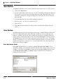
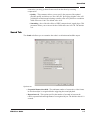
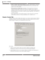
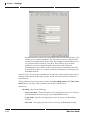
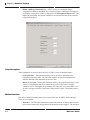
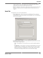
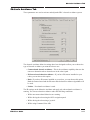
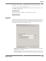
Chapter 8 Settings
• Must see another object before allowing a repeat - If this checkbox is selected,
the robot will not vocally identify an object more than once per encounter. This
option is set to off by default.
• Interrupt current sound to play a new one - This option allows the robot to
interrupt its audio output to play a new sound. For example, say your robot is
playing a CD and it sees the dog. It can stop to say "Dog" and then continue playing
the CD. If this box is not checked, sounds are played sequentially. This checkbox is
selected by default.
• Text to speech voice - This pull-down menu is used to select the voice that the
robot will use to read text. The system default voice is "default voice".
Remote Control Tab
This tab is used to enable, disable and customize your remote control parameters. Before
setting these options, you will need to configure your remote computer and your robot's
laptop computer so that they can communicate with each other.
Here's how:
1. Install a wireless network card in your remote computer according to the
manufacturer's directions. Do the same for your robot's laptop computer.
2. Install PCMCIA drivers on your remote computer according to the manufacturer's
directions. Do the same for your robot's laptop computer.
8-6
ER1 User Guide
Remote Control Tab
3. Install the drivers that came with your wireless card on your remote computer,
according to the manufacturer's directions. Do the same for your robot's laptop
computer.
4. Write down the laptop's name and wireless IP address.
5. Configure the remote computer's Windows operating system to connect directly to the
robot's laptop computer using a wireless connection. How you do this depends on
what version of the Windows operating system your computer is running. For
example, for Windows XP:
• Double-click on the wireless icon in the system tray (bottom right of your
Windows screen).
• In the Properties menu, select Wireless Net Tap.
• Add a new network.
• The SSID name for the new network should be: ADHOC.
• Go to Advanced Settings.
• Select Computer to Computer.
• Go to TCP/IP settings.
• Call up the TCP/IP Properties Menu and enter the following information:
• IP address of the robot's laptop (enter a value)
• Subnet Mask: 255.255.255.0
• Save the new network settings.
If you are unsure how to set up a wireless network on your version of Windows, check
the Windows Help files. If you are still having trouble, contact Evolution Robotics
Customer Support.
6. Next, configure the robot laptop's Windows operating system to connect directly to the
remote computer using a wireless connection. How you do this depends on what
version of the Windows operating system your laptop is running. For example, for
Windows 2000:
• Double-click on the wireless icon in the system tray.
• Select 802.11 Ad Hoc network.
• Enter the same SSID name you entered on the remote computer. In the above
example, this is ADHOC.
• Disable encryption.
• Open the Control Panel and select Network and Wireless Connections, then
Wireless Net Tap.
ER1 User Guide
8-7
Chapter 8 Settings
• Call up the TCP/IP Properties Menu and enter the following information:
• IP address of the robot's laptop: Enter a value. This must be different than
the IP address of the remote computer.
• Subnet Mask: 255.255.255.0
7. Save the new network settings.
8. Test the wireless connection between the two computers by using ping on either
machine. To do this:
• Open an MS-DOS window
• At the prompt, type: ping XXX.XXX.XX.X where instead of the X's, you should
enter the IP address of the OTHER computer. Here's an example of a failed
ping:
Microsoft Windows 2000 [Version 5.00.2195]
(C) Copyright 1985-2000 Microsoft Corp.
C:\>ping 192.168.12.1
Pinging 192.168.12.1 with 32 bytes of data:
Request
Request
Request
Request
timed
timed
timed
timed
out.
out.
out.
out.
Ping statistics for 192.168.12.1:
Packets: Sent = 4, Received = 0, Lost = 4 (100% loss),
Approximate round trip times in milli-seconds:
Minimum = 0ms, Maximum = 0ms, Average = 0ms
Here's an example of a successful ping:
C:\>ping 10.1.3.57
Pinging 10.1.3.57 with 32 bytes of data:
Reply
Reply
Reply
Reply
from
from
from
from
10.1.3.57:
10.1.3.57:
10.1.3.57:
10.1.3.57:
bytes=32
bytes=32
bytes=32
bytes=32
time=31ms
time<10ms
time<10ms
time<10ms
TTL=64
TTL=64
TTL=64
TTL=64
Ping statistics for 10.1.3.57:
Packets: Sent = 4, Received = 4, Lost = 0 (0% loss),
Approximate round trip times in milli-seconds:
Minimum = 0ms, Maximum = 31ms, Average = 7ms
C:\>
9. Click on the Settings button and then the Remote Control tab. Check the box for
Allow Remote Control.
10. Install the RCC software on your remote computer, and start the application.
11. Click on the Settings button again. In the Remote Control tab, check the box for
Control robot at this IP address. Enter the robot's laptop IP address in the space
provided.
8-8
ER1 User Guide
Email Tab
12. Leave the default as Port 9000.
Options are:
• Disable Remote Control - If this checkbox is selected, remote control of your
robot is disallowed.
• Allow remote control of this instance - If you want to remotely control your
robot, click this checkbox on the robot's laptop. You will also need to go to the
remote computer and click Control robot at this IP address. (If you close the
ER1 application, then restart it, you will have to re-select this option.)
• Control robot at this IP address - If this option is selected, the IP address, port
and password for the robot's laptop must be supplied.
• Allow API Control of this instance - If this option is selected, the ER1 can be
controlled using the API instead of through the RCC interface. If this option is
selected, a port must be specified. You may also specify a password if desired.
See the Application Programmer’s Interface section for details. Note that if this
option is specified, you cannot control the robot using the RCC software until
you discontinue your API session.
• Safety (Remote Control Timeout) - Use this option to override the safety
timeout setting. The default value is 1,500 milliseconds (1.5 seconds) between
the loss of remote connection and the robot stopping. Valid values are between
500 milliseconds and 10,000 milliseconds. Keep in mind that this value is the
amount of time that the robot will be in unguided motion. Increasing this value
may cause damage to people, pets or property.
• Reset the network connection now - If your computer and your robot are using
wireless communication, the present limitations of the technology mean that
connections can occasionally be dropped. The reset checkbox can be used to
reconnect the base unit to the remote instance, assuming, of course, that a
network connection is available.
Email Tab
This tab is used to set up ER1 email parameters for both incoming and outgoing email
(you must have Internet access on your laptop for this to work).
If you plan to program your robot to send and receive email, you need the following:
• A POP account for your robot.
• An email account for the robot.
ER1 User Guide
8-9
Chapter 8 Settings
• Evolution Robotics will provide a RobotMail email account that will allow your
robot to receive simple commands. You will need to provide a separate email
account for sending email from the robot. We strongly recommend that you set
up a separate email account for your robot. This will keep your personal
mailbox free of robot command emails, and will keep the robot from
downloading all your email to look for any that may be intended for the robot.
See the Message Receive Condition section for information on setting up your
RobotMail account.
Important Note: The messages transmitted to the robot are not direct instructions, but are
messages which, based on the sender, subject, and/or body will result in activation of a
scripted action.
These parameters must be correctly set before the If>Incoming email or the Then>Send
email features will work. These parameters do not have default values.
Options are:
• Incoming - Specify the following:
• Pop server name - This is the name of your incoming mail server. You will get
this information when you sign up for your RobotMail account.
• Login name - Specifies the login name you use to access your RobotMail
account.
• Password - The login password you use to access your RobotMail account.
8-10
ER1 User Guide
Motion Tab
• Check for mail every __ minutes - Specifies how often should the ER1
software should check with the server to see if it has an email. Five minutes is
the default.
• Leave messages on server - If this checkbox is selected, all incoming email
messages will be left on the server. This will allow you to download these
messages to your robot to another email address if you so choose.
• Outgoing - Specify the following:
• Smtp server name - This specifies your outgoing mail server. You can get this
information from your Internet Service Provider.
• Your name - This is the name you want to appear in your emails.
• From address - Specify your email address (complete address).
• Use a Reply-To address - If this checkbox is selected, you can specify a reply
to address that varies from the address from which the email was sent.
• Reply-To address - If Use a Reply-To address is enabled, specify the reply-to
address here (complete address).
Motion Tab
This tab is used to configure options related to the robot's motion. These options apply to
all movement related GUI activities.
The Rotation Angular Velocity options allow you to specify, in degrees/second, how fast
or slow the robot should rotate when performing various modes of action. The maximum
value is 90 degrees/second. The minimum value is 5 degrees/second.
• Manual control - The maximum speed of rotation when clicking one of the two
directional buttons.
The Motion Linear Velocity area allows you to specify, in centimeters/second, the
maximum linear velocity of the robot. The maximum value is 50 cm/sec, because the
robot cannot be operated safely above this speed. The minimum value is 5 cm/second.
• Manual control - The maximum linear velocity when clicking forward and reverse
directional buttons.
The Motor Power options let you specify the percentage of full power that the robot
should use under the following conditions:
• Stopped - When the robot is not moving, there is no reason for the robot's motor to
be powered. It causes the battery to drain faster, and makes noise. The default value
for this option is 0%.
• Moving - The robot does not need 100% power to perform most activities. It would
only need full power if it had to travel up a steep incline or if it were traveling over
a high friction surface, such as a shag rug. Leaving this value at the 60% default
value should provide adequate power for all other instances. Remember, the less
power you're using, the longer the robot's battery charge will last.
ER1 User Guide
8-11
Chapter 8 Settings
The Reverse sense of forward and backward arrows when manually moving the
robot checkbox will change the upward pointing arrow (under the Obstacle Avoidance
camera area on the RCC screen) from moving the robot forward to moving the robot
backward and vice versa for the downward pointing arrow.
The Restore Factory Settings button resets all motion values back to the original
defaults.
Obstacle Avoidance Tab
Obstacle
Detection
Area
8-12
ER1's obstacle avoidance feature uses a downward-pointing camera to detect obstacles in
front of the robot. The detection area is a trapezoid in front of the robot whose size and
shape depends on the height and angle of the avoidance camera. The avoidance algorithm
works by detecting the lines between regions with different colors in this trapezoid. Thus,
the avoidance algorithm works best on floors of uniform color without harsh edges (so
objects on the floor are easy to see).
ER1 User Guide
Obstacle Avoidance Tab
Positioning the Obstacle Avoidance Camera
The avoidance camera (the optional second camera) should be positioned at least two feet
off the ground. The camera should also be centered between the left and right wheels so
that it sees the same distance to either side of the robot. When using both cameras, it is
best that both cameras are centered, with the avoidance camera placed above the object
recognition camera such that the latter does not obscure the former. To properly angle the
avoidance camera, tilt it downward so that the bottom front edge of the robot is visible,
then tilt slightly up so that the bottom front edge is no longer in the camera's view. This
brings the detection area as close as possible to the robot, so that the camera can detect
obstacles right in front of the robot. The size of the detection area will depend on how high
the camera is and its angle. The higher the camera, the larger the detection area and the
sooner the robot will see obstacles. A larger detection area is better for general navigation,
but it might also interfere when approaching a target. For example, the robot is
approaching a painting on a wall. If it sees too far ahead, it might see the base of the wall
too soon and turn away before it gets close enough to the painting. Therefore, the ideal
height of the camera is dictated by the particular environment that the robot operates in
and the goals it has to accomplish. You should experiment with different camera heights to
see which would work best in your particular environment.
ER1 User Guide
8-13
Chapter 8 Settings
Avoidance Camera Calibration
Once the camera is placed on the robot, it needs to be calibrated for
best effect. To calibrate the camera, place two long straight edges
or put two parallel lines of tape on the ground alongside the robot.
These edges or tape lines should be right outside of the two wheels.
The avoidance camera should show a trapezoid formed from the
straight edges or tape lines.
The edges or tape lines should be such that they extend to or past
the top of the avoidance camera video feed as displayed on the
RCC.
Click on Capture New Calibration Image in the
Settings>Obstacle Avoidance tab. (Note that this must be
done on the robot’s laptop, not a remote computer.) The
obstacle avoidance camera’s current video display will be
captured and displayed on a submenu, with the trapezoidal
avoidance area outline overlaid on the image:
Avoidance Camera View
The avoidance camera view displays what the avoidance camera
sees pointing downward toward the floor, along with red marks
indicating where obstacles are detected. If there's just a straight
red line along the top of the image, no obstacle is detected.
When obstacles are seen, the red marks move down from the top
to indicate where the avoidance algorithm sees the obstacles in
the image.
Obstacle Avoidance At Work
Obstacle avoidance is always used in conjunction with moving toward a target. The target
is either some distance, some object that the robot has been trained to recognize, or some
color. If, in the course of going to a target, the robot sees an obstacle in the way, it will
attempt to go around the obstacle.
8-14
ER1 User Guide
Log Tab
Due to the limited field of view from the downward pointing camera, the robot can only
reliably go around small obstacles, like the legs and feet of a standing person. Large
obstacles may take the robot so far away from its original path that it won't be able to
reacquire the target. This is particularly true if the target is an object or a color that can
only be seen or recognized from certain angles. Also, complicated or constricted
environments may confuse the robot if it sees obstacles everywhere.
Log Tab
The Log tab is used to adjust the RCC logging function. The log file is a good place to
look if you have experienced an error or unusual behavior. The error messages should
point you toward the cause and help you avoid having the same problem in the future.
The log file is named er1.log and is located in the RCC program directory. The
following are the options available to alter the way errors are logged and viewed:
• Enable logging - If this checkbox is selected, errors will be logged in the log file.
When logging is enabled, every action taken by a running behavior or set of
behaviors is noted with a time and date stamp. The error messages are designed to
describe the problem causing the error. This should be the first place that you look
when you encounter a problem.
If you are using a wireless connection, the incoming remote connection to the
machine controlling the robot is monitored as well. This includes logging of
listening for connections, connection attempts (with the incoming IP address),
password and protocol matches and mismatches, logouts, and lost connections.
Please note that these will not be mirrored on the remote controlling system, since
some of them occur outside the scope of the connection and some would be
redundant because the remote system displays the information in various dialog
boxes during the connection process.
• Show log window on main screen - If this checkbox is selected, the log messages
will be shown at the bottom of the main screen
Important Note: Note that only the last 100 messages will be shown in this window. To
view the entire contents of the log file, click on the View Log button.
• View Log - To view the log file directly, click on this button. The log file will be
opened in Microsoft® Notepad. If you have a wireless connection to your robot, this
file contains log messages from your robot’s laptop (remote) and from the computer
that you are using to control the robot (local). These can be easily differentiated. In
the log file, the IP address of the remote computer, in parenthesis, will precede any
error messages it produces. Any error messages that do not have an IP address were
produced by the local computer. To see these messages, logging must be enabled in
both computers.
• Clear Log - To delete all of the entries in the log file, click on this button.
ER1 User Guide
8-15
Chapter 8 Settings
Joystick Tab
RCC allows joystick control of the robot, behaviors and/or the Gripper.
Options are:
• Enable Joystick Control: This checkbox, if selected, allows you to use a joystick
to control your robot, including controlling the Gripper open/close function. Note
that when the joystick is enabled (or at startup), if the current joystick position will
result in robot motion, the you will be asked if you want to enable joystick control.
Note also that some joysticks have more than just X,Y control. For example, the
Logitech WingMan® Cordless Rumblepad joystick has two independent joysticks
which control the X,Y and R,U axes. By adjusting the Axis menu settings, you can
make either the right or left joystick control the robot, or split the motion so that,
for example, the left joystick controls turning and the right one controls linear
motion.
Important Note: Manual motion using the joystick is allowed while behaviors are
running, as long a programmed motion is not currently in progress. If a programmed
motion is presently in progress, a message is logged telling the user why his manual
motion command is not being executed. Assuming that the user is still holding down the
joystick when the robot’s movement-related behavior finishes, the robot will then start
moving under the user’s manual control, and a message will be logged to that effect.
8-16
ER1 User Guide
Joystick Tab
• Joystick number - Use this pulldown menu to specify a joystick number. The
first joystick installed on your PC is considered Joystick 1 and the second is
Joystick 2, etc. You can only use one joystick at a time with the ER1.
• Axis: These parameters specify the kind of motion to be assigned to the
joystick(s) or the joystick buttons.
• Angular Axis - This is the left / right motion of the robot.
• Linear Axis - This is the forward / backward motion of the robot.
• With the joystick enabled, the user can reverse, if needed, the control axes
on the joystick map. To do this, just check the appropriate Reverse
checkbox.
• There is also a sensitivity setting, Sensitivity %, for the joystick that allows
the user to create a "dead zone" where joystick motion will not move the
robot. This can be useful for noisy joysticks or those that will not center
properly. The lower the sensitivity, the farther the joystick has to be moved
before the robot (and the red plus sign) will move. Once outside the dead
range, the remainder of the range is used for the full range of velocities.
Thus, if the sensitivity is set very low, the joystick will be more like an
on-off switch because the fill velocity range will be squeezed into a very
narrow range of joystick positions. Because of this sensitivity setting for the
joystick, the minimum velocity limits which were previously used to create
ER1 User Guide
8-17
Chapter 8 Settings
a dead zone were removed. This makes it possible to move the robot much
more slowly than was previously possible (less than 5 cm/sec, 5 deg/sec).
• Graphic Display: To illustrate what effect your axis settings will have on the
robot’s movements, the square graphics box on the right hand side of the menu
displays a red '+' which moves in response to your joystick commands to
simulate the resulting robot movement.
• Button Commands - Use these parameters to assign robot actions to the
joystick buttons.
• Button number - You can select the joystick button number in the pulldown
menu. You can also click in the textbox then press the joystick button and the
correct button number will be selected automatically. See your joystick
documentation for information on button number assignments. Choices of
actions to associate with buttons are:
• Do nothing - No button assignment.
• Close gripper - Closes the Gripper.
• Open gripper - Opens the Gripper.
• Run behaviors - This option is equivalent to clicking the Run it button for
the presently loaded behavior sequence. If this button on the joystick is
pressed, the robot will wait for the pre-programmed trigger condition, for
example, seeing a specific color. It will then will trigger the corresponding
actions.
• Stop behaviors - Equivalent to clicking the Stop button for the presently
running behavior sequence.
• Override IR bump sensor - By pushing the designated button on the joystick,
you can override the IR sensors’ obstacle detection. A good example of a use
for this would be driving the robot through a pile of balloons. Select a button
number and click the Override IR bump sensor to program that button to
override IR sensor bump detection.
• All of the above settings are stored on the computer to which the joystick is
attached, in that computer’s er1.ini file.
About Joystick Control
The ER1 RCC software allows you to control your robot and your Gripper by using a
USB compatible joystick. ER1 supports the following joystick operating configurations:
• Wireless remote joystick communicating directly with the robot’s laptop.
• Standard cable joystick plugged directly into the robot’s laptop.
• Wireless remote joystick communicating directly with the remote client, which is in
turn remotely controlling the robot’s laptop.
• Standard cable joystick plugged directly into the remote client, which is in turn
remotely controlling the robot’s laptop.
8-18
ER1 User Guide
Gripper Tab
Almost all USB joysticks are supported by the ER1 software, including:
• Logitech WingMan® Cordless Rumblepad
• Microsoft® Sidewinder® Joystick
• Belkin Nostromo N40 Gamepad
• Ken Eliminator Gamepad Pro
• Microsoft® Sidewinder® Game Pad PNP
Gripper Tab
The Gripper tab can be used to control the way the Gripper works while behaviors are
running, and when they are not running.
• Automatically grasp objects when not running behaviors - This checkbox, if
selected, specifies that the Gripper, when a behavior is not running, should close
when the IR beam is broken. This option is selected by default.
• Automatically grasp object when running behavior sets which do not use the
gripper - This checkbox, if selected, specifies that the Gripper should grasp any
objects that trigger the IR sensor when a behavior that does not use the Gripper is
running. This option is selected by default.
ER1 User Guide
8-19
Chapter 8 Settings
IR Sensors Tab
The IR Sensor Settings allow you to tell the robot where each sensor is located your robot.
It also allows you to monitor IR reflection strength, which indicates when obstacles are in
the robot’s path, and lets you set the flash rate of each sensor.
If you are using the sensors for automatic obstacle avoidance, you must position the
sensors in a triangle, with sensors 1 and 3 at either side of the robot, and sensor 2 in the
center of the robot.
You can also use this menu to determine which sensor is which. With the menu displayed,
point all three sensors up at the ceiling. The values should read at or around 0%. Then
point one of the sensors towards the floor. The sensor that changes value is the sensor you
moved. Do the same to identify the remaining sensors.
Settings are:
• Sensor number: Use each of the three pull-down menus to specify which sensor
number is located on the right, the left, and the middle of the robot. This is the
configuration for automatic obstacle avoidance. If you have your sensors set in
some other configuration, the robot doesn’t care where the IR sensors are located.
However, you can still use this menu to monitor the signal strength of the three
sensors. In that case, the labels 1, 2, and 3 simply refer to the sensor number, not the
sensor location.
• Stop Manual motion unless Ctrl key or a designated joystick button is held
down - Use these parameters to control robot motion.
• Use sensor # to stop _ forward or _ backward motion when reflection
reaches [%] - These parameters are used to stop forward or backward motion
when a specified reflection strength is reached. To set these parameters, select
the radio button for the desired IR sensor. Next select the forward or backward
radio button. Your selection should depend on whether a given sensor is
pointing forward or backward. To finish, select the desired reflection threshold
from the pulldown menu.
• Flashing LEDs - These parameters are used to adjust the reflection thresholds of
the various IR sensors. Note that each IR sensor can be set to a different value.
• Reflection Strength - The values under each of the sensor number pull-down
menus report the reflection strength of the IR signal presently being detected by
that sensor. This provides dynamic, real-time feedback, allowing users to view
sensor reflection values of various objects. (The robot determines whether or
not it is approaching an object by monitoring the reflection strength.) The
closer a sensor comes to an obstacle, the higher the reflection strength.
Threshold values for automatic obstacle avoidance are set in the Obstacle
Avoidance tab of the Behavior Settings menu. Threshold values for behavior
triggering and Stop on Sensor are set in the IR Sensors tab of the Behavior
Settings menu.
8-20
ER1 User Guide
IR Sensors Tab
• Use Center Sensor to stop manually controlled forward motion unless
CTRL key or a designated joystick button is held down - This allows the
center IR sensor to be used for bump detection when moving the robot
manually. See Stop Reflection Threshold below.
• Stop Reflection Threshold % - If Use Center Sensor is enabled, and the
center sensor's reflection is greater than or equal to the percentage value set in
Stop Reflection Threshold, the forward component of any motion initiated
with the arrow keys, joystick, or "virtual joystick" is stopped in order to avoid a
collision. This can be overridden by holding down the Ctrl key on the keyboard
or by pressing and holding a designated button on the joystick (see the Joystick
tab in the Settings menu).
Important Note: When overriding the IR bump detection, the virtual joystick on the screen
changes color to red as a warning. When the robot enters/exits the bump detection range
and forward motion is prevented, a log message appears.
• Flashing LEDs - This section is used to adjust the flash rate and the flash
thresholds of the ER1 IR sensors.
• Flash sensor <N> when reflection is greater than or equal to (%) - These
three checkboxes are followed by a scrollable textbox, where <N> is 1, 2 or 3. If
the checkbox is checked, the scrollable textbox is enabled. When checked, the
corresponding sensor's LED will flash if its reflection threshold is greater than
ER1 User Guide
8-21
Chapter 8 Settings
or equal to the value set. Changes take effect immediately, even in remote
control mode, but if the dialog box in cancelled, the old settings are restored.
This lets the user quickly experiment with different settings and flash rates. If a
box is not checked, the corresponding LED will remain off, unless one of the
other checkboxes is checked and its setting is active. Note that if a Move action
that uses the Stop on sensor feature is triggered, but the IR sensor threshold has
been exceeded, the robot will not move.
• Use IR Sensor obstacle avoidance reflection thresholds when appropriate If this box is checked, when a behavior which uses IR Sensor obstacle
avoidance is triggered and is moving the robot, the reflection strengths are set
to the values in the Behaviors Settings menu on the Obstacle Avoidance tab.
When the robot is done performing that behavior, the settings controlled by the
first three checkboxes are restored.
• Use stop reflection threshold when manually moving robot - This checkbox
is only enabled when the "Use the center sensor to stop manually controlled
forward motion..." checkbox above the Flashing LEDs group is checked. If it is
enabled and checked, when the user is manually driving the robot forward, the
center sensor's blink threshold is adjusted to the value set in "Stop reflection
threshold" and the other sensor's LEDs will be turned off. As soon as forward
motion is no longer called for, the blink thresholds and settings will return to
being controlled by the first three checkboxes.
• Flash Rate: There is a scrollable textbox for each of the three sensors. These
control the rate at which the sensor will blink when the thresholds described
above are exceeded. Note that the normal state of an LED is On. So, when the
IR reading is below the threshold, the LED will be on steadily, and when it is at
or above the threshold, it will start to flash at the given rate. The rates go from 1
to 16, with 1 being the slowest and 16 keeping the LED on continuously. The
rate of 16 causes the LED to stay on, but dim slightly when the threshold is
exceeded. This does not indicate any software or hardware malfunction, but is
intended behavior. The default rate is 10.
Important Note: If the sensors are unplugged and plugged back in, the flash rates and
thresholds specified in the Settings menu are properly restored.
IR Sensor Kit Specifications
The following are the specifications for the ER1 IR Sensor Kit.
• The IR sensor kit comes with 3 long range sensors capable of informing your robot
of obstacles.
• Each IR sensor employs an infrared (IR) LED and receiver to detect when an object
is in the path of the robot.
• Weight - 0.3 lbs
• Powered by your laptop through a USB connection.
8-22
ER1 User Guide
IR Sensors Tab
• Wide elliptical field of view enables detection of object within an area that at its
maximum is 30'' long and 20'' wide. Enables just three sensors to provide good
coverage of the forward half of the ER1.
• Special IR pulse technique makes sensor relatively immune to interference from
TVs, sunlight or other ambient light polluters.
• Sensors easily snap into your ER1’s XBeam channels, with no extra hardware
required or screws to tighten.
• Each sensor has a flexible neck to make positioning simple and precise.
• Attractive blue LED provides visible feedback, so you know when the ER1 has
detected an object.
• User adjustable object sensitivity through software.
• Output LED frequency adjustable through software.
• Can sense larger objects up to 30'' away.
• Objects as small as 2'' x 2'' can be detected from a distance of 15''.
Using The IR Sensors
The IR sensors allow your robot to avoid obstacles.
There are three sensors that can be used separately or in combination on the robot. They
are numbered 1, 2, and 3 in the RCC GUI. The sensors use infrared light, which is
invisible to the human eye. (Infrared light is commonly used as a signaling method in
remote controls for entertainment equipment, such as televisions and VCRs.)
The robot’s IR sensors each contain an IR emitter, an IR detector, and a blue LED. Each of
the robot’s IR sensors emit a pulse of infrared light. This light travels out along the field of
view and either hits an object or keeps on going. The blue LED blinks to indicate obstacle
detection.
If the light doesn’t hit an object, that light is never reflected
and therefore the robot assumes that there is not an obstacle in
front of the sensor.
2
If the light reflects off an object, some of the light returns to
the detector. The blue LED then flashes, to indicate to the
user that an object has been sensed.
The robot determines how close an object is by measuring the
strength of the reflection. The stronger the reflection, the
closer the object. However, larger or lighter colored objects
provide stronger reflections than smaller or darker colored
objects at the same distance.
1
3
ER1 User Guide
The ER1 software allows you to set threshold values (for each
IR sensor) above which obstacle avoidance behavior will be
triggered. By experimenting with these threshold values
while watching for the blinking of the blue LEDs that indicate
obstacle detection, users should get an intuitive feel for the
8-23
Chapter 8 Settings
best threshold settings for a particular environment. If the threshold is set to a high
number, a user would need to bring his hand very close before the sensor begins to blink.
If the threshold is set very low, the sensor will begin to blink even at a distance.
Push to Talk Tab
The Push to Talk tab lets you adjust compression and sound levels for transmitting your
voice from the remote client to the robot and for receiving ambient sounds from the
robot’s environment.
To use Push to Talk, first choose your settings. Unless a behavior is running, ambient
sound from the robot will continue to be transmitted from the robot to your remote client.
Settings for the local and remote computer can be configured from the local computer. To
select the local or remote computer, click on the desired tab to the right of the parameters.
• Enable listening and push to talk - Selecting this option allows you to use the
Push to Talk button.
For Talk, the settings are:
• Use this device - Allows you to choose the sound card to be used for talking.
• Use compression - Allows you specify automatic compression (checked) or lets
you set the compression level in samples per second (unchecked).
8-24
ER1 User Guide
Push to Talk Tab
• Samples per second - Lets you specify the sampling rate as one of the following
values: 8,000, 11,025, 22,050, or 44,100.
• Adjust levels (local computer) - Allows you to set the CD Player, Microphone and
Line In levels and balance.
• Adjust levels (remote computer) - Use this button to adjust the levels for Wave,
SW Synth, CD Player, Microphone, Line In, Phone, Line and PC Speaker. The Talk
values are on the left and the Listen values are on the right.
For Listen, settings are:
• Use this device - Allows you to choose the sound card to be used for talking.
• Adjust levels (local computer) - Allows you to set the Volume, Wave, SW synth,
CD Player, microphone and Line In levels and balance.
ER1 User Guide
8-25
Chapter 8 Settings
• Adjust Levels (remote computer) - Use this button to adjust the levels of Stereo
Mix, Mono Mix, CD Player, Microphone, Line In and Phone Line. Talk values are
on the left and Listen values are on the right.
Display Tab
The Display tab allows you to determine the order in which the behavior tabs are shown,
and the order of the behaviors in the Run menu in the Sequence section of the If column.
This is a local setting (similar to the Log tab settings), which affects only the system on
which it is adjusted. Once set, it applies to all subsequent behavior files which are used,
until you change it.
There are four sort orders:
1. Numeric - This is the default, which is the same as previous versions of ER1 RCC.
The behaviors are always sorted from 1 to 288, no matter what behavior name they
are given.
2. Alphabetic - If you change a behavior's name, it will appear in alphabetical order
with all other behaviors you have named, at the beginning of the behavior list. Any
behaviors which still have their default names will appear at the end of the list, sorted
numerically. This avoids the problem of alphabetically sorting the default names,
which would result in an order of Behavior 1, Behavior 10, Behavior 11, etc.
8-26
ER1 User Guide
Display Tab
3. Priority order, lowest to highest - Behaviors are displayed in order of their priority,
starting with the lowest priority behavior. Any of the behaviors that have the same
priority are sorted numerically, from lowest to highest.
4. Priority order, highest to lowest - Behaviors are displayed in order of their priority,
starting with the highest priority behavior. Any of the behaviors having the same
priority are sorted numerically, from highest to lowest.
ER1 User Guide
8-27
Chapter 8 Settings
About Tab
This tab displays the RCC software's version number, date and copyright information.
8-28
ER1 User Guide
Chapter 9
Behavior Settings
The Behavior Settings button lets you change settings for each specific behavior.
To set the Behavior Settings for an individual behavior, make sure that the behavior for
which the settings will apply is the active behavior and then click the Behavior Settings
button. A dialog box appears. Along the top of the box are a number of tabs, described in
the sections that follow.
Important Note: A good place to get ideas and help in creating behaviors is the ER1
community. If you have registered your ER1, you can join the ER1 community at
www.evolution.com.
Sight Tab
This tab is used to fine-tune aspects of the software’s object recognition capabilities,
which is used to recognize objects on which the software has already been trained.
Image Recognizer
This parameter is used to determine the specificity of object recognition.
ER1 User Guide
9-1
Chapter 9 Behavior Settings
• Match confidence threshold (%) – Allows you to set a minimum image
recognition confidence threshold. The software assigns a confidence percentage to
each object it recognizes, which is displayed in the Recognized Objects area. The
higher the percentage, the greater confidence the software has that it has correctly
recognized an object.
Color Recognizer
These parameters are used set the sensitivity of ER1’s color recognition feature.
• Color Tolerance - This parameter allows you to specify a minimum color
recognition tolerance value. The lower the number, the greater confidence the
software has that it has identified the correct color.
• Detect % of screen - Setting this parameter allows you to set the percentage of the
camera’s video display that must contain the specified color before a trigger
condition occurs. The higher the percentage, the larger the area a color must cover
in order to trigger an action. Valid values range from 0-100%. The default value is
20%.
Motion Detection
The motion detection settings allow you to specify the way that RCC detects motion.
There are two options:
• Tolerance - The Tolerance parameter indicates the amount of change there must be
between two consecutive images before the motion detection triggers. The accepted
9-2
ER1 User Guide
Sound Tab
values are from 0 to 256, with a default of 50. The higher the values, the more
changes must occur before the motion detection can occur.
• Detect % of Screen - This parameter adjusts the percentage of pixels on the screen
that have to change between two subsequent frames for motion detection to be
triggered.
Sound Tab
This tab allows you to set the sound parameters.
• Text to speech voice - Allows you to specify which Microsoft Text-to-Speech
preprogrammed voice the robot should use when speaking to you. Use the pulldown
menu to select an option.
• Speech Recognition Grammar - Use these parameters to specify how you would
like the robot to recognize speech.
• None - This parameter, if set, specifies not use a speech recognition grammar
file.
• Grammar file - Use this textbox to specify the path and filename of the speech
grammar file that you would like to use. You may also type in a list of words
that the robot will use as a grammar file. If you are using a wireless network,
note that the files displayed will be those saved on the robot’s laptop.
ER1 User Guide
9-3
Chapter 9 Behavior Settings
• Word Phrase list - Use this textbox to specify the words and phrases that you
would like the robot to recognize. Keep in mind that the robot will only
recognize the words that you have selected. Any words that do not match the
list will be ignored. Each word or phrase should appear on its own line. These
lines must be less than or equal to 1,023 characters. Only alphanumeric
characters, spaces and apostrophes are allowed. You can create the list inside
this textbox or by cutting and pasting the text out of a plain-text format
document. Remember that this grammar file will be used by all of the behaviors
in the behavior set.
Helpful Hints about Grammar Files
Here are some things to keep in mind if you decide to use or create a grammar file:
• The C:\\Program Files\ER1\sounds is the default directory where grammar
files are stored.
• When specifying a grammar file, the user can specify either the *.xml file or the
*.cfg file (the .cfg file is the compiled version of the .xml file). The only
difference is that the compiled version will run faster, but for most grammar files,
the difference will be trivial.
• If the user specifies a grammar file or a string of words, the speech recognizer will
not even try to recognize any other words.
• For information on grammar file syntax, see
http://www.w3.org/TR/speech-grammar/. For information on creating grammar
files, go to http://msdn.microsoft.com and search for the topic “creating grammar
files”.
Photo Tab
This tab is used to set up photo parameters.
Options are:
• Format – This parameter allows you to choose which format to use when saving a
picture from the robot’s webcam. The default value is .jpg. Choose one of the
following formats:
• .bmp
• .tif
• .png
• .jpg
• Quality - JPEG files use lossy compression, meaning that they do not exactly
recreate the original image. 100 means the least loss (best quality) and thus the
biggest file size, 0 means the most loss (lowest quality) and the smallest file
size.
• Smoothing - Compressing an image as a JPEG can cause sharp edges to appear
rough or jagged. Smoothing lets you specify how much to smooth rough edges
9-4
ER1 User Guide
Video Tab
created by the compression process. 0 means no smoothing, 100 means
maximum smoothing.
• Resolution - This box allows you to set the resolution of the photo. The higher
values mean higher resolution and larger file size, whereas the lower values specify
a lower resolution resulting in a smaller file size. You may also choose to accept the
default value set by the object recognition camera.
• Sequence Numbers – This area lets you chose whether or not to add a sequence
number to each photo, and if so, what is the next number to use. The sequence
number is appended to the name of the file, before the extension.
Video Tab
This tab is used to configure the video settings.
The options are:
• Record video - Select this option if you would like to record a video. This will
produce a .avi file. The file will be named video.avi and be saved into
C:\\Program Files\ER1 directory by default.
ER1 User Guide
9-5
Chapter 9 Behavior Settings
• Use camera - This specifies the camera that should be used to record the video.
If you only have one camera, that camera will be selected by default. If you
have two cameras, the object recognition camera will be used by default.
• Object - This parameter specifies to use the object recognition camera to
record video. See the Camera Tab section for information on designating a
camera for object recognition. This camera is used by default.
• Obstacle - Selecting this radio button specifies to use the obstacle
avoidance camera to record video. See the Camera Tab section for
information on designating a camera for obstacle avoidance.
• Specific - To designate a specific camera to record video, select this radio
button. The pulldown menu will be activated. Select the camera from the
pulldown menu.
• Frames per second - This pulldown menu is used to specify the frames per second
that the robot should use when capturing video. The available values are default, 1,
2, 5, 10, or 15 frames per second.
• Video Compression - These parameters are used to specify the type of compression
to use as well as the parameters associated with the compression type selected. Be
sure to consider your needs and the type of camera you are using when selecting
values.
• Type - This pulldown menu is used to select the type of video compression to
use. The default value is none.
9-6
ER1 User Guide
Video Tab
• Data rate - If the compression algorithm that you selected supports this
parameter, select the checkbox. The range of values depends on the compression
method chosen, the frame rate, the quality and the key frame rate. Pick a
reasonable value to correspond to your other settings, should you choose to set
this value manually.
• Quality - If the compression algorithm that you selected supports this
parameter, you can specify the percent of the optimal possible quality at which
to save the video file. Specifying a higher value will yield higher resolution, but
also larger file size. Selecting a smaller value will yield lower resolution, but a
smaller file size. The file size should be considered when emailing video files.
The default value is 85%.
• Key frame spacing - To select this parameter, select the checkbox and specify a
value. If you want to be able to scan quickly through your video, you will want
keyframes, which do not depend on previous frames for determining what is in
them. The first frame is always a key frame, since it can not depend on any other
frames. If you had no other key frames, and you wanted to start watching the
video from the middle, the system would have to decompress all the
intermediate frames to determine what was in the middle frame. If you have
keyframes, say every 10 frames, it would have to decode at most 10 frames to
determine what was in that section of video.
• Audio - Use these parameters to specify the audio settings to be used in conjunction
with video recording. See the Push to Talk Tab section for details on setting the
volume on a remote machine. Remember to set your sound card parameters to
optimize recording quality. The default is to record sound using a 11,025 sampling
rate, 8 bits per sample and channels set to mono.
• Record audio - If selected, this specifies to record audio whenever the robot
records video. If this parameter is selected and the Record video option is not
selected, a .wav file will be produced. If Record video and Record audio are
both selected, a .avi file will be produced. The file will be named audio.wav
and be saved into C:\\Program Files\ER1 directory by default. To change
the name of the file, use the Then name it option in the Record section of the
Then column.
• Use audio capture device - This specifies the audio capture device to use, for
example SoundMax® Digital Audio. Note that the RCC does not verify that
necessary recording devices are present and/or operational before running a
behavior that requires them. For example, a behavior that requires a microphone
to record sound will run whether or not a microphone is present. In this case, the
result will be a .avi file with no sound, and no error message will be displayed.
• First listed - If selected, this specifies to use the default audio capture
device. The default audio capture device will appear first in the pulldown
menu to the right of this parameter.
• Specific - Click on this radio button and select a specific audio capture
device to be used for recording.
• Samples per second - This parameter specifies the number of times per second
that the audio input should be sampled. Note that a higher sample rate will
ER1 User Guide
9-7
Chapter 9 Behavior Settings
produce better sound, but it will also produce a bigger file. Keep file size in
mind when emailing robot videos.
• Bits per sample - This specifies the number of bits to be used per sample.
Remember that the higher the number of bits, the better the sound. Also note
that a larger number of bits will produce a bigger file and use more disk space.
• Channels - Use these radio buttons to specify the number of channels to use
when recording. Most PC microphones are mono, whereas input from a stereo
microphone or a CD would require the stereo setting.
• Add a sequence number to each video - Use this parameter to append a number
on the end of a file name, before the file type extension. This parameter helps to
create unique filenames, thus reducing the probability of overwriting files by
accident. You may specify a number to start the sequence in the textbox below this
parameter. The default is 1. Note that this option is only applied when a filename is
specified in the Record section of the Then column. If a filename is not selected,
old files will be overwritten by new ones as they are created.
• Resolution - Use this parameter to select a resolution or create a new one. Be sure
that you specify a resolution that is produced by your camera.
Motion Tab
This tab is used to configure options related to the robot’s motion. Parameters can be set
for a specific behavior, otherwise the default values will be used.
Rotation Angular Velocity
The Rotation Angular Velocity options allow you to specify, in degrees/second, how fast
or slow the robot should rotate when performing various modes of action. The maximum
value is 90 degrees/second. The minimum value is 5 degrees/second.
• Fixed Distance – This parameter specifies the maximum speed of rotation when the
robot rotates an angular distance specified in degrees. The default value is 20.
• Rotate Toward Color - This sets the maximum speed of rotation when the robot
rotates towards a color. The default value is 10.
• Drive Toward Color – Use this parameter to set the maximum speed when the
robot drives toward a color. (It will need to turn to line up with the color if it is not
directly ahead. If the color happens to be moving, the robot will need to adjust its
course to follow it.) The default value is 20.
• Drive Toward Color (searching) - This parameter sets the maximum speed when
the robot is searching for a color. Note: Using a slower speed gives the robot more
time to identify the desired color. The default value is 10.
9-8
ER1 User Guide
Motion Tab
• Rotate Toward Object - This sets the maximum speed of rotation when the robot
rotates towards an object. The default value is 10.
• Drive Toward Object - Use this parameter to set the maximum speed of rotation
when the robot drives toward an object. It will need to turn to line up with the object
if it is not directly ahead. If the object happens to be moving, the robot will need to
adjust its course to follow it. The default value is 20.
• Drive Toward Object (searching) - This parameter sets the maximum speed when
the robot is searching for an object. Note: Using a slower speed gives the robot
more time to identify the desired color.
• Go to X, Y location - This parameter sets the maximum speed of rotation when the
robot is given a specific X, Y location.
Motion Linear Velocity
The Motion Linear Velocity area allows you to specify, in centimeters/second, the
maximum linear velocity for the different modes of motion. The maximum value of all
these settings is 50 cm/sec, because the robot cannot be operated safely above this speed.
The minimum value is 5 cm/second.
• Fixed Distance - This sets the maximum linear velocity to use when traveling a
fixed distance. The default value is 20.
• Toward Color - This parameter specifies the maximum linear velocity to use when
traveling towards a color. The default value is 20.
ER1 User Guide
9-9
Chapter 9 Behavior Settings
• Toward Object - If set, this parameter allows you to set the maximum linear
velocity to use when traveling towards an object. The default value is 20.
• Go to X, Y location - This parameter sets the maximum speed of the robot when
the robot is given a specific X, Y location.
Motor Power
The Motor Power options let you specify the percentage of full power that the robot
should use under the following conditions:
• Stopped – When the robot is not moving, there is no reason for the robot’s motor to
be powered. It causes the battery to drain faster, and makes noise. The default value
for this option is 0%. However, if the robot could stop on a sloped surface, then it
will need power to stay in place. In this case, the stop power should be set to greater
than zero.
• Moving –The robot does not need 100% power to perform most activities. It would
only need full power if it had to travel up a steep incline or if the robot is traveling
over a high friction surface, such as a shag rug. Leaving this value at the 60%
default should provide adequate power for all other instances. Remember, the less
power you’re using, the longer the robot’s battery charge will last. However, too
little power and the robot will not move reliably.
Collision Detection
The Enable collision detection checkbox lets you toggle collision detection capabilities
on and off. When collision detection is turned off, the ER1 will move without checking to
see if it has bumped into any objects. When collision detection is turned on, the ER1 will
use the camera's video feed to determine if the robot has collided with some object. In that
case, the ER1 responds by stopping and backing up a short distance before continuing on
its intended path. This option is set to off by default.
The Sensitivity field below the collision detection checkbox determines how tolerant the
ER1 will be to potential collision situations. The higher the sensitivity number, the more
readily the ER1 will detect collisions. (Conversely, the lower the number, the fewer
collisions it will detect.) You may need to tailor the sensitivity value to work best in the
environment that the ER1 is currently in. Keep in mind, however, that too high a
Sensitivity will result in false collisions being detected. On the other hand, too low a
Sensitivity will cause the ER1 not to detect actual collisions. (The default value is 50;
start with this and adjust accordingly for your environment.)
An important collision detection behavior occurs when all that the ER1 can sees is a
featureless object, such as a blank wall. In this case, the ER1 stops, because it is most
likely very close to the object, and therefore should stop moving towards it.
This behavior can be incorrectly diagnosed as a problem with the robot's motors, but if
you reorient the robot so that the camera's view is of a non-featureless environment, it
should continue its movement. If the robot still doesn't move, temporarily disable
collision detection, and restart the robot's behavior. The robot should move correctly. If it
does not, you should experiment with adjusting the robot's collision detection sensitivity
so that it will work correctly in your environment. (In rare instances of extremely
featureless environments, collision detection cannot be adjusted to work properly.)
9-10
ER1 User Guide
Obstacle Avoidance Tab
These parameters are used to activate and adjust the ER1’s obstacle avoidance system.
The obstacle avoidance behavior settings have been designed to allow you to choose the
type of obstacle avoidance you want the robot to use:
• Camera-based obstacle avoidance - This is the avoidance capability that uses the
camera to determine where obstacles are in the robot’s path.
• IR Sensor-based obstacle avoidance - If you have IR sensors installed on your
robot, you can choose this option.
• Both - If you have IR sensors installed on your robot, you can choose this option.
Both the camera-based and the IR sensor based obstacle avoidance algorithms will
be used.
• Neither - No obstacle avoidance is used.
The IR settings on the Obstacle Avoidance tab apply only when obstacle avoidance is
running. You can use obstacle avoidance under the following conditions:
• While movement-related behaviors are running.
• While driving the robot using the RCC navigation panel.
• While driving the robot using a joystick.
• While using Command Line APIs.
ER1 User Guide
9-11
Chapter 9 Behavior Settings
(Use the settings on the IR Sensor tab to set values that apply to IR sensor-based
triggering of behaviors.)
The sensor reflection strength percentage is the level at or above which the robot will
initiate avoidance of the obstacle sensed. That is, a high percentage will allow the robot to
come closer to a particular obstacle than a low percentage.
• Avoid obstacles using IR sensors - When this box is checked, the robot will use
the IR sensors to detect and avoid obstacles in its path. If desired, camera-driven
obstacle avoidance can be used in conjunction with IR sensor-based avoidance.
• Left sensor reflection strength (%) - When the robot’s left IR sensor senses a
reflection with a strength at or above this threshold, obstacle avoidance behavior
will be initiated.
• Center sensor reflection strength (%) - When the robot’s center IR sensor senses
a reflection with a strength at or above this threshold, obstacle avoidance behavior
will be initiated.
• Right sensor reflection strength (%) - When the robot’s right IR sensor senses
a reflection with a strength at or above this threshold, obstacle avoidance
behavior will be initiated.
• Disable during drive toward object or color - This parameter specifies that
the robot ignore obstacle avoidance when approaching an object or color using
Drive toward object or color. In other words, setting this parameter turns all
obstacle avoidance off. By default, the robot is disabled within 100 cm of an
object for Drive toward object and within 50% of the stop percentage for drive
toward color. Because the default stop percentage is 50%, 50% of 50% means
when the color is 25% of the screen. Why this is useful? When the robot is
within the "disable values" of the target, obstacle avoidance is disabled to allow
the robot to proceed to the target. This is useful if the robot is approaching a
painting on a wall or target near some obstacle.
• Within this distance of objects - This value specifies the number of
centimeters from the target that the robot should stop. This value should
never be set to less than 4cm, as there is a good chance that the robot will
collide with the intended target.
• When color is this fraction of the stop percentage - This parameter
specifies that the robot should stop when the selected color takes up a
certain percentage of the screen.
When you have finished adjusting the parameters, click the Ok button. You may cancel at
any time by clicking on the Cancel button.
The Restore Factory Settings button resets all motion values back to the original
defaults.
Run Tab
The Run Tab allows you to specify how many times a behavior should run, and/or how
long it should wait before running once again.
9-12
ER1 User Guide
Run Tab
• Let behavior run more than once - Select this checkbox to allow a behavior to run
again and again. This value is set to off by default.
• Prevent from restarting for (seconds) - This parameter specifies the time
interval in between rerunning the same behavior. Remember that the behavior
must be triggered by something specified in the If column before it can occur.
• Priority - Use this option to assign a priority to a behavior. Use the up and down
arrows to change the priority. Values between 1 (lowest) and 288 (highest) are
accepted. The default value is the number of the behavior, i.e. Behavior 1 has a
priority of 1, Behavior 2 has a priority of 2, etc.
• Allow conflicting higher priorities to terminate this behavior - Clicking on
this checkbox allows the current behavior to be terminated by a conflicting
behavior of a higher priority. A conflict occurs when both behaviors use the
same functionality (for example, the robot playing a sound, sending an email,
running a program, recording) at the same time or both behaviors try to make
use of the same camera. Note that if they both make use of the same
functionality, but one has finished, say, playing a sound, and is now just driving
the robot, then the behaviors will not conflict.
• Allow nonconflicting behaviors to run at the same time as this behavior Selecting this checkbox allows nonconflicting behaviors to run in parallel to
this behavior.
• Pause for # units after running - Use this parameter to specify a time that the
robot should pause in between performing this behavior and running the next
ER1 User Guide
9-13
Chapter 9 Behavior Settings
behavior. Enter the number in the textbox and select a unit from the pulldown
menu. Available units are second(s), minute(s), hour(s) and day(s). Pauses
always occur after all other actions in the behavior have completed, including
actions which load another behavior file. You can use a behavior which pauses,
but does nothing else to simulate a delay at the beginning of a behavior. For
example, if you want a behavior which performs a task 10 seconds after seeing
an object, use one behavior which has as its If condition seeing the object, and
as its only action has a pause set to 10 seconds in the Behavior Settings menu’s
Run tab. Make a second behavior which sequences after the first, and performs
the task. It will be triggered 10 seconds after the first behavior is triggered.
Helpful Hints
• If two behaviors are set to the same priority, and they conflict, the one with the
higher behavior number will be treated as the higher priority behavior.
• Behaviors are not triggered in parallel. For example, if the robot's camera views a
scene containing two separate objects it recognizes, one of which would trigger
behavior A and the other of which would trigger behavior B, it has to see that scene
twice to trigger both behaviors (assuming that they were properly set to run in
parallel). Also, when any behavior is triggered, it resets the accumulated triggers of
every other behavior.
• Running behaviors from different files at the same time is not supported.
• If one behavior is set to load another behavior set, once that behavior is triggered no
more parallel behaviors will be allowed to start until the load of the new file takes
place (and that occurs after the other aspects of the behavior, such as moving the
robot, have finished). Once the new file is loaded, parallel behaviors within it can
run.
• If a behavior set file is loaded with the option of unloading it after a certain
behavior has run, any parallel behaviors running when it has completed will be
terminated so that the file can be unloaded right away.
• Note that some behaviors may conflict with each other because they make use of
the same camera. For example, if one behavior shoots a video with the obstacle
avoidance camera and the other moves the robot and uses obstacle avoidance, that
will be considered a conflict, and handled according to the rules described
previously.
Examples
Conflict Example
1. Behavior 1 (Priority 1) is configured to drive the robot 10 feet forward when it sees
object A, and has the Allow conflicting higher priority box checked.
2. Behavior 2 (Priority 2) is configured to drive the robot 5 feet backward when it sees
object B.
3. The user clicks Run to start the behaviors.
9-14
ER1 User Guide
Joystick Tab
4. The robot sees object A.
5. It starts to drive forward.
6. Then it sees object B.
7. Behavior 2 would then stop Behavior 1 because it is higher priority and conflicts and
Behavior 1 had this box checked on its run tab.
Non-Conflict Example
1. Behavior 1 (priority 1) is set to drive the robot 10 feet forward when it sees object A,
and has this box checked.
2. Behavior 2 (priority 2) is set to say "Hello" when it sees object B.
3. You start behaviors and the robot sees object A.
4. It starts to drive forward. Then it sees object B and, while it continues to move
forward, it will say "Hello".
Joystick Tab
You can assign a specific behavior to be triggered by a joystick button press. This feature
is accessed by in the Joystick tab of the Behavior Settings menu. This means that the
button press itself is the trigger condition, causing the immediate triggering of the
programmed corresponding actions. (As differentiated from the Settings menu>Joystick
tab>Button commands>Run behaviors choice, which simply tells the ER1 to start
monitoring for a programmed trigger condition.)
To use this function, select the Trigger active behavior on joystick button press
checkbox. You may select a button to trigger a behavior by using the pulldown menu. Or,
as for the Settings menu, you can click in the textbox, then press the desired joystick
button. That button number will be displayed in the pulldown menu.
ER1 User Guide
9-15
Chapter 9 Behavior Settings
Important Note: The same joystick button can be used to start behaviors (configured in
the Joystick tab of the Settings menu) and to trigger a behavior (configured in the
Joystick tab of the Behavior Settings menu). If you set it up this way, you can, for
example:
1. Open a new behavior set.
2. Click the Behavior Settings button to display the Behavior Settings menu, then click
on the Joystick tab.
3. On your joystick, press button 1. This tells the ER1 to trigger Behavior 1 immediately
when button 1 is pressed. (Remember, the behavior still has to be in the Run it state
for the trigger to be recognized. If you pressed the button at this point, nothing would
happen, because no behavior was waiting for the trigger condition.) Click Ok.
4. Click on the Settings button to display the Settings tab, then click on the Joystick
tab.
5. Click on Enable joystick control. (The active behavior is the behavior that is
presently displayed in the GUI. For a new behavior set, this is Behavior 1.)
6. In Behavior 1, go to the Then column. Select the Play a Sound checkbox. Type in
“Hello, I’m the ER1” in the Speak a phrase textbox.
7. Use the joystick as usual to command the robot to move.
8. When you would like the robot to speak your phrase, press Button 1.
9. This will trigger the active behavior, causing the robot to speak the phrase you
typed in.
9-16
ER1 User Guide
IR Sensors Tab
10. If you’ve got your Behavior Settings configured so that the behavior runs only once,
the behavior will consider itself complete, performing the equivalent of clicking the
Stop button on the GUI.
11. You can continue to use the joystick to drive the robot. Just press Button 1 again when
you want it to speak the phrase you programmed.
Important Note: While the behavior is running, the joystick will not move the robot. This
behavior is analogous to the arrow keys or the movement buttons on the GUI.
Remember, the joystick commands are passed over remote control, so you can drive a
robot using a joystick connected to your remote control system (without the need for a
wireless joystick).
IR Sensors Tab
The IR settings on the IR Sensor tab apply only when a behavior is triggered by an IR
sensor and when the Move section of the Then column is programmed to cause the robot
to stop its programmed movement if an obstacle is detected.
(Use the parameters on the Obstacle Avoidance tab to set values that apply to
automatic obstacle avoidance.)
ER1 User Guide
9-17
Chapter 9 Behavior Settings
Logic Tab
The Logic tab allows you to AND or OR any triggers you specify in the If column.
• OR all of checked IF conditions - If this option is selected, only one of any
number of selected trigger conditions must be met. This is the default condition.
• AND all of checked IF conditions - If this radio button is selected all of the trigger
actions must be met before a behavior will be initiated.
For example, you've got the Logic set to AND for Behavior 4, with three separate triggers
necessary. You've got the Logic set to OR for Behavior 5, with only one trigger necessary.
Two of the three necessary triggers occur for Behavior 4, but nothing happens because it
is still waiting for the 3rd trigger. Before that happens, Behavior 5's trigger condition
occurs. So, Behavior 5's Then actions run. And all of Behavior 4's triggers are "reset" to
0. That is, they're starting over again from scratch, and all three must occur again before
Behavior 4 will trigger.
Note that even if the Logic is set to AND, and you choose three objects for Sight to
trigger on, it only takes recognition of one of the objects to satisfy the Sight trigger
condition.
The log entries will keep track of the multiple trigger conditions, for example:
(10.1.3.108)
(10.1.3.108)
(10.1.3.108)
(10.1.3.108)
(10.1.3.108)
(10.1.3.108)
9-18
01/10/03
01/10/03
01/10/03
01/10/03
01/10/03
01/10/03
15:42:41.923
15:42:41.933
15:42:49.755
15:42:49.765
15:42:54.371
15:42:54.371
Saw object one dollar, matching Behavior 1
Behavior 1: 1 out of 3 'IF' conditions have been met
Object entered gripper, matching behavior Behavior 1
Behavior 1: 2 out of 3 'IF' conditions have been met
Sound level 7, matches Behavior 1
Behavior 1: 3 out of 3 'IF' conditions have been met
ER1 User Guide
Load Tab
(10.1.3.108) 01/10/03 15:42:54.381 Triggering Behavior 1; it will not be allowed to be
re-triggered
(10.1.3.108) 01/10/03 15:42:54.391 Speaking phrase 'saw money and gripper was triggered'
(10.1.3.108) 01/10/03 15:42:54.411 Closing gripper
Note that the If column heading changes according to the way the Logic tab is set. If it is
set to AND, it looks like this:
and if the Logic tab is set to OR, the column heading looks like this:
Load Tab
This tab allows you load another behavior file and trigger behaviors in that file. Note that
this action is performed after all other actions in a behavior set. Note that when you are
using a wireless network to control your robot, this tab will be disabled as it provides a
view of behaviors on the local, not the robot’s, system.
• Run behaviors contained in another file - Click on this checkbox to allow other
behavior set files to be used.
• Behavior file name - Specify the path and filename of the behavior file to be used.
This sort of behavior file reference can be nested up to 10 files deep. Each file may
ER1 User Guide
9-19
Chapter 9 Behavior Settings
use its own speech recognition grammar. Remember that if you are controlling the
robot remotely, the behavior file must be located on the remote machine.
• After loading, trigger behavior (name or number) - Use this option to specify
the behavior name or number to be run. If this option is not set, the behavior file is
loaded and RCC waits for one of its trigger conditions to be met.
• Return after behavior (name or number) __ is done - This option specifies when
RCC should return to the original behavior set. This also unloads the specified
behavior set. If this option is not specified, then the loaded behavior file will not be
unloaded until all of its behaviors complete, or the Stop button is pressed.
Important Note: When a file is loaded on top of another, any timed behaviors in the
previous file are skipped (and rescheduled, if appropriate) until the previous file becomes
the currently active behavior set. Also note that if the loaded behavior set uses the Record
action and writes out a file with a sequence number, the modified behavior file is not
written back out to the disk when it is unloaded. Another thing to keep in mind is
recursively calling the same behavior file which you are modifying, either directly or
indirectly through an intermediate behavior file. Loading will always use the on-disk
version of the file, so when the file is loaded, it will be the unmodified version which is
loaded, which might behave differently from the in-memory version.
Apply This Page to All Behaviors Now
There is a useful feature in the Behavior Settings: the Apply This Page To All Behaviors
Now button on the bottom on the Behavior Settings dialog box. If you click on the
button, the current property page's settings are immediately applied to all 288 behaviors.
Note that clicking the Cancel button does not undo the change.
9-20
ER1 User Guide
Chapter 10
ER1 Command Line
Interface
Evolution Robotics’ ER1 Robot Control Center software provides GUI functionality for
controlling your robot. We also provide the Command Line Interface described in this
chapter so that you can control your robot directly, instead of using the GUI. With this
Interface, and some programming knowledge, you can:
• Access the digital inputs and outputs and analog inputs of the robot, for use with
custom sensors, or for controlling custom devices. This allows you to add your own
accessories such as sonar sensors.
• Generate a sequence of motions algorithmically. For example, you could program
the robot to travel around the perimeter of a circle, or to “dance”, without entering
each component of the motion as a separate behavior.
• Use the ER1’s vision system to control external devices. For example, you could
write a program which integrates the robot with your home automation system and
have it turn on your home theater system and dim the lights when you show it a
particular DVD box.
ER1 User Guide
10-1
Chapter 10 ER1 Command Line Interface
Because the API is written in a language neutral way, they can be used by most
programming and scripting languages including C, C++, Perl, Java, Visual Basic, etc. The
API also works equally well when issued from the laptop controlling the robot and from
another machine via a wireless network.
Accessing the API
The API is accessed by opening a TCP/IP socket to er1.exe and sending text commands
along the socket.
Activating the feature is done via the Remote Control tab of the Settings dialog box.
There is a new remote control option, labeled Allow API control of this instance. To
activate:
1. On the robot’s laptop, with ER1 running, choose the Settings button, select the Sight
tab and click on the Allow API Control of this instance checkbox.
2. On the remote client running ER1, click on the Settings button, and then the Remote
Control tab and click on the Disable Remote Control checkbox.
This makes it such that you cannot control a robot with both remote control and the API at
the same time.
10-2
ER1 User Guide
Telnet Windows XP Setup
Also, once the API connection is established and the user has "logged in" (see below), a
modal dialog box pops up on the robot's system. This prevents any GUI interaction with
the robot until the API connection is closed, or the button in the dialog box which allows
the connection to be terminated is pressed.
There is also a checkbox in the dialog which allows the user to turn off the API interface
without having to bring up the Settings menu. This prevents a malicious user, or a
wayward program, from continually reconnecting to the robot and locking out the user.
Telnet Windows XP Setup
This interface allows the telnet program to be used to connect to the robot and try out the
commands.
Telnet programs vary, but here's a description of how you would connect to the robot using
the one which comes with Windows XP:
1. Start the ER1 RCC software, click on the Settings button, select the Remote Control
tab, and click on the robot’s laptop Allow API control in this instance. (You can use
the same port and password which you would normally use for remote control. The
password can also be empty.)
2. On the remote client PC, click the Start button on the taskbar. Click Run, and type the
following in the Open field:
telnet <ip address> <port>
e.g.:
telnet localhost 9000
or
telnet 10.0.0.2 9000
substituting the IP address of the system running er1.exe (localhost if it is the same
machine that you are going to run telnet on), and the port number being used in the
Remote Control tab.
3. Since local echo is off, by default, you will not be able to see what you type as you
type it. To correct this, type:
Ctrl+]
4. This will take you to command mode for telnet. Type:
set LOCAL_ECHO
5. Then, hit the enter key twice. The first time turns on local echo mode, and the second
takes you back to your telnet session to the robot, blanking the screen.
Older Windows Telnet Setup
For older Windows telnet programs, e.g. Win98 and NT4:
1. Follow steps 1 and 2 above.
ER1 User Guide
10-3
Chapter 10 ER1 Command Line Interface
2. To turn on local echo, use the Terminal / Preferences... menu item in telnet, click the
Local Echo box, then click OK.
Using the Telnet Connection
Now you can type commands to the ER1 API and see what you are typing.
1. Make sure you are connected by hitting the Enter key once. You should see the word:
OK
appear on the next line.
2. You can now type just about anything and it will show you a list of valid commands.
If you have set a password using the Remote Control tab, the only valid command
initially is login. Type:
login <password>
where <password> is the correct password (case sensitive) followed by the Enter key.
3. If you see OK, you are logged in and can begin issuing commands to the robot from the
remote client.
4. Also, at this point, you will see a dialog box on the robot pop up, preventing any
interaction with the robot's GUI until the API connection is closed, either by you or by
telnet.
5. Test out your setup by typing the following, then pressing ENTER:
play phrase "hello"
The robot should speak the word hello.
6. If you type an incorrect or incomplete command, you will be prompted with a list of
correct commands. For example:
?
Error: '?(*)', Expected 'clear', 'events', 'input', 'move', 'output',
'play', 'sense', 'set', or 'stop'.
set
Error: 'set(*)', Expected 'voice', 'linear velocity' (or 'v'),
'angular velocity' (or 'w'), 'power stopped', 'power moving', 'collision detection', 'obstacle
avoidance', 'confidence threshold', 'color tolerance', or 'color percentage'.
move
Error: 'move(*)', Expected 'rotate toward', 'drive toward', 'x', 'y', or a distance.
7. To quit telnet, either click on the close button at the top right, or (XP version) press:
Press Ctrl+] and then type quit.
Press Enter.
10-4
ER1 User Guide
Commands
Commands
Here's a description of the commands that are currently implemented. In general,
commands and their parameters are not case sensitive, though object names are case
sensitive.
Commands to the robot are always of the form:
<command><Enter>
Every command is acknowledged with either an:
OK<Enter>
or, if something goes wrong:
Error: <error message><Enter>
Examples
Here are some examples of API commands:
move 6 i
play phrase "I am moving 6 inches forward"
move -20 c
play phrase "I am moving 20 centimeters backwards"
move 90 d
play phrase "I am moving 90 degrees to the left"
move -180 d
play phrase "I am moving 180 degrees to the right"
play phrase "I will now detect sound levels"
sense sound level on
events
set voice "Microsoft Mary"
play phrase "I am Microsoft Mary"
set voice "Microsoft Mike"
play phrase "I am Microsoft Mike"
set voice "Microsoft Sam"
play phrase "I am Microsoft Sam"
set v 10
move 2 f
play phrase "I am moving at 10 centimeters per second"
set v 50
move 3 f
play phrase "I am moving at 50 centimeters per second"
set w 10
move 270 d
play phrase "I am turning at 10 degrees per second"
set w 50
move -270 d
play phrase "I am turning at 50 degrees per second"
Command Quick Reference
Here’s a list of the commands. See later in the chapter for descriptions, examples, etc.:
er1
exit
gripper
gripper
gripper
gripper
ER1 User Guide
auto
close
open
status
10-5
Chapter 10 ER1 Command Line Interface
gripper stop
IR
move
move rotate toward object
move rotate toward color
move drive toward object
move drive toward color
play file
play phrase
stop
sense
sense gripper
clear
events
sense IR
set IR
set voice
set linear velocity
set angular velocity
set power stopped
set power moving
set collision detection off
set collision detection on
set obstacle avoidance off
set obstacle avoidance on
set confidence threshold
set color tolerance
set color percentage
input digital
output digital
input analog
Clear Command
Clear
Usage:
clear
The clear command throws away all events which have not yet been sent to the user.
ER1 Command
ER1
The ER1 command can load and run a specific behavior.
Usage
er1 <behaviorset_filename> -r <behavior name/number>
-q <behavior name/number>
Parameters
behaviorset_
filename
-r
10-6
Specifies the behavior set file to load. Note that filenames with spaces in them must
appear in double quotes.
Runs and triggers the behavior set specified.
ER1 User Guide
Events Command
behavior
name/number
Specifies a behavior number or behavior name within the behavior set. If a behavior is
specified, only this behavior, not the entire behavior set, will be run. Remember this
behavior must be triggered in order to run.
-q
This parameter specifies that after all of the behaviors complete, the program exits. If a
behavior is specified after -q, the program will exit after that behavior completes. This
parameter cannot be specified unless -r is set.
behavior
name/number
Specifies a second behavior within the behavior set. This behavior will be run after the
previous behavior specified. Remember this behavior must be triggered in order to run.
After this behavior runs, the specified behavior set quits.
Events Command
Events
Usage:
events
The events command allows the robot to send back information from its sensors (if
enabled) as well as sound and move completion notices.
The command is acknowledged with an OK message, then events are sent as they happen.
Events are terminated by the receipt of any command, even a blank line. It is
recommended that a blank line be used to terminate the sending of events because
otherwise a programmer may confuse an event message for a status return from a
command being issued.
In other words, the user should:
1. Issue the events command.
2. Look for the OK.
3. Parse the event messages as they come down.
4. Then, when ready to act on one of the events, send a blank line and wait for the OK
from that.
5. Event messages will be turned off, though they may still accumulate.
The issuing of new move and play commands clear any pending completion messages
from the corresponding command. That makes it easy to see that a message is from the
most recently issued command. Also, only the most recent sound level event is kept.
Here are examples of event messages.
speech hello
sound level 8
sound level 24
object spot new (23%) (117,16,19.876 Inches)
move done
play done
play error Sound file C:\sound.txt not found or don't know how to
play it
move error Cannot connect to the robot hardware.
ER1 User Guide
10-7
Chapter 10 ER1 Command Line Interface
Here is what happens when the robot recognizes an object:
object <“name”> <features matched> \
<total features> <x> <y> <distance in cm>
The object name is always surrounded by double quotes. The distance is always in
centimeters and has one decimal place.
Exit Command
Exit
Usage
exit
Description
This command causes er1.exe to exit. This will typically be confirmed with an OK, but
this is not guaranteed. The socket over which the connection to the API is made will be
closed when ER1 exits.
Gripper Commands
The Gripper can be commanded to open and close and report status through the supplied
Command Line API command:
gripper <action>
Where <action> is one of:
auto
close
open
status
stop
The API also allows you to read the state of the Gripper using the sense gripper
command.
All of these commands are described in detail in the sections that follow.
Gripper Auto
Usage
gripper auto
Description
This command sets the Gripper so that it will close when the IR beam from the IR LED is
broken.
Parameters
None.
10-8
ER1 User Guide
Gripper Commands
Returned Values
None.
Gripper Close
Usage
gripper close
Description
This command closes the Gripper.
Parameters
None.
Returned Values
None.
Gripper Open
Usage
gripper open
Description
This command opens the Gripper.
Parameters
None.
Returned Values
None.
Gripper Status
Usage
gripper status
Description
This command returns the status of the Gripper.
Parameters
None.
Returned Values
The message returned is in the format:
OK {postion} {object status} {auto status}
ER1 User Guide
10-9
Chapter 10 ER1 Command Line Interface
where position is one of:
open
closed
opening
closing
unknown (not fully open or closed)
and object status is one of
empty
full
unknown (IR LED beam is off)
and auto status is one of
auto
manual
Gripper Stop
Usage
gripper stop
Description
This command stops the Gripper from moving. It will also take the Gripper out of auto
mode. (See Gripper Auto for details.)
Parameters
None.
Returned Values
None.
Sense Gripper
Usage
sense gripper
Description
This command checks to see what the Gripper is doing at that moment.
Parameters
None.
Returned Values
• gripper opened - Gripper finished opening.
• gripper closed - Gripper finished closing.
• gripper filled - Object has entered the Gripper.
• gripper emptied - Gripper opened via the Open button on the motor enclosure.
10-10
ER1 User Guide
IR Commands
IR Commands
These commands control the IR sensors.
Set IR
Usage
set ir obstacle avoidance <state>
{all <refl> | {left <refl> center <refl> right <refl>}
{disable distance <distance>}
{disable percentage <percentage>}
Description
This command turns obstacle avoidance using the IR sensors on or off, and sets the
reflection thresholds for the three sensors as well as the disable distance and percentage.
Parameters
state
all
left center
right
ref1
distance
percentage
disable
distance and
disable
percentage
On
or off
Specifies all three sensors (not to be used in combination with left, center, and right).
The three locations, left, center and right can appear in any order and any combination,
and should not appear if <state> is being set to off or if all is specified.
This parameter is the reflection strength, from 1 to 100. The value 50 is the default.
This is the distance, in centimeters, at which the robot stops from an IR-detected object.
When color is this fraction of the stop percentage, motion is stopped when the robot is
moving toward a color.
These values apply to both camera-based obstacle avoidance and IR Sensor obstacle
avoidance. Setting these values for either type of obstacle avoidance sets their value for
the other type of obstacle avoidance.
Important Note: The argument obstacle avoidance can be abbreviated to be oa. For
example:
set ir oa on all 50
IR
Usage
ir {all | {{sensor} <sensor number>}}
{threshold <refl> flash <rate>}
Description
This command lets you read the current values from one or more IR sensors, or set the IR
sensors to send an event and/or flash when a given threshold is reached.
Parameters
all
ER1 User Guide
Means all three sensors. Not to be used with {sensor <sensor number>}.
10-11
Chapter 10 ER1 Command Line Interface
sensor number
Indicates which sensor (1, 2, or 3). Not to be used with all. If threshold is added, it must
be followed by a <refl> value.
refl
This is the level at or above which the IR sensor will flash its LED and fire an event.
Values range from 1 to 100, with 50 as the default.
rate
The rate is a number from 0 to 16. This is the rate at which the LED will blink when
<refl> is reached. 0 (which is the default) means that the LED should stay off. This
parameter can only be set to 0 by using the API. The lowest value allowed by the GUI is
1. One is the slowest blink rate, and 15 is the fastest. Sixteen makes the LED stay on.
Using 0 and 16 the user can directly control the LED to keep it on or off all the time.
threshold and
flash
The threshold and flash arguments can appear in any order and combination. For
example:
ir all flash 5
ir all threshold 90 flash 5
ir sensor 3 flash 10
The word sensor after the command ir is optional. If the line ends after
<sensor number> (or all), the current readings from that sensor (or all sensors) is
returned after the OK. The format of the returned values for each sensor is:
<current reflection value> <threshold> <flash rate>
For example:
ir
OK
ir
OK
all
68 50 0 77 50 0 75 50 0
1
68 50 0
Important Note: The IR obstacle avoidance values, manual motion stop values, and
Settings menu IR Sensors values for LED flash rates are ignored while under API control.
Sense IR
Usage
sense ir
Description
This command allows events in which the IR reflection has reached the threshold to be
seen by the events command.
Parameters
None.
Returned Values
The format of IR sensor events is:
ir <sensor number> <reflection reading>
where <sensor number> indicates which sensor (1, 2, or 3), and reflection reading is the
reflection strength read from that IR Sensor.
10-12
ER1 User Guide
Move Commands
The events do not accumulate -- only the most recent reading is sent. That means, if
between the time you issue the sense ir and events commands is long, you will not see
many IR events, just the last one which reached the threshold.
Move Commands
The move command makes the robot move.
The API responds to the command after it has been verified, but before the robot has
completed the motion. If another move command is issued before the robot completes the
previous one, the prior move command is interrupted. See the events command for how
to determine when the move command is complete.
Move Distance
Format:
move <distance> <units>
Parameters:
<distance>
<units>
This is a positive or negative floating point number.
This parameter is inches, centimeters, meters, feet, or degrees.
Since the first letter of each of these units is unique, anything which begins with that first
letter is assumed to be the correct word. This allows abbreviations, such as in:
move 30.5 i
move -2 ft
Examples:
move 90 degrees
move 50 feet
move -5.3 cm
Move Rotate Toward Object
Format:
move rotate toward object <object name>
Parameter:
<object name>
This is the name of an object in the library. It is case-sensitive. If it contains spaces, it
must be surrounded by single or double quotes.
Example:
move rotate toward "Spot Page 1"
Move Rotate Toward Color
Format:
move rotate toward color <r> <g> <b>
ER1 User Guide
10-13
Chapter 10 ER1 Command Line Interface
Parameters:
<r>
This parameter is the red color value (0 to 255).
<g>
This is the green color value (0 to 255).
<b>
This sets the blue color value (0 to 255).
Example:
move rotate toward color 255 0 0
which rotates the robot towards the color red.
Important Note: Are you not sure how to determine the RGB values of an object? Try
downloading and installing GIMP (Gnu Image Manipulation Program) from
www.gimp.org. It is a free program. Using the ER1 camera, take a snapshot of the object
in question. Open the file in GIMP. Use the dropper tool to select the color you want to
analyze. The RGB values will be displayed.
You can also use Microsoft® Paint to analyze the colors. Again, capture the image using
the ER1. Open the file in Paint. Select the desired color in the image using the dropper
tool. Choose Colors>Edit Colors on the toolbar menu and click on the Define Custom
Colors button. The RGB values will be displayed.
Move Drive Toward Object
Format:
move drive toward object <object name> {stop <distance> <units>}
Parameters:
object name
{}
distance units
Specifies the filename of the object to move toward.
The curly braces indicate the use of the word 'stop'.
The stop distance is optional. There is a built-in default of 2 feet.
Examples:
move drive toward object Coke stop 6 in
move drive toward object 'back door'
Move Drive Toward Color
Format:
move drive toward color <r> <g> <b> {stop <percentage> {%}}
This is similar to the rotate toward color command, but you can optionally specify a
percentage value to make the robot stop when that percentage of the screen is filled by the
chosen color.
Examples:
move drive toward color 0 255 0 stop 10 %
move drive toward color 0 255 0 stop 10
10-14
ER1 User Guide
Objects Command
move drive toward color 128 128 128
Objects Command
Objects
Format
objects
It returns the list of object in the library in the following format:
OK
<object name 1>
<object name 2>
<...>
<object name N>
<blank line>
Since each object is listed on a separate line, no quotes are used around the object name.
The last object is followed by a blank line.
Play Commands
The play command allows the robot to play sounds.
Like the move command, the API's response comes before the sound has completed
playing, and playing another sound interrupts the previous sound. The events command is
used to determine when the command completes. There are two forms to the play
command.
Play File
Format
play file <file_name>
Parameters
file_name
This is the name of the file to play. The file must exist on the robot's system at the
specified path. Quotes (single or double) are required if there are spaces in the name of the
file.
Examples
play file sounds\Laugh.wav
play file "c:\mp3\Linkin Park\Hybrid Theory\In The End.mp3"
Play Phrase
Format
play phrase <phrase to speak> {voice <voice name>}
Parameters
<phrase to
speak>
ER1 User Guide
This is what you want the robot to say. Quotes are required if there are spaces in it.
10-15
Chapter 10 ER1 Command Line Interface
You can also specify a voice for this particular phrase. The name of the voice is assigned
by the system (e.g. "Microsoft Sam"). If the voice is not found, there is no error
indication, and the phrase is played using the system default. Quotes are required if there
are spaces in the voice name.
Examples:
play phrase Hello voice "Microsoft Mary"
play phrase 'You have mail.'
Position Command
Position
Format
postion
This returns the robot’s current x,y position (relative to the position where the robot
started) and rotation angle.
Example
OK 3.5 4.6 90.1
The first value is the X position (in centimeters), the second is the Y position (in
centimeters), and the third is the angle (in degrees). See the “About X, Y Coordinates”
section for details.
Sense Command
Sense
The sense command lets you turn on and off the robot's sensors.
The usage of the command is:
sense <sensor type> {on}
sense <sensor type> off
Parameters
<sensor type>
is one of:
objects
sound level
speech
When you turn a sensor on, that allows messages from that sensor to appear when the
events command is issued.
Note: Quotes should not be used around the sensor name since the name is a part of the
command, not a parameter.
Examples:
sense objects
sense objects off
sense sound level on
10-16
ER1 User Guide
Speak Command
sense speech off
Speak Command
Speak
Usage
speak <state>
Description
This command turns speak object functionality to on or off.
Parameter
state
This parameter is either on or off.
Set Command
The set command is used to adjust settings which affect other commands.
These settings are 'sticky' in that they apply until reset to other values or until the API
session ends. The limits are generally the same as for the corresponding commands in the
GUI.
Set Voice
Usage
set voice <voice name>
This overrides the default voice for all subsequent play phrase and play file commands for
.txt files.
Example:
set voice 'Microsoft Mary'
Set Linear Velocity
Usage:
set linear velocity <velocity>
Alternate format:
set v <velocity>
This command sets the linear velocity, in cm/sec for all motion types.
If a motion doesn't support the velocity, it will be minimized or maximized against the
limit. For example, the move drive toward <object> command is limited to 30
cm/sec but the 'move 30 inches' command allows a maximum velocity of 50
ER1 User Guide
10-17
Chapter 10 ER1 Command Line Interface
cm/sec. If the linear velocity is set to 50 cm/sec, and you issue a 'move drive
toward' command, the velocity will be limited to 30 cm/sec automatically.
Examples:
set linear velocity 10
set v 47
Set Angular Velocity
Usage:
set angular velocity <velocity>
Alternate form:
set w <velocity>
The angular (rotational) velocity is set in degrees/sec. Otherwise, this command is similar
to set linear velocity in that it affects all motion types.
Examples:
set angular velocity 10
set w 20
Set Power Stopped
Usage:
set power stopped <power>
Sets the robot's power level when stopped. The <power> value is the percentage of full
power.
Example:
set power stopped 20
Set Power Moving
Usage:
set power moving <power>
Sets the robot's power level when moving. Otherwise identical to the above command.
Set Collision Detection
Usage:
And:
set collision detection off
set collision detection on {sensitivity <sensitivity percentage>}
These turn collision (bump) detection off or on, respectively. If turning it on, you can
optionally specify a sensitivity.
10-18
ER1 User Guide
Set Command
Examples:
set collision detection on
set collision detection on sensitivity 30
set collision detection off
Set Obstacle Avoidance
Usage:
And:
set obstacle avoidance off
set obstacle avoidance on {method <method>}
{tolerance <tolerance>}
{disable distance <distance>}
{disable percentage <percent>}
These control obstacle avoidance and, if turning it on, adjust the various settings.
Parameters:
<method>
<tolerance>
is either 'intensity' or 'color'.
is a number from 10 to 80.
<distance>
is the standoff distance at which it is turned off when approaching an object, in cm.
<percent>
is the fraction of the stop percentage for turning it off when moving toward a color.
The optional parameters can appear in any order.
Set Confidence Threshold
Usage:
set confidence threshold <percentage>
Sets the object recognition feature threshold, expressed as a percentage of the number of
features which must be identified for the object to be recognized.
Example:
set confidence threshold 20
Set Color Tolerance
Usage:
set color tolerance <tolerance>
Sets the color recognizer's color tolerance.
Example:
set color tolerance 10
Set Color Percentage
Usage:
set color percentage <percentage>
ER1 User Guide
10-19
Chapter 10 ER1 Command Line Interface
Sets the color recognizer's screen percentage for a match.
Example:
set color percentage 30
Stop Command
Stop
The stop command stops any robot motion or sounds which are in progress.
Usage:
stop
10-20
ER1 User Guide
Digital Input/Output Commands
These commands allow accessing of the digital input and output ports of the ER1’s Robot
Control Module and the analog input ports. The pin outs for these ports are in subsequent
sections.
Electrical Characteristics
The following summarizes the electrical characteristics of the ports.
Absolute Maximums
• Maximum input voltage on any pin (digital or analog) 5.3V
• Minimum input voltage on any pin (digital or analog) -0.3V
• Maximum total current sourced from VCC outputs 500mA
Input Logic Thresholds
• For Logic 1: min 2.0V -> max 5.3V
• For Logic 0: min -0.3V -> max 0.8V
Output Logic Thresholds
• For Logic 1: min 2.4V@Io = -300uA
• For Logic 0: max 0.33V@Io = 2mA
• Input Current: min -50uA max 50uA
Analog Input Source Impedance
Analog input source impedance = 9kOhms
ER1 User Guide
10-21
Chapter 10 ER1 Command Line Interface
Input Digital
Usage:
input digital
If the robot is properly connected, the response is:
OK <hex number>
Example:
OK ff
Each input port is represented as one bit of the result code, where digital input (DI) 0 is
the least significant bit and DI 7 is the most significant bit, so ff indicates that all the
inputs are high. OK fe would mean that all but input 0 was high.
Output Digital
This command sets the digital outputs (DO) to the 8 bit value represented by
<hex number>. Note that digital output (DO) 0 is the least significant bit and DO 7 is the
most significant bit.
Usage:
output digital <hex number>
Example:
output digital 80
This example sets digital output 7 high and all the others low.
10-22
ER1 User Guide
Digital Input/Output Commands
Hobby Digital I/O
J5
Pin 1 – VCC +5v
Pin 2 – DO 0
Pin 3 – DO 2
Pin 4 – DO 4
Pin 5 – DO 6
Pin 6 – GND
Pin 7 – GND
Pin 8 – VCC +5v
Pin 9 – DI 1
Pin 10 – DI 3
Pin 11 – DI 5
Pin 12 – DI 7
Pin 13 – GND
Pin 14 – VCC +5v
Pin 15 – DO 1
Pin 16 – DO 3
Pin 17 – DO 5
Pin 18 – DO 7
Pin 19 – GND
Pin 20 – VCC +5v
Pin 21 – DI 0
Pin 22 – DI 2
Pin 23 – DI 4
Pin 24 – DI 6
Pin 25 – GND
ER1 User Guide
10-23
Chapter 10 ER1 Command Line Interface
Input Analog
This command displays the current value of one of the 16 analog inputs. (The 16th input
is tied to the battery. This uses the 0-5V scale as well, but it maps to a 0-15.6V scale on
the battery.)
Usage
input analog {<input number> <input number> ...}
Parameter
<input
number>
This specifies the number of the input to query. See the Analog Pin Out that follows. The
input numbers are the pins labelled A <input number> on the diagram. You will only have
access to inputs 0-14, although pin 15 is shown in the output display. The resulting output
values range from 0 to 65535, where:
• 0 represents 0 volts
• 65535 represents 5 volts
If the command is given with no arguments, each of the inputs, from 0 to 15, is listed in
the response. For example:
input analog
OK 3328 3328 3328 3392 3328 3328 3328 3264 3328 58432 3328
55040 3328 51648 3328 61568
If the command is issued with arguments, the value of each listed input, from 0 to 15 is
given in the response. For example:
input analog 0 9
OK 3328 58432
The arguments do not have to appear in any particular order, and repeated arguments are
allowed.
10-24
ER1 User Guide
Building ER1 Scripts
Hobby Analog Input
Pin 1 – VCC +5v
Pin 2 – VCC +5v
Pin 3 – A0
Pin 4 – A2
Pin 5 – A4
Pin 6 – A6
Pin 7 – A8
Pin 8 – A10
Pin 9 – A12
Pin 10 – A14
Pin 11 – GND
Pin 12 – GND
Pin 13 – GND
Pin 14 – VCC +5v
Pin 15 – VCC +5v
J6
Pin 16 – A1
Pin 17 – A3
Pin 18 – A5
Pin 19 – A7
Pin 20 – A9
Pin 21 – A11
Pin 22 – A13
Pin 23 – GND
Pin 24 – GND
Pin 25 – GND
Building ER1 Scripts
You can use your favorite programming language to build ER1 scripts using our APIs. The
following is an example of how to use Java to create API programs. We’ve included a few
files with the ER1 release to help you get started. They are:
• ER1Client.java, which handles the interface between your client PC and the
robot.
• TestClient.java, which is a sample user program that presently issues a few
simple move commands. You can run it as is, add your own commands to it, or
use it as a template to create your own scripts.
The TestClient.java script also has some built-in command line help, which is displayed
by typing -h:
$ java TestClient –h
usage: java TestClient [options]
Options:
-a
<address>
-p
<port>
Specify the address of ER1 RCC. Defaults to 127.0.0.1.
The port number of the ER1 RCC. Defaults to 9000.
-q
Quiet mode. Only errors are printed out.
-h
This message.
ER1 User Guide
10-25
Chapter 10 ER1 Command Line Interface
Download Java SDK
To compile the Client java script and the Test script (as well as any scripts you write
yourself), you need the latest Java SDK. Here is the URL where you can download what
you need to run your java scripts in Windows:
http://java.sun.com/downloads/index.html
This provides a Java compiler for *.java text program files (TestClient.java and
ER1Client.java). The compiler takes the text program files as input and creates *.class
files. You can then use the Java runtime environment to execute the files.
Each time you edit your *.java file, you must use the compiler to recompile it.
Compiling
After downloading and installing the latest Java SDK, you can compile the Client script
and the Test script by typing the following at the C:\ command line (don’t forget to take
directory paths into account):
javac ER1Client.java
javac TestClient.java
For example:
Microsoft Windows 2000 [Version 5.00.2195]
(C) Copyright 1985-2000 Microsoft Corp.
C:\>cd ER1
C:\ER1>dir *Client*
10/07/2002 08:58a
8,115 ER1Client.java
10/07/2002 08:58a
1,496 TestClient.java
C:\ER1>c:\j2sdk1.4.1\bin\javac ER1Client.java
C:\ER1>c:\j2sdk1.4.1\bin\javac TestClient.java
C:\ER1>dir *Client*
10/07/2002 05:04p
4,569 ER1Client.class
10/07/2002 08:58a
8,115 ER1Client.java
10/07/2002 06:10p
719 TestClient.class
10/07/2002 08:58a
1,496 TestClient.java
Running the Script
To run the compiled TestClient Java script:
1. Put the robot’s laptop into remote API mode as described earlier.
2. Type the following at the command line:
java TestClient
-a XX.X.XX.XXX
where XX.X.XX.XXX is the robot laptop’s IP address, for example:
java TestClient
-a 10.1.3.108
3. You should see:
C:\ER1>c:\j2sdk1.4.1\bin\java TestClient -a 10.1.3.111
Sending command: move 10 i
Response: OK
Sending command: events
Response: OK
Sending command: events
Response: OK
10-26
ER1 User Guide
TestClient.java
Sending command: events
Response: move done
Sending command: move -90 d
Response: OK
Sending command: events
Response: OK
move done
Sending command: move 50 c
Response: OK
Sending command: events
Response: OK
Sending command: events
Response: OK
Sending command: events
Response: OK
move done
C:\ER1>
TestClient.java
Here is the TestClient.java file:
/**
* @file
* @author
* @author
*/
TestClient.java
www.evolution.com
Copyright (C) 2003, Evolution Robotics, Inc.
import java.io.DataOutputStream;
import java.io.BufferedInputStream;
import java.net.Socket;
class TestClient
{
///////////////////////////////////////////////////////////////////////
// userProgram.
///////////////////////////////////////////////////////////////////////
/**
* @brief
* Users put their own commands here.
*/
public static void userProgram()
{
// Send the first move command, 10 inches forward.
String recvMsg = client.sendCommand("move 10 i
client.waitFor("move");
// Send the turn command, 90 degrees to left.
recvMsg = client.sendCommand("move -90 d
client.waitFor("move");
// Send the next move command, 50 cm forward.
recvMsg = client.sendCommand("move 50 c
client.waitFor("move");
}
ER1 User Guide
10-27
Chapter 10 ER1 Command Line Interface
///////////////////////////////////////////////////////////////////////
// Application Entry Point
///////////////////////////////////////////////////////////////////////
/**
* @brief
* Program entry point.
*
* @param
args
Command-line arguments.
*/
static ER1Client client = null;
public static void main(String[] args) {
// Create a new client to communicate with ER1.
client = new ER1Client(args);
// Connect to the ER1 RCC.
if (client.connect()) {
// Run the user program.
userProgram();
}
}
}
Java API Example Programs
To change what commands you send:
1. Edit the TestClient.java file. make changes to this section:
/**
* @brief
* Users put their own commands here.
*/
public static void userProgram()
{
// Send the first move command, 10 inches forward.
String recvMsg = client.sendCommand("move 10 i\n");
client.waitFor("move");
// Send the turn command, 90 degrees to left.
recvMsg = client.sendCommand("move -90 d\n");
client.waitFor("move");
// Send the next move command, 50 cm forward.
recvMsg = client.sendCommand("move 50 c\n");
client.waitFor("move");
}
2. Just add your API command in quotes to recvMsg line.
3. Change the client. Wait for the line to reflect what is output at the end of your action
in the events command.
4. For example to have the robot speak the sentence "This is a test", you would add this
to the bottom:
recvMsg = client.sendCommand(play phrase "This is a test."\n);
client.waitFor("play");
10-28
ER1 User Guide
ER1Client.java
Then you must recompile everything:
javac ER1test.java
javac TestClient.java
java TestClient -a <robot IP address>
Here are the command line flags:
> java TestClient -h
Usage
java TestClient [options]
-a
<address>
-p
<port>
Specify the address of ER1 RCC. Defaults to 127.0.0.1.
The port number of the ER1 RCC. Defaults to 9000.
-q
Quiet mode. Only errors are printed out.
-h
This message.
ER1Client.java
Here is the ER1Client.java file:
/**
* @file
ER1Client.java
* @author www.evolution.com
* @author Copyright (C) 2003, Evolution Robotics, Inc.
*/
import java.io.DataOutputStream;
import java.io.BufferedInputStream;
import java.net.Socket;
/**
* Generic socket client class that takes a data listener
* and a protocol handler to process socket data.
*/
public class ER1Client {
String
_address
= "127.0.0.1";
int
_port
= 9000;
Socket
_socket;
boolean
_verbose
= true;
DataOutputStream
_write_stream
= null;
BufferedInputStream _read_stream
= null;
Thread
_connect_wait
= null;
boolean
_more_data
= false;
public ER1Client(String[] args) {
// Parse command line parameters.
parseCommandLine(args);
}
public Socket getSocket()
{
return _socket;
}
public boolean connect()
{
return _connect(_address, _port);
}
ER1 User Guide
10-29
Chapter 10 ER1 Command Line Interface
public boolean _connect(String address, int port)
{
if (_socket != null) { disconnect(); }
_address = "";
_port = 0;
try {
// Create a new socket connection.
_socket = new Socket(address, port);
try {
// Set the output stream.
_write_stream = new DataOutputStream(_socket.getOutputStream());
_read_stream = new BufferedInputStream(_socket.getInputStream());
}
catch (Exception ex) {
System.out.println(ex.toString());
}
_address = address;
_port = port;
return true;
}
catch (Exception ex) {
System.out.println(ex.toString());
//throw ex;
return false;
}
}
public String readString()
{
try
{
if (_read_stream == null) {
System.out.println("Error: _read_stream is null.");
return null;
}
try {
int size;
String msg;
do {
size = _read_stream.available();
if (size != 0) {
byte[] buffer = new byte[size];
_read_stream.read(buffer, 0, size);
msg = new String(buffer);
return msg;
}
Thread.sleep(50);
} while (size == 0);
}
catch (Exception ex) {
System.out.println(ex.toString());
return null;
}
}
catch (RuntimeException ex)
{
System.out.println(ex.toString());
return null;
//Global.applet.showDebug(ex.toString());
}
return null;
10-30
ER1 User Guide
ER1Client.java
}
public boolean sendString(String s) {
return sendBuffer(s.getBytes(), s.length());
}
boolean sendBuffer(byte[] bytes, int size) {
if (_write_stream == null) {
//Global.applet.showDebug("No server connection so cannot send message!");
return false;
}
try {
_write_stream.write(bytes, 0, size);
_write_stream.flush();
}
catch (Exception ex) {
disconnect();
System.out.println(ex.toString());
return false;
}
return true;
}
public void disconnect() {
try {
if (_socket != null) {
_socket.close();
_socket = null;
_write_stream = null;
}
}
catch (Exception ex) {
System.out.println(ex.toString());
}
}
///////////////////////////////////////////////////////////////////////
// Helpers
///////////////////////////////////////////////////////////////////////
public void parseCommandLine(String[] args)
{
// Parse command line parameters.
int paramCount = args.length;
for (int i = 0; i < paramCount; ++i) {
// Check for quiet mode.
if (args[i].compareTo("-q") == 0) {
// quiet mode!
_verbose = false;
}
// Check for new host address.
else if (args[i].compareTo("-a") == 0) {
if (i >= paramCount - 1) {
System.out.println("ignoring -a flag with no address.");
}
else {
i++;
_address = args[i];
}
}
// Check for new host address.
else if (args[i].compareTo("-p") == 0) {
ER1 User Guide
10-31
Chapter 10 ER1 Command Line Interface
if (i >= paramCount - 1) {
System.out.println("ignoring -p flag with no port number.");
}
else {
i++;
_port = Integer.valueOf(args[i]).intValue();
}
}
// Help.
else if (args[i].compareTo("-h") == 0) {
usage();
}
else {
usage();
}
}
}
public void usage()
{
System.out.println("usage: java TestClient [options]");
System.out.println(" -a <address> Specify the address of ER1 RCC.
127.0.0.1.");
System.out.println(" -p <port>
System.out.println(" -q
System.out.println(" -h
System.exit(0);
Defaults to
The port number of the ER1 RCC. Defaults to 9000.");
Quiet mode. Only errors are printed out.");
This message.");
}
public void waitFor(String command)
{
boolean moveDone = false;
// Wait until the move command is done by continuously sending
// events command until "move done" is include in the response.
while (!moveDone) {
try {
Thread.sleep(500);
}
catch (Exception ex) {
System.out.println(ex.toString());
}
String recvMsg = sendCommand("events
// Check to see if "[command] done" is part of the response.
String doneString = command + " done";
moveDone = (recvMsg.indexOf(doneString) >= 0);
if (!moveDone) {
// Check for error.
String errorString = command + " error";
int errorIndex = recvMsg.indexOf(errorString);
moveDone = errorIndex >= 0;
if (moveDone && !_verbose) {
// print error message if in quiet mode. If not
// in quiet mode, error message is already printed.
System.out.print(recvMsg.substring(errorIndex));
}
}
}
}
public String sendCommand(String command)
{
10-32
ER1 User Guide
ER1Client.java
if (_verbose) {
System.out.print("Sending command: " + command);
}
if (!sendString(command)) {
return null;
}
String recvMsg = readString();
if (!checkResponse(recvMsg, command))
{
return null;
}
else {
return recvMsg;
}
}
public boolean checkResponse(String response, String command)
{
if (response == null) {
System.out.println("Error sending command " + command + "!");
return false;
}
else {
if (_verbose) {
System.out.print("Response: " + response);
}
return true;
}
}
}
ER1 User Guide
10-33
Chapter 10 ER1 Command Line Interface
10-34
ER1 User Guide
Chapter 11
Tricks of the Trade
The following are some tricks and tips to help you operate your robot.
Important Note: Visit the ER1 community for up to the minute tricks and tips from other
ER1 owners. If you have registered, go to www.evolution.com and join your fellow robot
enthusiasts in discovering the capabilities of the ER1.
Robot Search Pattern
This version of the RCC software improves the way the robot searches for an object or
color to follow. Once you click the Run it button, the robot will pause for five seconds,
while attempting to locate the object or color. If it does locate the object or color, it will
begin the follow behavior. If it does not see the object or color after five seconds, it will
begin a search spin. The robot will turn 360o unless it finds the object or color. If it does
not find the object or color, it will stop after turning 360 o.
Also, if after seeing the object, the robot loses sight of it, the robot will stop for one or two
seconds to try to reaquire the object before starting a spin search.
ER1 User Guide
11-1
Chapter 11 Tricks of the Trade
Motor Noise
If your robot’s motors seem to be trying to move and are creating a disturbing noise,
check the battery meter in the lower left corner of the RCC screen. If the battery is low,
turn the robot off and charge the battery.
Wireless Network Disconnect
If your wireless link between your robot and your remote computer has disconnected, do
the following:
1. Click on the Settings button.
2. Select the Remote Control tab.
3. Either the Allow remote control of this instance or the Control robot at this IP
address option must be selected.
4. Click on the Reset the network connection now button.
5. Click on the Ok button. This signals the two computers to reestablish the connection.
You may have to repeat this process more than once to get a connection.
This problem is generally an issue with your wireless network, not your robot. If you
continue to have problems, contact your wireless card manufacturer to troubleshoot your
system.
Frozen Robot
Rarely the ER1 module will freeze, and you will need to reset the internal memory in the
module in order to make the robot move. To do this, follow these steps:
1. Make sure the laptop is on, and the software is not running.
2. Turn off the ER1 Battery.
3. Unplug the USB cable from the laptop.
4. Turn on the ER1 battery.
5. Plug the USB cable back into the laptop.
6. The internal memory should now be reset and the robot should function properly.
Camera Shuts Off When Launching RCC/Unplugging Power Supply
This issue has been documented on Hewlett-Packard laptops. This seems to happen due to
the HP laptop's handling of power management. When you unplug the laptop from the
wall outlet and Windows' power management scheme is set to 'Laptop/Portable', power to
the USB bus (and all devices on the system) gets reduced significantly. Since the Kritter
Cam requires the full 500ma of power, there is not enough to keep it functioning.
11-2
ER1 User Guide
Textbox Input Size
Here’s what to do: Set your computer's power management scheme to 'Always On' as
follows:
1. Click Start>Control Panel.
2. Double-click the Power Options icon.
3. On the General tab, select Always On on the Power Scheme menu.
4. Click Apply and then click Ok.
The camera now works when the computer is unplugged from AC power. However, you
will notice a reduction in battery life.
Textbox Input Size
Each of the textboxes in RCC have an input limit of 100,000 characters. Additional limits
may be set by the various functions. If you need to input more than 100,000 characters in
a textbox, breakup the text into pieces and input it into consecutive behaviors.
ER1 User Guide
11-3
Chapter 11 Tricks of the Trade
11-4
ER1 User Guide
Appendix A
Assembly Instructions
Getting to Know the Parts
Have you ever asked yourself “What is a XBeam? Which one is an Allen screw?”. You
will if you don’t read this section. The following explains all of the parts involved in
assembling your ER1. You may refer back to this section throughout the assembly process
to verify that you are using the right part in the right location.
Important Note: If you are missing any parts, contact Customer Support at
[email protected] for replacements.
ER1 User Guide
A-1
Appendix A Assembly Instructions
90o Connector
This connector is used to form the laptop cradle. Remember to use set
screws to tighten the connection.
The 90o connectors come as two halves that need to be pressed together
to form a whole unit before they are inserted into an aluminum beam.
There are four 90o connector halves in your kit.
135o Connector
The 135o connectors are used to attach the top of the robot to the bottom.
The 135o connectors come as halves. You must press the two halves
together before using the connector. There are four 135o connector halves
in your kit.
Allen Screw
The Allen screws are used for attaching the motors and the struts. There
are two sizes of Allen screws used in the ER1: 3/8'' and 1/2''. Use the two
larger Allen wrenches that come with your kit to tighten the Allen
screws. The Allen screws are already screwed into the T-nuts. (See the
T-Nuts section for more information.) All of the Allen screws you will
need are attached to the subassemblies, so you won’t find any of these loose in the box.
Camera Assembly
The camera assembly is designed to be installed at the topmost part of
the robot. The robot uses the camera for object recognition, and to take
pictures and video. It provides the video feed for teleoperation, and can
be used for rudimentary obstacle avoidance. (For better obstacle
avoidance, a second camera (not included) and / or IR sensors (not
included) are recommended.) There is one camera assembly in your kit.
A-2
ER1 User Guide
Getting to Know the Parts
End Cap
The end caps are used to cover the ends of the aluminum beams on your
ER1. These will help protect you from any sharp edges. Be very careful
attaching them to the aluminum beams. You may need a small hammer to
get these to seat properly. There are four endcaps in your kit.
Gusset
The gussets are used to help support the camera arm. Remember to use
set screws to tighten the connection.
Gussets come in halves. Press the two pieces together before inserting
them into the aluminum beam. There are four gusset halves in your kit.
Hinge
This is a fully assembled hinge. A locking washer is located between the
two halves to prevent unwanted rotation. A hinge is used in the camera
arm. Remember to tighten the connection between these and the XBeam
using set screws.
The hinge halves, when paired, make a hinge. These can also be used
separately to attach an XBeam to the robot. There are four hinge halves in
your kit.
Locking Washer
The locking washer is used to lock joints into a certain position. This is
particularly desirable in such cases as positioning the camera. There is
one locking washer in your kit.
Logo Plate
The logo plate goes on the front of your ER1. There is one logo plate in
your kit.
ER1 User Guide
A-3
Appendix A Assembly Instructions
Mounting Plates
Mounting plates come in two varieties: foam (left) and mushroom
headed fastner tape (right). Mushroom headed fastner tape is similar to
Velcro®, but is designed for heavy-duty, industrial uses. There are seven
mounting plates in your kit.
Philips Screw
The Philips screws are used to connect a variety of components to each
other. There are three Philips screws in your kit.
Power Cord
The power cord connects the power module to the Robot Control
Module. There is 1 power cord in your kit.
Power Module (Battery Pack)
The power module is connected by the power cord to the Robot Control
Module (RCM). It provides power to the robot's wheels and any robot
peripherals. Note the on/off switch on the top. This is how you will turn
off the ER1’s motors. There is one power module in your kit. To order an
additional power module, go to our website at www.evolution.com.
This is the back view of the Power Module. The cable from the RCM
should be plugged into Input 1. Input 2 is for accessories and is not used
by the robot at this time.
Set Screws
Set screws should be added to all of the plastic connectors once they are
in place. If you look carefully, all of the connectors have small holes in
the sides. Once a connector has been placed in the XBeam, screw the set
screw into the hole until it securely touches the beam. The setscrew,
when installed correctly, should be below the surface of the connector,
not flush with the surface. Do not overtighten. Until you do this, you will notice that the
connection will be very loose. The smallest Allen wrench is used to screw in the set
screws. There are 100 set screws included in your kit. This is more than you will need, so
don’t worry about counting them.
A-4
ER1 User Guide
Getting to Know the Parts
Struts
The Struts are used to attach the laptop cradle to the caster wheel. There
are two struts in your kit, one right and one left.
T-nuts
T-nuts are used with the Allen screws to secure such things as the struts.
All the T-nuts you will need are already attached to the subassemblies.
Thumbnuts
The Thumbnuts are paired with the Philips screws. Together, they secure
joints in the robot. There are three thumbnuts in your kit.
U-clips
The U-clips are used to connect the beams together. Remember to use the
sets screws to tighten the connections.
U-clips, like the rest of the plastic connectors, come as halves. Press the
halves together to create a whole U-clip. There are eighteen U-clip halves
in your kit.
USB Cord
The USB cord connect the Robot Control Module to your laptop. There is
1 USB cord in your kit.
ER1 User Guide
A-5
Appendix A Assembly Instructions
Wheel Assembly
The Wheel Assembly contains the wheel and a motor to move the robot.
There are 2 wheel assemblies in your kit.
XBeams
The XBeams are used to create the robot’s body. You can use a ruler to
determine the different sizes of XBeams mentioned in the Assembly
Instructions. Make sure that you measure the XBeams before adding
them to the ER1’s structure. There are three 12'', three 10'', two 8'', two
7'' and two 2'' XBeams included in your kit. We recommend that you line
them up from biggest to smallest to lessen the chances of using the wrong beam.
Things You Need
• A ruler or tape measure
• A rubber mallet or a small hammer
Charging the ER1
Charging your power module will take 4-5 hours, so start charging the power module as
soon as possible. You don’t have to wait until the power module is attached to the robot.
1. Plug in your charger to a wall socket.
2. Connect the other end of the charger to the power module in the input labelled
Charger.
3. You will know when your power module is completely charged when the light on the
charger is green.
A complete charge will allow the robot to run for about 3 hours (driving). Never fully
drain the charge from your power module as this will significantly reduce the life of your
power module. To check the level of charge in your robot, check the battery meter in the
lower right of the Robot Control Center (RCC) software screen. You will install this
software in a subsequent step.
If you would like to purchase an additional power module, contact Evolution Robotics at
www.evolution.com.
A-6
ER1 User Guide
Assembling Your “Assembled” ER1
This section describes the procedure to assemble your pre-assembled robot. Because of
the configuration of the robot, it must be shipped in several pieces to avoid damage to the
components. Remember to check your parts against your packing list to make sure you
have received all of the parts you will need to build your ER1. Note that the list of parts
for the assembled robot is slightly different than that of the unassembled robot.
STOP!!! Have you read the Getting to Know the Parts section? This section gives you the
necessary information on the robot parts. Remember to refer to this section if you need
further clarification on the assembly instructions.
Step 1.
You need:
• All of the robot parts from the
box.
Instructions:
• You should have everything
shown here.
ER1 User Guide
A-7
Appendix A Assembly Instructions
Step 2.
You need:
• 2 locking washers
Instructions:
• Place one locking washer on each
of the screw posts.
Step 3.
You need:
• The top of the robot (with the
camera head).
Front
Back
Instructions:
• Attach the top of the robot to the
screwposts with the locking
washers as shown. You will need
to pull the screws back through
the holes about 1/2'' and then
thread them through the hinge
halves on the top of the robot.
• Make sure that the camera is
pointing toward the front of the
robot.
A-8
ER1 User Guide
Assembling Your “Assembled” ER1
Step 4.
You need:
• 2 Thumbnuts
Instructions:
• Screw the thumbnuts onto the
screwposts.
• Make sure that they are firmly
secured.
Step 5.
You need:
• 1 Laptop
Instructions:
• Plug the webcam into one of the
USB ports on the back of your
laptop (different for every
laptop).
• Plug the RCM into the another
USB port.
ER1 User Guide
A-9
Appendix A Assembly Instructions
Step 6.
You need:
• Nothing
Instructions:
• You’re done building your robot.
• Next, turn to the Installing the
Software section.
A-10
ER1 User Guide
Assembling Your Unassembled ER1
STOP!!! Have you read the Getting to Know the Parts section? This section gives you the
necessary information on the robot parts. Remember to refer to this section if you need
further clarification on the assembly instructions. Remember to check your parts against
the Getting to Know the Parts section to make sure you have received all of the parts you
will need to build your ER1.
Step 1.
You need:
• Two 8'' XBeams
• 4 U-clips (8 half U-clips)
• Set screws
Instructions:
• Snap the U-clips halves together.
• Slide the U-clips into both ends
of the two beams. Make sure that
the U-clips are oriented in the
same plane as shown (see black
arrows).
• Screw in the set screws in the
positions indicated by the gray
arrows.
ER1 User Guide
A-11
Appendix A Assembly Instructions
Step 2.
You need:
• Two 10'' beams
Instructions:
• Attach the 10'' beams to the 8''
beams as shown. The easiest way
to do this is by sliding the 10''
beams onto the U-clips.
• The 8'' beams should be placed 2''
from the ends of the 10'' beams.
You can use the 2'' beams to
measure this distance.
• Tighten the set screws as needed.
Step 3.
You need:
• 4 U-clips (8 half U-clips)
• Set screws
Instructions:
• Press the U-clip halves together
to form 4 U-clips.
• Slide the U-clips into the ends of
the beams.
• Screw in the set screws in the
positions shown. (See the
arrows.)
A-12
ER1 User Guide
Assembling Your Unassembled ER1
Step 4.
You need:
• Two 12'' beams
• Two hinge halves
• Set screws
Instructions:
• Slide the hinge halves into one
end of each beam.
• Remember to add the set screws
to both sides of each of the hinge
halves (see the arrows).
Step 5.
You need:
• Two Philips screws with
thumbnuts
Instructions:
• Thread the Philips screws up
through the bottom into the holes
in the hinge halves on the end of
each XBeam.
• Screw the thumbnuts (larger end
up) onto the end of each screw.
ER1 User Guide
A-13
Appendix A Assembly Instructions
Step 6.
You need:
• The 12'' beams from the previous
step.
Instructions:
• Attach the 12'' beams to the 10''
beams by sliding them onto the
U-clips on the ends of the 10''
beams.
• Make sure there is 1'' clearance
on the ends of the 12'' beams.
• Make sure the thumbnuts are
facing up as shown.
Step 7.
You need:
• 2 Wheel assemblies with 4 Allen
screws with 2 one-holed T-nuts
attached.
Instructions:
• Loosen the T-nuts on the screws.
• Slide the T-nuts down the track
of the 12'' XBeam to the bottom
making sure that the motors are
oriented as shown.
• Be sure to slide the wheel
assembly all the way down to the
hinge and tighten the screws.
Make sure that the motor
mounting plate is flush with the
beams.
• Repeat for opposite side.
A-14
ER1 User Guide
Assembling Your Unassembled ER1
Step 8.
You need:
• 3 1x2 mounting plates with
mushroom headed fastner tape
Instructions:
• Attach the mounting plates as
shown.
Step 9.
You need:
Tops
• 1 Robot Control Module (RCM)
Instructions:
• Use the mounting plates on the
assembly and the mushroom
headed fastner to attach the RCM.
• The top of the RCM should be
level with the tops of the motors.
• Make sure the RCM is secure by
pushing down firmly.
ER1 User Guide
A-15
Appendix A Assembly Instructions
Step 10.
You need:
• The parts in front of you
Instructions:
• Plug the right (as seen here)
motor cable into the slot labelled
Motor 1. Plug the left (as seen
here) motor cable into the slot
labelled Motor2.
• Tighten the screws on either
side of each motor cable
connector (see arrows).
WARNING: If the motor cable
connectors should become
loose, they will cause SEVERE
damage to the RCM, so double
check that the screws are
completely secure.
Step 11.
You need:
• 7'' XBeam
• 1 Caster wheel with two 3/8''
Allen screws and T-nuts attached
• 1x2 mounting plate with
mushroom headed fastner tape
Instructions:
• Slide the 1x2 mounting plate
onto the beam.
• Loosen the T-nuts on the caster
and slide them into the track on
the X-beam.
• Position the caster mount plate
~1/2'' from the end of the beam
as shown. Tighten the screws.
A-16
ER1 User Guide
Assembling Your Unassembled ER1
Step 12.
Top
You need:
Bottom
• 2 struts, one right, one left, each
with 4 Allen screws, 2 one-holed
and 1 two-holed T-nuts.
Instructions:
• Slide the T-nut on the bottom of
the strut down the track of the
XBeam flush with the end of the
beam as shown. Note that the
struts are mirror images of each
other. Position them as shown.
• Tighten the screws.
• Repeat for the other side, making
sure to position as shown.
Step 13.
You need:
• 2 endcaps
Instructions:
• Place endcaps on both ends of the
7'' beam. You may need to tap
these with a small hammer to get
them to seat properly.
ER1 User Guide
A-17
Appendix A Assembly Instructions
Step 14.
You need:
• 4 Allen screws with 2 one-holed
T-nuts already attached to the
struts.
Instructions:
• Slide the T-nuts at the top of the
struts down the tracks of the 12''
beams on both sides to the end.
• Tighten the screws (see arrows only one side shown).
Step 15.
You need:
• 1 12'' beam
Instructions:
• Attach the 12'' beam to the
bottom front of the robot by
sliding the screw heads in the
hinges halves through the
XBeams channel.
• Slide the XBeam on until
centered on the robot.
• Tighten the thumbnuts - pliers
are helpful here.
A-18
ER1 User Guide
Assembling Your Unassembled ER1
Step 16.
You need:
• 3 1x2 mount plates with foam
Instructions:
• Apply the mount plates by sliding
them into the beams in the
positions shown.
Step 17.
You need:
• 2 endcaps
• Logo plate
Instructions:
• Slide the logo plate onto the
middle of the beam.
• Attach the endcaps to the ends of
the 12'' beam. You may need to
tap these with a small hammer to
get them to seat properly.
ER1 User Guide
A-19
Appendix A Assembly Instructions
Step 18.
You need:
• 1 7'' beam
• 1 U-clip (2 U-clip halves)
• Set screws
Instructions:
• Snap the U-clip together and
slide it into the end of the beam.
• Add the set screws as shown (see
arrows).
Step 19.
You need:
• 1 10'' beam
Instructions:
• Slide the 10'' beam onto the end
of the 7'' beam using the U-clip
and center it as shown.
A-20
ER1 User Guide
Assembling Your Unassembled ER1
Step 20.
You need:
• 2 whole gussets (4 halves)
• Set screws
Instructions:
• Snap the gussets halves together
• Snap the gussets into place.
• Remember to add the set screws!
There will be some very small
holes toward the center of the
gusset. Do not put set screws in
these holes. Only place set screws
as shown (see arrows).
Step 21.
You need:
• 2 2'' beams
o
• 2 whole 135 connectors
(4 halves)
• Set screws
Instructions:
o
• Press the 135 connector halves
together.
o
• Slide the 135 connectors onto
the ends of the 2'' beams.
• Add the set screws to all four
sides of both of the connectors
(see arrows - not all set screws
are shown).
ER1 User Guide
A-21
Appendix A Assembly Instructions
Step 22.
You need:
• 2 whole 90o connectors
(4 halves)
• Set screws
Instructions:
• Press the 90o connector halves
together
• Attach them to the end of the 2''
pieces as shown.
• Add the set screws to all four
sides of the 90o connectors (see
arrows - not all set screws
shown).
Step 23.
You need:
• Subassemblies from previous
steps
• Set screws
Instructions:
• Connect the subassemblies by
attaching the 2'' beams either end
of to the 10'' beam using the 90o
connectors.
• Add set screws to all four sides
of the 90o connectors where they
attach to the 10'' beam (see
arrows - not all set screws
shown).
A-22
ER1 User Guide
Assembling Your Unassembled ER1
Step 24.
You need:
• Previous subassemblies
• Setscrews
Instructions:
• Attach the subassembly from the
last step to the robot body using
the 135o connectors.
• Add set screws on all four sides
of the 135o connectors that attach
to the body of the robot (see
arrows - not all set screws
shown).
• WARNING: Do not pick up the
robot by the crossbar (circled).
Step 25.
You need:
• 1 hinge half
• Set screws
Instructions:
• Attach a hinge half to the 7''
beam.
• Add set screws on both sides of
the hinge (see arrows).
ER1 User Guide
A-23
Appendix A Assembly Instructions
Step 26.
You need:
• 1 Philips screw
• 1 Locking washer
Instructions:
• Thread a Philips screw through
the hole in the hinge half.
• Place the locking washer on the
screw as shown (see arrow).
Step 27.
You need:
• 1 Camera subassembly
• 1 Thumbnut
Instructions:
• Slide the hinge half on the
bottom of the camera
subassembly onto the screw post.
• Make sure to position camera
subassembly facing forward (see
picture in upper left).
• Screw the thumbnut onto the
screw post and tighten.
A-24
ER1 User Guide
Assembling Your Unassembled ER1
Step 28.
You need:
• 1 Power cord
• 1 USB cable
Instructions:
• Attach the power cord to the slot
in the RCM marked power.
• Attach the USB cord to the slot in
the RCM marked USB.
• Tidy up and tuck away all of your
cables.
Step 29.
You need:
• 1 Power module
Instructions:
• Secure the power module to the
robot by pressing down until the
the mushroom headed fastner
tape on the 1x2 mounting plate
and the mushroom headed fastner
tape on the bottom of the battery
are interlocked.
ER1 User Guide
A-25
Appendix A Assembly Instructions
Step 30.
You need:
• Power cable
Power cable
Instructions:
• Plug the RCM into the Power 1
slot on the power module.
Step 31.
USB
cable
You need:
• 1 Charger
Instructions:
Charger
A-26
• Plug the power module into the
charger as shown (if you haven’t
completely charged your power
module already).
ER1 User Guide
Installing the Software
Step 32.
You need:
• Nothing
Instructions:
• You’re done building your robot!
• The next section will walk you
through installing your software.
Installing the Software
Important Note: For Microsoft® Windows Me users: you may be prompted to replace the
kstvtuner.ax (WDM streaming TvTuner), kswdmcap.ax (WDM streaming video
capture), and ksxbar.ax (WDM streaming crossbar) files with older versions of the same
files. You should decline to do this and you should keep the newer versions of the files.
Here’s how to install the software on your laptop:
1. Close all programs.
2. Put the CD in the laptop’s drive.
3. If the Robot Control Center (RCC) software installation does not start automatically,
you can start it from the CD. Different Windows platforms let the user do this in
different ways. Here’s how to do it in a Windows 2000 environment:
• On your Windows desktop, click on the Start button.
• Choose Run.
• In the pop-up window, use the Browse button to navigate to the directory for the
CD-ROM drive.
• In the top-level directory, double-click on the file setup.exe.
4. There may be a dialog box telling you to reboot before the installation. Click Yes and
the installation should automatically continue after the reboot.
ER1 User Guide
A-27
Appendix A Assembly Instructions
5. The software installation should start automatically, if your computer uses
Microsoft’s autorun feature. Click Next to proceed through the installation. You may
click on the Cancel button at any time to stop the installation.
6. The ER1 Robot Control Center licensing agreement will be displayed and you will be
prompted to accept/reject it. Click Next.
7. The Release Notes will be displayed. Make sure to print these out and read them.
They contain information that cannot be found in the ER1 User Guide. Click Next.
8. You will be prompted to accept/reject the usual setup options for destination folder.
Click Next.
9. Typical/custom install - You will also be prompted to choose a type of installation.
Usually you should select typical. Click Next.
10. A message is displayed: Ready to Install. Click Next. Wait while the system copies
files for installation.
11. The software will confirm that your computer has the latest version of DirectX
installed. The ER1 software requires version 8.1 or newer.
12. You will then be prompted to install DirectX 8.1. Click Yes.
13. You will then be shown the Microsoft license agreement for DirectX and you will be
prompted to accept/reject it. Click Yes.
14. A popup dialog may be displayed asking you to reboot your computer. If so, select Ok
to reboot and then click Finish.
15. Reboot your computer.
16. After the installation is complete, a shortcut icon for the ER1 Robot Control Center
software will appear on your desktop. Double-click on it to start the ER1 application.
Important Note: You should always start the software from the RCC icon or from the
installed destination directory. Otherwise, the software may not be able to find all the
associated files it needs to operate correctly.
Connecting the Laptop
The following is an example of how to connect your laptop if you have Windows 2000.
Other versions of Windows will be similar.
1. Place your laptop in the cradle of the robot.
2. Connect the Robot Control Module (RCM) to the laptop’s USB port using the USB
cable provided with the robot.
3. When you plug the RCM’s USB cable into the laptop, its Windows should display a
prompt for hard drive locations to search for drivers for the new hardware.
4. Choose Search for the best driver for your device. Select Next. Windows 98 users:
You may be prompted for the Windows 98 CD.
A-28
ER1 User Guide
Testing the Robot
5. Specify the CD-ROM drive. Windows 98 users: You may also need to specify the ER1
Robot Control Module folder in order to specify the correct driver. Select
Next>Next>Finish.
6. After installing the RCM drivers, you will notice that Windows will find 'New
Hardware' which is the USB Serial Port. A “Found New Hardware Wizard” will pop
up.
7. Select the default ‘recommended' search for drivers.
8. Click on Next.
9. Click on Continue Anyway in regards to the not passing Windows logo testing. Click
on Finish. Windows 98 users may not see this dialog box.
10. Plug the Webcam’s USB cable into another port on the laptop.
11. Again, you will see the New hardware found message, this time for the Kritter USB
camera A/V.
12. Select to Search removable media and specify the CD-ROM. Windows 98 users may
have to browse for the specific location of the driver on the CD. It is in a folder named
Camera 98 on the RCC CD.
13. Detects driver and gives “Digital Signature Not Found” message. Select Yes.
14. If you have purchased a microphone, connect the robot’s microphone to a USB port on
the laptop using the microphone’s cable. Configure your laptop to use that
microphone.
15. Go through the same process to add any new hardware, such as an additional camera.
(Note that you will may a USB hub).
16. Power cycle the robot power, reseat both the USB cables, and launch the ER1 software
on the laptop. Windows 98 users: You may need to reboot your laptop.
Important Note: UNPLUG THE LAPTOP'S CHARGER BEFORE INSTRUCTING THE
ROBOT TO MOVE. The robot should detect whether or not the laptop is plugged into a
wall outlet and should not move until the laptop is unplugged. However, take care to
ensure that the laptop is unplugged, because if the robot fails to detect that the laptop is
plugged in, it will move in response to your commands until it reaches the limit of the
laptop's power cord, then will continue to try to move, potentially damaging the laptop,
the laptop's charger, the robot, and the electrical outlet. This could start an electrical fire.
Testing the Robot
The ER1 has a behavior file included to help you test your ER1 robot and software.
Before we start with an example, try moving your robot with the arrow keys on your
keyboard. If the robot does not move, recheck your cable connections.
The following example will teach your robot to follow the box it came in.
1. Click on the ER1 icon to start the application on your laptop.
2. Click on the Open button and the Open File dialog should come up, showing the
contents of the ER1 program directory.
ER1 User Guide
A-29
Appendix A Assembly Instructions
3. Double click on the behaviors subdirectory to open it. This will display a list of the
.rbt files in this directory.
4. Select the ER1box.rbt file and click on the Open button to load it.
5. The ER1box.rbt behavior set will load.
6. Click on the green Run It button at the top right of the RCC program screen.
7. Pick up the box that the robot was packed in, and show it to the robot (the front side of
the box with the multicolored ER1s should be facing the robot's camera).
8. The robot should tell you that it sees the box, and that it will move towards the box if
you move the box farther away from it. Try moving the box various distances from the
robot.
9. When you're done with the robot behavior, click Stop.
Important Note: If you didn’t get a chance while you were installing the software, take a
minute to look at the Release Notes in the docs subdirectory of the ER1 program
directory. You will find important information that is not included in this manual.
Uninstalling
If you use the Control Panel’s Add/Remove Software Programs utility, make sure that you
also delete the entire installation folder, which will contain user data files, log files, and
captured images.
A-30
ER1 User Guide
Appendix B
Telepresence Over the
Internet
Important Note: Remember that you must have the ER1 RCC software loaded on your
robot and on the computer you are using to control the robot remotely. See the Installing
the Software section for details on installing the software.
In order for the user to teleoperate a home robot from work, the IP address and the port
number of the laptop controlling the robot must be known. An IP address is a number of
the form x.x.x.x, where x is between 0 and 255. The port number is an integer between 0
and 65535. The port number of ER1 teleoperation defaults to 9000, but the user can
change this in the Remote Control tab of the Settings menu on the robot laptop.
The IP address of the robot is the IP address assigned to the user’s DSL or cable
connection by the user’s broadband provider. Typically, a new dynamic IP address is given
to the user on each new connection. However, DSL and cable connections are always on
and can persist for days, if not weeks, so the dynamic IP address is fairly stable over time.
To figure out what the current assigned IP address is, the user can use a tool such as
MyWanIP, freely downloadable from http://www.mywanip.com/. The assigned IP address
is also available in the control software for the user’s home router. The documentation for
ER1 User Guide
B-1
Appendix B Telepresence Over the Internet
the various cable / DSL routers should have information on where this IP address can be
found.
Once the IP address and teleoperation port number are identified, they can be entered into
the Remote Control tab of the Settings menu on the user’s work computer. Click on the
Settings button and then the Remote Control tab. Click on the Control robot at this IP
address checkbox and enter the IP address. The port number should not need to be
changed. (Remember to have the Allow remote control of this instance set on your
robot’s laptop.)
After the IP address and port for teleoperation are located and entered into the RCC
software, there is one last step: setting up port-forwarding to allow the work computer to
connect to the robot laptop at home through the your home firewall. The most common
network setup between a user at work and the robot at home is a double firewall situation.
At work, you are behind your workplace’s firewall. At home, the robot is on a wireless
network connected to a combination of wireless access point, router, and cable or DSL
modem that also functions as a firewall.
B-2
Work
Workplace
Computer
Firewall
Internet
Home
Firewall
Robot
Laptop
ER1 User Guide
In order to control the robot via teleoperation, you must be able to connect from the work
computer to the robot through the home firewall. Most cable or DSL routers have a service
called port forwarding. This service forwards communication on certain ports to certain
specified computers behind the firewall. Assuming that you opt to use the default port of
9000 for teleoperation, you will need to configure the home router to forward port 9000 to
the robot laptop’s IP address on the your home network. Note that this IP address is not the
same as the external IP address assigned to you by the broadband provider. It is typically
of the form 192.168.x.x or 10.x.x.x, and can be obtained by typing in ipconfig in a DOS
command window on the robot laptop. The command window can be opened by selecting
Start>Run and typing in cmd on Windows XP or 2000, or command on Windows 98 or
Me. It should look like this:
In the previous case shown, the IP address of the robot laptop is 192.168.1.101. The user
will need to specify that port 9000 be forwarded to this IP address in the port forwarding
configuration page of the home router. Once port forwarding of the teleoperation port is
set up, you should be able to connect to the robot laptop and remotely operate the robot
from work. Some home routers block all connections from the Internet by default as a
safeguard against hacking. This feature will need to be disabled to allow the teleoperation
client to connect to the robot. You should consult your hardware’s documentation to see
whether the hardware you are using has this safeguard and, if so, how to turn it off.
ER1 User Guide
B-3
Appendix B Telepresence Over the Internet
B-4
ER1 User Guide
Index
A
About tab
using 8-27
Adding images 6-5
API
accessing 10-2
clear command 10-6
command structure 10-5
digital input/output commands 10-21
input analog 10-24
input digital 10-22
output digital 10-22
ER1 Command 10-6
events command 10-7
move command 10-13
move distance 10-13
move drive toward color 10-14
move drive toward object 10-14
move rotate toward color 10-14
move rotate toward object 10-13
move X,Y distance 10-15
objects command 10-15
play command 10-15
play file 10-15
play phrase 10-16
position command 10-16
sense command 10-16
set command 10-17
set angular velocity 10-18
set collision detection 10-19
set color tolerance 10-20
set confidence threshold 10-19
set linear velocity 10-18
set obstacle avoidance 10-19
ER1 User Guide
I-1
Index
set power moving 10-19
set power stopped 10-18
set voice 10-17
stop command 10-20
API control 8-9
API operation
auto status 10-8
gripper auto 10-8
gripper close 10-9
gripper open 10-9
gripper status 10-9
gripper stop 10-10
sense gripper 10-10
Audio
bits per sample 9-8
capture device 9-7
channels 9-8
recording 9-7
samples per second 9-7
Auto status 10-8
B
Battery 4-6
Behaviors
execution 3-6
files 3-2
running 3-6, 7-8
stopping 3-6, 7-8
tabs 3-2
Best match 4-2, 8-2
C
Camera tab
using 8-3
Capture button
using 6-2
Capturing images
how to 6-3
Collision detection 9-10
Color detection 1-3
Color recognition 8-3, 9-2
Color selection tool
using 6-2
Commands
move 7-2
navigate 4-3
I-2
ER1 User Guide
Index
Conditions
message receive 6-8
message send 7-6
sequence 6-8
sight 6-2
sound 6-6
time 6-7
Customer support 1-5
D
Deleting images 6-6
Device 8-4
Dropper tool 6-2
E
Email 1-4
optional 2-4
Email tab
using 8-9
ER1 community 1-5
Example application 2-4
Examples 10-5
Exit 10-8
F
Files
saving 5-2
G
Gripper 8-19, 10-8
Gripper auto 10-8
Gripper close 10-9
Gripper condition 6-10
Gripper open 10-9
Gripper settings 8-19
Gripper status 10-9
Gripper stop 10-10
H
Help button 5-4
ER1 User Guide
I-3
Index
I
Images
adding 6-5
deleting 6-6
how to capture 6-3
modifying files 6-4
Independent operation 4-5
IR 10-11
IR Condition 6-10
IR LEDs
flash rate 8-22, 10-12
turning off 8-22
turning on 8-21
IR Sensors Tab 8-20
J
Joystick control 8-16, 8-18
L
Laptop requirements 2-3
Log tab
using 8-15
Logging 3-8
M
Message receive condition 3-4, 6-8
Message send 3-5
Message send condition 7-6
Modify
image file information 6-4
Motion / Video priorities 7-7
Motion tab
using 8-11, 9-8
Motor power 8-11, 9-10
Move 3-5
Move command 7-2
Movement
behaviors 7-2
manual control 4-3
rotate toward color 7-2
rotate toward object 7-3
specifying a distance 7-3
specifying an angle 7-3
to a relative position 7-3
toward a color 7-2
toward an object 7-2
using IR sensors to stop 7-4
I-4
ER1 User Guide
Index
N
Navigate command 4-3
New button 5-1
New files
opening 5-1
O
Object recognition 1-3, 2-3, 4-2, 6-2, 6-4, 8-2, 8-3, 9-1
stopping 4-5
Obstacle avoidance 1-4, 2-3, 4-2, 8-3, 8-12
camera 8-13
calibration 8-14
view 8-14
turning off 9-12
Obstacle camera 4-2
Open 5-2
Opening new files 5-1
Optional
email 2-4
remote control 2-4
second camera 2-3
P
Photo 1-4
Photo file formats 9-4
Photo tab
using 9-4
Play a sound 3-5, 7-4
Programs
running 7-5
Push to talk tab 8-24
R
Recognized objects 4-2
Record 3-5
Recording 7-6
Registration 1-5
Remote control 1-4
optional 2-4
Remote control indicator 5-4
Remote control tab
using 8-6
Remote operation 4-6
Reset button 7-1
Resolution 8-4
RGB values
determining 10-14
ER1 User Guide
I-5
Index
Robot specifications 2-3
RobotMail 2-4, 8-10
opening an account 6-9
Run a program 3-5, 7-5
Run tab
using 9-12
S
Save button 5-2
Saving files 5-2
Search pattern 11-1
Second camera
optional 2-3
Sense gripper 10-10
Sense IR 10-12
Sequence condition 3-4, 6-8
Set IR 10-11
Settings
about 8-27
camera 8-3
device 8-4
email 8-9
log tab 8-15
motion 8-11
remote control 8-6
sight 8-2
sound 8-5
Settings button 5-3
Sight condition 3-3, 6-2
Sight tab
using 8-2, 9-1
Sound
condition 6-6
playing 7-4
tab
using 8-5, 9-3
Sound condition 3-3
Speak 10-17
Speech recognition 2-2, 6-6
Speed
linear velocity 9-9
rotation angular velocity 9-8
T
Text-to-Speech 1-3, 9-3
Time condition 3-4, 6-7
Try It button 7-1
Tutorial 2-4
I-6
ER1 User Guide
Index
U
USB joysticks 8-19
Using
about tab 8-27
camera tab 8-3
email tab 8-9
motion tab 8-11, 9-8
obstacle camera 4-2
photo tab 9-4
remote control tab 8-6
run tab 9-12
sight tab 8-2, 9-1
sound tab 8-5, 9-3
video 4-2
video tab 9-5
V
Video 1-4
compression 9-6
display 4-2
tab
using 9-5
Video / Motion priorities 7-7
Voice recognition 1-3
ER1 User Guide
I-7
Index
I-8
ER1 User Guide