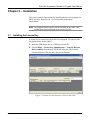
1
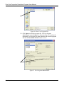
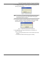
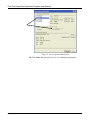
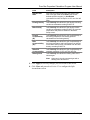
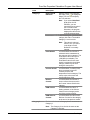
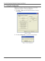
Part D301669X012 Form A6301 May 2014 Pure Gas Properties Calculation User Manual (for the FloBoss™ 107) Remote Automation Solutions Pure Gas Properties Calculation Program User Manual Revision Tracking Sheet May 2014 This manual may be revised periodically to incorporate new or updated information. The revision date of each page appears at the bottom of the page opposite the page number. A change in revision date to any page also changes the date of the manual that appears on the front cover. Listed below is the revision date of each page (if applicable): Page ii, 1 Initial Issue Rev May-14 Revision May-14 Jul-10 ii Pure Gas Properties Calculation Program User Manual Contents Chapter 1 – Introduction 1 1.1 Scope and Organization ...................................................................................................................... 1 1.2 Product Overview................................................................................................................................. 1 1.2.1 Pure Gas Properties Calculations........................................................................................... 2 1.2.2 Split Accumulator .................................................................................................................... 2 1.3 Program Requirements ........................................................................................................................ 2 1.3.1 License Keys........................................................................................................................... 3 Chapter 2 – Installation 5 2.1 Installing the License Key .................................................................................................................... 5 2.2 Downloading the Pure Gas Program ................................................................................................... 7 Chapter 3 – Configuration 11 3.1 Pure Gas Properties Screen .............................................................................................................. 12 3.1.1 Pure Gas Properties – General tab ...................................................................................... 14 3.1.2 Pure Gas Properties – Fluid Properties tab .......................................................................... 16 3.2 Split Accumulator Screen .................................................................................................................. 18 3.3 Saving the Configuration ................................................................................................................... 22 Chapter 4 – Reference 25 4.1 Point Type 27: Pure Gas Parameters ................................................................................................ 26 4.2 Point Type 28: Split Accumulator Parameters ................................................................................... 28 iii Rev May-14 Pure Gas Properties Calculation Program User Manual [This page is intentionally left blank.] Rev May-14 iv Pure Gas Properties Calculation Program User Manual Chapter 1 – Introduction This chapter describes the structure of this manual and presents an overview of the Pure Gas Properties Calculation for the FloBoss™ 107. 1.1 Scope and Organization This document serves as the user manual for the Pure Gas Properties Calculation user program, which is intended for use in FloBoss™ 107 (FB107). This manual describes how to download and configure the Pure Gas Properties Calculation user program (referred to as the “Pure Gas program” or “the program” throughout the rest of this manual). You access and configure the programs using ROCLINK 800 Configuration Software (version 1.87 or greater) loaded on a personal computer (PC) running Windows® 2000 (with Service Pack 2), Windows XP (with Service Pack 3), Windows Vista™ (32-bit), or Windows 7 (32-bit). The sections in this manual provide information in a sequence appropriate for first-time users. Once you become familiar with the procedures and the software running in a FB107, the manual becomes a reference tool. This manual has the following major sections: Chapter 1 – Introduction Chapter 2 – Installation Chapter 3 – Configuration Chapter 4 – Reference This manual assumes that you are familiar with the FB107 and its configuration. For more information, refer to the following manuals: 1.2 FloBoss 107 Flow Manager Instruction Manual (part D301232X012) ROCLINK 800 Configuration Software User Manual (for FB107) (part D301249X012) Product Overview The Pure Gas program enables an FB107 to calculate density, compressibility, and viscosity for a range of pure gases. A gas is considered pure if 100% of its composition is a single element. The program may be used for nearly pure gases where a single component accounts for 95% or more of the composition, but must be evaluated on a case-by-case basis by comparing the density calculated by the program against the density calculated by the NIST REFPROP application using the actual composition over the operating temperature and pressure range to determine if the error is within an acceptable tolerance for the application. 1 Rev May-14 Pure Gas Properties Calculation Program User Manual With the program installed, the FB107 reads flow inputs (differential pressure, static pressure, and temperature) and calculates flowing gas properties once every minute. In addition, the program performs split accumulations for up to five separate categories once every second. You configure the program and view the results using two program-specific screens (Pure Gas Properties and Split Accumulator). 1.2.1 Pure Gas Properties Calculations The program calculates pure gas density and compressibility at flowing and base conditions according to NIST 23. Heating value and viscosity are also calculated at flowing conditions according to NIST 23. While the program does not calculate the specific heat ratio, the defaults provided for each gas are calculated from NIST 23 Cp/Cv at 15°C and 101.325 kPa. The supported gases are: Oxygen Carbon Dioxide Nitrogen Argon Hydrogen Helium 1.2.2 Split Accumulator The program includes a Split Accumulator that allows you to configure up to five accumulation categories for use with the Pure Gas program. These user-configured accumulator categories allow differential billing to be performed on a flow or volume proportional basis. 1.3 Program Requirements The Pure Gas Properties Calculation version 1.00 is compatible with FB107 firmware version 1.32 and with version 1.87 (or greater) of ROCLINK 800 software. Each program requires you to install a software based license key to enable the calculations. The downloadable program is: File Name Program Number User-Defined Points Display Number PureGas_3.bin 3 27, 28 27, 28 Note: You must connect a PC to the FB107’s LOI port before starting the download. For information on viewing the memory allocation of user programs, refer to ROCLINK 800 Configuration Software User Manual (for FloBoss 107) (part D301249X012). Rev May-14 2 Pure Gas Properties Calculation Program User Manual 1.3.1 License Keys Some applications require that you install a license in the CPU to run the application. This license software is specific to these applications and is the property of the individual vendor (shown in the Vendor Name field on the License Key Administrator screens). RAS (and other authorized vendors) distributes software licenses on security-enhanced universal serial bus (USB) drives. You must install the following license keys to use the Pure Gas program: 3 Pure Gas License Key (FS1LK-9) Rev May-14 Pure Gas Properties Calculation Program User Manual [This page is intentionally left blank.] Rev May-14 4 Pure Gas Properties Calculation Program User Manual Chapter 2 – Installation This section provides instructions for installing the Pure Gas program into FB107 memory. Read Section 1.3 of this manual for program requirements. Note: The program and license key can be installed in any order. The manual shows the installation of the license key first. 2.1 Installing the License Key A license key is required to use the Pure Gas program. To install a USB key-based license on the FB107: 1. Insert the USB license key in a USB port on your PC. 2. Select Utilities > License Key Administrator > Transfer Between Device and Key from the ROCLINK 800 menu bar. The Transfer Licenses Between a Device and a Key screen displays. Figure 1. Transfer Licenses Between a Device and a Key 5 Rev May-14 Pure Gas Properties Calculation Program User Manual Note: This screen has three sections. The upper portion (Licenses on Device) shows any software licenses installed on the FB107. The middle portion (Licenses on Key) shows software licenses on the license key. The lower portion of the screen (License Key Event Log) provides a rolling log of the last eight events related to this license key. 3. Select the key-based licenses you want to transfer to the FB107 (PureGas, as shown in Figure 1). 4. Click Move to Device. ROCLINK moves one instance of the license from the key to the FB107 and updates the screen. Figure 2. License Installed Note: An FB107 can hold up to six different licenses, although you can install only one instance of each license on the FB107. When you click Move to Device, ROCLINK 800 moves only one instance of the license onto the FB107 and automatically decreases the license quantity on the USB key by one. 5. Verify the license name displays in the Licenses on Device section of the screen. Proceed to Section 2.2 to download the user program. Rev May-14 6 Pure Gas Properties Calculation Program User Manual 2.2 Downloading the Pure Gas Program This section provides instructions for installing the Pure Gas program into the Flash memory on the FB107. Note: Connect a PC to the FloBoss’s LOI port before starting the download. To download the user program: 1. Start and logon to ROCLINK 800. 2. Select ROC > Direct Connect to connect to the FloBoss unit. 3. Select Utilities > User Program Administrator from the ROCLINK menu bar. The User Program Administrator screen displays (see Figure 3): Figure 3. User Program Administrator 4. Click Browse in the Download User Program File frame. The Select User Program File screen displays (see Figure 4). 5. Select the path and user program file to download from the CD-ROM. (Program files are typically located in the Program Files folder on the CD-ROM). As Figure 4 shows, the screen lists all valid user program files with the .BIN extension: 7 Rev May-14 Pure Gas Properties Calculation Program User Manual Figure 4. Select User Program File 6. Click Open to select the program file. The User Program Administrator screen displays. As shown in Figure 5, note that the Download User Program File frame identifies the selected program and that the Download & Start button is active: Figure 5. User Program Administrator Rev May-14 8 Pure Gas Properties Calculation Program User Manual 7. Click Download & Start to begin loading the selected programs. The following message displays: Figure 6. Confirm Download Note: For the FB107, the factory has assigned program positions based on memory allocations. For this reason, the Pure Gas program automatically installs as program 3. 8. Click Yes to begin the download. During the download, the program performs a warm start, creates an event in the event log, and—when the download completes—displays the following message: Figure 7. ROCLINK 800 Download Confirmation 9. Click OK. The User Program Administrator screen displays (see Figure 8). Note that: The User Programs Installed in Device frame identifies the loaded program. The Status field indicates that the program is running. 9 Rev May-14 Pure Gas Properties Calculation Program User Manual Figure 8. User Program Administrator 10. Click Close and proceed to Section 3 to configure the program. Rev May-14 10 Pure Gas Properties Calculation Program User Manual Chapter 3 – Configuration After you have loaded the Pure Gas program, you configure it using ROCLINK 800 software. To do this, you use two program-specific screens (Pure Gas Properties and Split Accumulator): Use the Pure Gas Properties screen to enable the calculations and specify the pure gas type. Use the Split Accumulator screen to configure up to five accumulation categories for use with the Pure Gas program. Figure 9. ROCLINK 800 screen 11 Rev May-14 Pure Gas Properties Calculation Program User Manual 3.1 Pure Gas Properties Screen Use this screen and its tabs to enable the Pure Gas program calculations, define the pure gas type, and define properties of the selected pure gas. To access this screen: 1. From the Directory Tree, select User Program > Pure Gas. 2. Double-click Display #27, Pure Gas Properties. The Pure Gas Properties screen displays, showing the General tab: Figure 10. GOST Properties screen 3. Review the values in the following fields: Rev May-14 Field Description Point Number Indicates the specific meter run you want to define. Click to display additional runs for this device. Tag This read-only field shows the meter tag for the selected meter. The meter tag is defined in Meter>Setup. Description This read-only field shows the meter description for the selected meter. The meter description is defined in Meter>Setup. 12 Pure Gas Properties Calculation Program User Manual Field Description Active Flow Calculation This read-only field indicates the specific flow calculation in use. Active Properties Calculation This read-only field indicates the specific properties calculation in use. Differential Pressure This read-only field shows the flowing differential pressure. Units are InH2O or kPa. Static Pressure This read-only field shows the flowing static pressure. Units are PSIG, PSIA, kPa(a), or kPa(g). Temperature This read-only field shows the current flowing temperature. Units are Deg F or Deg C. Note: This field shows “Pure Gas” when the Pure Gas program is enabled. Note: The Pure Gas Properties screen—like other screens in this program—has a tab format. Sections 3.1.1 through 3.1.2 discuss the requirements for each tab on the Pure Gas Properties screen. 4. Click Apply to save any changes you have made to this screen. 5. Proceed to Section 3.1.1 to configure the General tab. 13 Rev May-14 Pure Gas Properties Calculation Program User Manual 3.1.1 Pure Gas Properties – General tab Use this tab (which displays when you access the Pure Gas Properties screen) to enable the Pure Gas program calculations and define the pure gas type. Figure 11. Pure Gas Properties, General tab Note: An error message (License Key Not Found) displays if the program license key is not properly installed. For more information, refer to Section 2.1, Installing the License Key. Rev May-14 14 Pure Gas Properties Calculation Program User Manual 1. Review the values in the following fields: Field Description Pure Gas Properties Sets the run status for Pure Gas program calculations. Valid selection are Enabled and Disabled. If Enabled, the program calculates fluid properties based on the calculation specified in the NIST 23 standard for the selected meter run. If Disabled, fluid properties are calculated by the AGA8 algorithm embedded in FB107 firmware or by a separate properties user program. Pure Gas Selection Specifies the type of pure gas flowing through the selected meter. Valid values are Oxygen, Carbon Dioxide, Nitrogen, Argon, Hydrogen, and Helium. 2. Click Apply to save any changes you have made to this screen. 3. Proceed to Section 3.1.2 to define fluid properties. 15 Rev May-14 Pure Gas Properties Calculation Program User Manual 3.1.2 Pure Gas Properties – Fluid Properties tab Use this tab to define the fluid properties and view the results of the calculation. To access this screen: 1. Select the Fluid Properties tab on the Pure Gas Properties screen. Figure 12. Pure Gas Properties, Fluid Properties tab Note: You must Enable the Pure Gas Properties field on the General tab in order to specify and view the parameters on the Fluid Properties tab. 2. Review the values in the following fields: Rev May-14 Field Description Viscosity Sets how the system determines the viscosity of the gas at flowing conditions. Valid values are: Calculate The program calculates the viscosity based on the selected gas. Enter Sets a user-defined viscosity. Use Default Viscosity is calculated from NIST 23 Cp/Cv at 15°C and 101.325 kPa. 16 Pure Gas Properties Calculation Program User Manual Field Description Specific Heat Ratio Sets how the system determines the specific heat ratio of the gas. Valid values Enter (sets a userdefined specific heat ratio), or Use Default (calculated from NIST 23 Cp/Cv at 15°C and 101.325 kPa). Flowing Density This read-only field shows the gas density at flowing conditions calculated according to NIST 23. Base Density This read-only field shows the gas density at base conditions calculated according to NIST 23 with base temperature and pressure defined on the Meter Setup screen. Flowing Compresibility (Zf) This read-only field shows the gas compressibility at the flowing temperature and flowing pressure calculated from the flowing density. Base Compressibility (Zb) This read-only field shows the gas compressibility at the base temperature and base pressure (as defined on the Meter Setup screen) calculated from the base density according to NIST 23. Standard Compressibility This read-only field shows the gas compressibility at standard conditions of 15°C and 101.325 kPa. Heating Value This read-only field shows the heating value of the selected gas. Note: Hydrogen is the only supported gas with a heating value other than 0. 3. Click Apply to save any changes you have made to this screen. 4. Click Close and proceed to Section 3.2 to configure the Split Accumulator screen. 17 Rev May-14 Pure Gas Properties Calculation Program User Manual 3.2 Split Accumulator Screen Use this screen to configure up to five accumulation categories for use with the Pure Gas program. These user-configured accumulator categories allow you to perform differential billing on a flow or volume proportional basis. To access this screen: 1. From the Directory Tree, select User Program > Pure Gas. 2. Double-click Display #28, Split Accumulator. The Split Acumulator screen displays: Figure 13. Split Accumulator screen Note: If you manually edit the fields (such as Current Volume and EOM Volume field values) in this display, the program uses the newly entered values in calculations. 3. Review the values in the following fields: Rev May-14 Field Description Point Number Selects the specific meter run you want to define. Click to display all meters in the device. 18 Pure Gas Properties Calculation Program User Manual Field Description Category 1 High Limit I/O Definition Sets the source of the category limit value. Click to display the Select TLP screen and specify the TLP selection. Note: If you select Undefined (0, 0, 0) for the I/O definition, you can manually enter a value in the Limit Value field. Otherwise, the program displays the value for the currently selected input. Limit Value Sets, in flowing units per hour, the category limit value. The default Category 1 Low Limit is 0. Note: This value is retrieved from the TLP you select in the High Limit I/O Definition or manually entered. Category 2 Flow Minutes This field shows the number of minutes that the instantaneous flow rate was in this category. The Flow Minute value rolls over at 1,000,000 (not editable). The Flow Minute value for the scan period is assigned to the highest category reached by the flow during the scan period. Current Volume This field shows, in flowing units, the accumulated volume at contract pressure and temperature for this category. The volume value rolls over at the specified Rollover Limit. Rollover Counter This field shows the number of times a rollover has occurred in the Current Volume field for this category. EOM Volume This field shows the value, in flowing minutes, of the Current Volume for this category at the end of the previous month. EOM Rollover Counter This field shows the value of the Rollover Counter for this category at the end of the previous month. The field definitions for Category 2 are the same as Category 1. Note: The Category 2 low limit is the same as the Category 1 high limit. 19 Rev May-14 Pure Gas Properties Calculation Program User Manual Field Description Category 3 The field definitions for Category 3 are the same as Category 1. Note: The Category 3 low limit is the same as the Category 2 high limit. Category 4 The field definitions for Category 4 are the same as Category 1. Note: The Category 4 low limit is the same as the Category 3 high limit. Category 5 The field definitions for Category 5 are the same as Category 1. Notes: The Category 5 low limit is the same as the Category 4 high limit. The High Limit I/O Definition field is not available because there is no accumulator upper limit for Category 5. The Limit Value field is not available because there is no accumulator upper limit for Category 5. Rollover Limit Sets the value at which the Current Volume for a category resets. The default is 1000000. Totals Flow Minutes This field shows the total of the Flow Minutes fields for Category 1 through 5. Current Volume This field shows the total of the Current Volumes fields for Category 1 through 5. Rollover Counter This field shows the total of the Rollover Counter fields for Category 1 through 5. EOM Volume This field shows the total of EOM Volume fields for Category 1 through 5. EOM Rollover Counter This field shows the total of EOM Rollover Counter fields for Category 1 through 5. Input Rate Sets the source of the instantaneous hourly flow rate. Click to display the Select TLP screen and specify the TLP selection. Note: If you select Undefined (0, 0, 0) for the I/O definition, you can manually enter a value in the Value field. Otherwise, the program displays the value for the currently selected input. Units Rev May-14 Sets the units of the Corrected Hourly Flow Rate. The default is CF. The units can be converted from the default value by entering the proper value in the Multiplier field. 20 Pure Gas Properties Calculation Program User Manual Field Description Multiplier Sets the source of the instantaneous flow multiplier value. This value is multiplied times the instantaneous flow Input Rate value and is used to change the engineering units of the accumulated volumes. Click to display the Select TLP screen and specify the TLP selection. Note: If you select Undefined (0, 0, 0) for the I/O definition, you can manually enter a value in the Value field. Otherwise, the program displays the value for the currently selected input. Corrected Hourly Flow Rate This field shows the result of the Input Rate value multiplied times the Multiplier value. This Corrected Hourly Flow Rate is used to calculate the Current Volume total. 4. Click Apply to save any changes you have made to this screen. 5. Proceed to Section 3.3 to save your configuration. 21 Rev May-14 Pure Gas Properties Calculation Program User Manual 3.3 Saving the Configuration Whenever you modify or change the configuration, save the final configuration to memory. To save the configuration: 1. Select ROC > Flags on the ROCLINK 800 menu bar. The Flags screen displays: Figure 14. Flags 2. Click Save Configuration. A verification message displays: Figure 15. Save Verification Rev May-14 22 Pure Gas Properties Calculation Program User Manual 3. Click Yes. When the save process completes, a confirmation message displays: Figure 16. Confirmation Note: Depending on the size and complexity of the user program, this process may take several minutes. When the process ends, the Status field on the Flags screen displays Completed. 4. Click Update on the Flags screen. This completes the process of saving your new configuration. Note: For archive purposes, you should also save this configuration to your PC’s hard drive or a removable media (such as a diskette or a flash drive) using the File > Save Configuration option on the ROCLINK 800 menu bar. 23 Rev May-14 Pure Gas Properties Calculation Program User Manual [This page is intentionally left blank.] Rev May-14 24 Pure Gas Properties Calculation Program User Manual Chapter 4 – Reference This section provides tables of information on the user-defined point types the Pure Gas Properties Calculation uses. 25 Point Type 27 (Pure Gas Parameters) Point Type 28 (Split Accum Params) Rev May-14 Pure Gas Properties Calculation Program User Manual 4.1 Point Type 27: Pure Gas Parameters Point type 27 contains the parameters for configuring the Pure Gas program and viewing calculated property values. Each logical corresponds to a meter run logical. The program maintains up to four logicals of this point. Point Type 27:Pure Gas Parameters Parm # Name Access Data Type Length Range Default Description Logical 0 = “Meter #1”, 0 Point Tag ID R/W AC 10 10 Characters Logical 1 = “Meter #2”, Logical 2 = “Meter #3”, Point tag description. Logical 3 = “Meter #4” Pure Gas Calculation Enable 1 Enable Pure Gas R/W UI8 1 0-1 0 0 = Calculation Disabled 1 = Calculation Enabled Gas Selection 2 Selected Pure Gas R/W UI8 1 0-5 0 0 = Oxygen 1 = Carbon Dioxide 2 = Nitrogen 3 = Argon 4 = Hydrogen 5 = Helium Calculate Viscosity 3 Enter/Calc Viscosity R/W UI8 1 0-2 0 4 Pure Gas Viscosity R/W FL 4 Any valid floating point number 1.356e-5 Lbm/Ft-Sec 5 Enter/Calc SpecHeat R/W UI8 1 0, 2 0 0 = Enter Value 1 = Calculate Value 2 = Use Default Value Viscosity Enter/Use Defaults for Specific Heat Ratio Rev May-14 0 = Enter Value 2 = Use Defaults 26 Pure Gas Properties Calculation Program User Manual Point Type 27:Pure Gas Parameters Parm # Name Access Data Type Length Range Default 6 Specific Heat Ratio RW FL 4 Any valid floating point number greater than 0.0 1.3972 7 Heating Value R/O FL 4 Any valid floating point number greater than 0.0 0 27 Description Specific Heat Ratio Heating Value Rev May-14 Pure Gas Properties Calculation Program User Manual 4.2 Point Type 28: Split Accumulator Parameters Point type 28 contains the parameters for configuring the Split Accumulator screen. The program maintains up to one logical of this point. Point Type 28:Split Accumulator Parameters Parm # Name Access Data Type Length Range Default 0 Point Tag ID R/W AC 10 10 Characters “SplitAccum” 1 Categ.1 HLim Input R/W TLP 3 Any valid Type, Logical, Parameter group 0,0,0 Category 1 High Limit Input 2 High Limit R/W FL 4 Any valid floating point number 0.0 Category 1 High Limit Value 3 Categ.2 HLim Input R/W TLP 3 Any valid Type, Logical, Parameter group 0,0,0 Category 2 High Limit Input 4 High Limit R/W FL 4 Any valid floating point number 0.0 Category 2 High Limit Value 5 Categ.3 HLim Input R/W TLP 3 Any valid Type, Logical, Parameter group 0,0,0 Category 3 High Limit Input 6 High Limit R/W FL 4 Any valid floating point number 0.0 Category 3 High Limit Value 7 Categ.4 HLim Input R/W TLP 3 Any valid Type, Logical, Parameter group 0,0,0 Category 4 High Limit Input 8 High Limit R/W FL 4 Any valid floating point number 0.0 Category 4 High Limit Value 9 Categ.1 Minutes R/W FL 4 Any valid floating point number 0.0 Category 1 Minutes 10 Categ.2 Minutes R/W FL 4 Any valid floating point number 0.0 Category 2 Minutes 11 Categ.3 Minutes R/W FL 4 Any valid floating point number 0.0 Category 3 Minutes 12 Categ.4 Minutes R/W FL 4 Any valid floating point number 0.0 Category 4 Minutes Rev May-14 Description Point tag description. 28 Pure Gas Properties Calculation Program User Manual Point Type 28:Split Accumulator Parameters Parm # Name Access Data Type Length Range Default 13 Categ.5 Minutes R/W FL 4 Any valid floating point number 0.0 Category 5 Minutes 14 TTL Minutes R/W FL 4 Any valid floating point number 0.0 Total Minutes 15 Categ.1 Cur Volume R/W FL 4 Any valid floating point number 0.0 Category 1 Current Volume 16 Categ.2 Cur Volume R/W FL 4 Any valid floating point number 0.0 Category 2 Current Volume 17 Categ.3 Cur Volume R/W FL 4 Any valid floating point number 0.0 Category 3 Current Volume 18 Categ.4 Cur Volume R/W FL 4 Any valid floating point number 0.0 Category 4 Current Volume 19 Categ.5 Cur Volume R/W FL 4 Any valid floating point number 0.0 Category 5 Current Volume 20 TTL Cur Volume R/W FL 4 Any valid floating point number 0.0 Total Current Volume 21 Categ.1 Cur Roll Ctr R/W UI16 2 Any valid floating point number 0 Category 1 Current Rollover Counter 22 Categ.2 Cur Roll Ctr R/W UI16 2 Any valid floating point number 0 Category 2 Current Rollover Counter 23 Categ.3 Cur Roll Ctr R/W UI16 2 Any valid floating point number 0 Category 3 Current Rollover Counter 24 Categ.4 Cur Roll Ctr R/W UI16 2 Any valid floating point number 0 Category 4 Current Rollover Counter 25 Categ.5 Cur Roll Ctr R/W UI16 2 Any valid floating point number 0 Category 5 Current Rollover Counter 26 TTL Cur Roll Ctr R/W UI16 2 Any valid floating point number 0 Total Current Rollover Counter 27 Categ.1 EOM Volume R/W FL 4 Any valid floating point number 0.0 Category 1 End of Month Volume 28 Categ.2 EOM Volume R/W FL 4 Any valid floating point number 0.0 Category 2 End of Month Volume 29 Description Rev May-14 Pure Gas Properties Calculation Program User Manual Point Type 28:Split Accumulator Parameters Parm # Name Access Data Type Length Range Default 29 Categ.3 EOM Volume R/\W FL 4 Any valid floating point number 0.0 Category 3 End of Month Volume 30 Categ.4 EOM Volume R/\W FL 4 Any valid floating point number 0.0 Category 4 End of Month Volume 31 Categ.5 EOM Volume R/\W FL 4 Any valid floating point number 0.0 Category 5 End of Month Volume 32 TTL EOM Volume R/\W FL 4 Any valid floating point number 0.0 Total End of Month Volume 33 Categ.1 EOM Roll Ctr R/\W UI16 2 Any valid floating point number 0 Category 1 End of Month Rollover Counter 34 Categ.2 EOM Roll Ctr R/\W UI16 2 Any valid floating point number 0 Category 2 End of Month Rollover Counter 35 Categ.3 EOM Roll Ctr R/\W UI16 2 Any valid floating point number 0 Category 3 End of Month Rollover Counter 36 Categ.4 EOM Roll Ctr R/\W UI16 2 Any valid floating point number 0 Category 4 End of Month Rollover Counter 37 Categ.5 EOM Roll Ctr R/\W UI16 2 Any valid floating point number 0 Category 5 End of Month Rollover Counter 38 TTL EOM Roll Ctr R/\W UI16 2 Any valid floating point number 0 Total End of Month Rollover Counter 39 Rollover Limit R/\W FL 4 Any valid floating point number 1000000.0 Rollover Limit 40 Multiplier Input R/\W TLP 3 Any valid Type, Logical, Parameter group 0,0,0 Multiplier Input 41 Multiplier Value R/\W FL 4 Any valid floating point number 1.0 Multiplier Value 42 Inst Hrly Flow Input R/\W TLP 3 Any valid Type, Logical, Parameter group 47,0,2 Instantaneous Hourly Flow Input 43 Inst Hourly Flow R/\W FL 4 Any valid floating point number 0.0 Instantaneous Hourly Flow Value Rev May-14 Description 30 Pure Gas Properties Calculation Program User Manual Point Type 28:Split Accumulator Parameters Parm # Name Access Data Type Length Range 44 Inst Hrly Flow Units R/\W AC10 10 10 Characters 45 Corrected Hrly Flow R/\W FL 4 Any valid floating point number 31 Default “CF 0.0 Description “ Instantaneous Hourly Flow Units Corrected Hourly Flow Rev May-14 Pure Gas Properties Calculation Program User Manual Headquarters: Emerson Process Management Remote Automation Solutions 6005 Rogerdale Road Houston, TX 77072 U.S.A. T +1 281 879 2699 | F +1 281 988 4445 www.EmersonProcess.com/Remote Europe: Emerson Process Management Remote Automation Solutions Emerson House Unit 8, Waterfront Business Park Dudley Road, Brierly Hill Dudley UK DY5 1LX T +44 1384 487200 | F +44 1384 487258 www.EmersonProcess.com/Remote North American/Latin America: Emerson Process Management Remote Automation Solutions 6005 Rogerdale Road Houston TX USA 77072 T +1 281 879 2699 | F +1 281 988 4445 www.EmersonProcess.com/Remote Middle East/Africa: Emerson Process Management Remote Automation Solutions Emerson FZE P.O. Box 17033 Jebel Ali Free Zone – South 2 Dubai U.A.E. T +971 4 8118100 | F +971 4 8865465 www.EmersonProcess.com/Remote Asia-Pacific: Emerson Process Management Remote Automation Solutions 1 Pandan Crescent Singapore 128461 T +65 6777 8211| F +65 6777 0947 www.EmersonProcess.com/Remote Remote Automation Solutions © 2010-2014 Remote Automation Solutions, a business unit of Emerson Process Management. All rights reserved. Remote Automation Solutions, a business unit of Emerson Process Management, shall not be liable for technical or editorial errors in this manual or omissions from this manual. REMOTE AUTOMATION SOLUTIONS MAKES NO WARRANTIES, EXPRESSED OR IMPLIED, INCLUDING THE IMPLIED WARRANTIES OF MERCHANTABILITY AND FITNESS FOR A PARTICULAR PURPOSE WITH RESPECT TO THIS MANUAL AND, IN NO EVENT SHALL REMOTE AUTOMATION SOLUTIONS BE LIABLE FOR ANY INCIDENTAL, PUNITIVE, SPECIAL OR CONSEQUENTIAL DAMAGES INCLUDING, BUT NOT LIMITED TO, LOSS OF PRODUCTION, LOSS OF PROFITS, LOSS OF REVENUE OR USE AND COSTS INCURRED INCLUDING WITHOUT LIMITATION FOR CAPITAL, FUEL AND POWER, AND CLAIMS OF THIRD PARTIES. Bristol, Inc., Bristol Canada, BBI SA de CV and Emerson Process Management Ltd, Remote Automation Solutions (UK), are wholly owned subsidiaries of Emerson Electric Co. doing business as Remote Automation Solutions, a business unit of Emerson Process Management. FloBoss, ROCLINK, Bristol, Bristol Babcock, ControlWave, TeleFlow, Helicoid, OpenEnterprise, and METCO are trademarks of Remote Automation Solutions. AMS, PlantWeb and the PlantWeb logo are marks of Emerson Electric Co. The Emerson logo is a trademark and service mark of the Emerson Electric Co. All other marks are property of their respective owners. The contents of this publication are presented for informational purposes only. While every effort has been made to ensure informational accuracy, they are not to be construed as warranties or guarantees, express or implied, regarding the products or services described herein or their use or applicability. Remote Automation Solutions reserves the right to modify or improve the designs or specifications of such products at any time without notice. All sales are governed by Remote Automation Solutions’ terms and conditions which are available upon request. Remote Automation Solutions does not assume responsibility for the selection, use or maintenance of any product. Responsibility for proper selection, use and maintenance of any Remote Automation Solutions product remains solely with the purchaser and end-user.