1
AR-ALPHA
Digital Processing
Communications Receiver
Operating Manual v.2.1
AOR, LTD.
Table of Contents
1. Introduction ---------------------------------------------------------------------------------------------------------- 4
1-1 Introduction ---------------------------------------------------------------------------------------------- 4
1-2 Caring for your radio ---------------------------------------------------------------------------------- 6
1-3 Please note these operating procedures ---------------------------------------------------------- 7
1-4 Accessories supplied ---------------------------------------------------------------------------------- 7
1-5 Controls and functions ----------------------------------------------------------------------------------12
Front Panel
----------------------------------------------------------------------------------12
1-5-1 Keypad
----------------------------------------------------------------------------------13
1-5-2 Summary of keys
----------------------------------------------------------------------13
Rear Panel
----------------------------------------------------------------------------------28
2. Getting Started
----------------------------------------------------------------------------------------------31
2-1 Preparing the AR-ALPHA for operation ----------------------------------------------------------31
2-1-1 Connecting the antenna
----------------------------------------------------------31
2-1-2 Connecting power ----------------------------------------------------------------------32
2-2 Switching on for the first time ----------------------------------------------------------------------32
2-3 Squelch Circuit
----------------------------------------------------------------------------------33
2-4 VFO selection
----------------------------------------------------------------------------------33
2-4-1 Tuning frequency
----------------------------------------------------------------------34
2-4-1-1 Entering a frequency using the numeric keypad
----------34
2-4-1-2 Changing frequency using the main tuning dial
----------35
2-4-1-3 Changing frequency using the arrow keys
----------------------35
2-5 Changing receive mode
----------------------------------------------------------------------36
2-5-1 Auto mode selection ----------------------------------------------------------------------37
2-5-2 Receive mode selection
----------------------------------------------------------37
2-5-3 Additional decoding modes ----------------------------------------------------------39
2-6 Changing tuning step size
----------------------------------------------------------------------41
2-7 IF bandwidth ----------------------------------------------------------------------------------------------42
2-7-1 Manually selecting IF band width
----------------------------------------------43
2-8 Attenuator
----------------------------------------------------------------------------------------------43
2-9 Offset
----------------------------------------------------------------------------------------------44
2-9-1 Using pre-programmed frequency offset data
----------------------------------44
2-9-2 Entering new frequency offset data
----------------------------------------------45
2-9-3 Activating frequency offset
----------------------------------------------------------46
2-9-4 Monitoring the offset frequency
----------------------------------------------46
2-9-5 Deactivating frequency offset ----------------------------------------------------------46
3. Spectrum Display
----------------------------------------------------------------------------------------------47
3-1 LCD Display Screen (in VFO spectrum analyzer mode)
----------------------------------47
3-1-1 Operation mode display
----------------------------------------------------------47
3-1-2 Basic operation display
----------------------------------------------------------48
3-1-3 Spectrum display (example) ----------------------------------------------------------49
3-2 Display span setting ----------------------------------------------------------------------------------50
3-2-1 Setting the display span
----------------------------------------------------------52
4. Memory channels
----------------------------------------------------------------------------------------------53
4-1 Memory Bank and Memory Channel
----------------------------------------------------------54
4-2 Storing VFO frequency and data into memory
----------------------------------------------55
4-3 Memory read “M.RD” --------------------------------------------------------------------------------- 56
1
4-4 Memory Mode
----------------------------------------------------------------------------------57
4-4-1 From Bank List screen to MemBank screen or Browser ----------------------58
4-4-2 From Bank List to MemCh List
----------------------------------------------60
4-4-3 From MemCh List to MemCh **.** Browser
----------------------------------61
5. SCAN – scanning memory channels
----------------------------------------------------------------------64
5-1 SCAN – outline introduction
----------------------------------------------------------------------64
5-2 Starting SCAN
----------------------------------------------------------------------------------64
5-3 SCAN operation
----------------------------------------------------------------------------------65
5-3-1 Changing scan direction
----------------------------------------------------------66
5-4 Selecting a SCAN bank
----------------------------------------------------------------------66
5-5 Bank link
----------------------------------------------------------------------------------------------67
5-5-1 Setting Bank link
----------------------------------------------------------------------67
5-6 Select SCAN ----------------------------------------------------------------------------------------------67
5-6-1 Adding select scan channels in memory read
----------------------------------67
5-6-2 Start select scan
----------------------------------------------------------------------68
5-7 Channel Pass
----------------------------------------------------------------------------------69
5-7-1 Setting channel pass
----------------------------------------------------------69
6. Search
----------------------------------------------------------------------------------------------------------70
6-1 Search setting
----------------------------------------------------------------------------------70
6-1-1 Setting
----------------------------------------------------------------------------------70
6-1-2 Search Bank Browser setting ----------------------------------------------------------71
6-1-3 Start search
----------------------------------------------------------------------71
6-2 Search Group
----------------------------------------------------------------------------------73
6-2-1 Setting Search Group
----------------------------------------------------------73
7. FFT Search ----------------------------------------------------------------------------------------------------------75
7-1 FFT Search setting
----------------------------------------------------------------------------------75
7-7-1 FFT Search Screen ----------------------------------------------------------------------76
8. Miscellaneous Settings
----------------------------------------------------------------------------------78
8-1 Soft key registration ----------------------------------------------------------------------------------78
8-1-1 Operation of soft keys
----------------------------------------------------------78
8-1-2 Soft key registration ----------------------------------------------------------------------79
8-2 Voice Recording
----------------------------------------------------------------------------------79
8-2-1 Recording ----------------------------------------------------------------------------------80
8-2-2 Stop recording
----------------------------------------------------------------------80
8-2-3 Playback audio
----------------------------------------------------------------------80
8-2-4 Changing record channel
----------------------------------------------------------81
8-3 Data Editor ----------------------------------------------------------------------------------------------81
8-3-1 Moving memory bank
----------------------------------------------------------82
8-3-2 Copying memory bank
----------------------------------------------------------83
8-3-3 Moving search bank ----------------------------------------------------------------------83
8-3-4 Copying search bank
----------------------------------------------------------84
8-3-5 Moving memory channel
----------------------------------------------------------85
8-3-6 Copying memory channel
----------------------------------------------------------85
8-3-7 Copying scan group data
----------------------------------------------------------86
8-3-8 Copying scan group data
----------------------------------------------------------87
8-3-9 Moving search group data
----------------------------------------------------------88
8-3-10 Copying search group
----------------------------------------------------------88
2
8-3-11 Moving recorded voice data ----------------------------------------------------------89
8-3-12 Deleting memory bank
----------------------------------------------------------89
8-3-13 Deleting search bank
----------------------------------------------------------90
8-3-14 Deleting memory channel
----------------------------------------------------------90
8-3-15 Deleting memory pass channel
----------------------------------------------91
8-3-16 Deleting all search pass channels
----------------------------------------------91
8-3-17 Deleting all memory banks ----------------------------------------------------------91
8-3-18 Deleting all search banks
----------------------------------------------------------91
8-3-19 Deleting voice record channel
----------------------------------------------92
8-3-20 Deleting all voice record data
----------------------------------------------92
8-4 Configuration settings ----------------------------------------------------------------------------------92
8-4-1 Configure backlight ----------------------------------------------------------------------93
8-4-2 Configure beep
----------------------------------------------------------------------94
8-4-3 Configure RF-Gain (Radio Frequency Gain)
----------------------------------94
8-4-4 Configure reference signal input
----------------------------------------------95
8-4-5 Video display & format
----------------------------------------------------------95
8-4-6 Configure I/Q output bandwidth
----------------------------------------------96
8-4-7 Configure Voice squelch level ----------------------------------------------------------97
8-4-7-1 Configure Voice level and delay time ----------------------------------97
8-4-8 Configure PC interface
----------------------------------------------------------98
8-4-9 Configure Sleep Timer
----------------------------------------------------------98
8-4-10 Configure Priority function ----------------------------------------------------------99
8-4-10-1 Setup ----------------------------------------------------------------------99
8-4-10-2 Activating priority function --------------------------------------------100
9. Computer control
---------------------------------------------------------------------------------------------101
9-1 How to send a control command
---------------------------------------------------------101
9-2 Power on
---------------------------------------------------------------------------------------------101
9-3 Detailed control command list of the AR-ALPHA ---------------------------------------------102
10. Specifications -------------------------------------------------------------------------------------------------------121
11. I/Q digital output in details for developers
12. Reset
---------------------------------------------------------123
---------------------------------------------------------------------------------------------------------129
13. Firmware upgrade
---------------------------------------------------------------------------------------------130
14. Optional Accessories ---------------------------------------------------------------------------------------------134
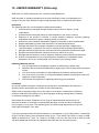
15. Limited Warranty (USA only) ---------------------------------------------------------------------------------135
3
1 Introduction
1-1 Introduction
Thank you for purchasing the AR-ALPHA Digital Processing Communications receiver. The
AR-ALPHA was designed using the very latest technology to ensure the highest levels of
performance and reliability. To get the best possible results from your AR-ALPHA, we strongly
recommend that you read this manual to familiarize yourself with the receiver and its many
functions.
Although carefully designed, this receiver (and most other receivers) generates internal noises
known as spurious emissions. They are a product of the receiver’s circuitry, and their presence
does not represent a defect. Other apparent defects may be due to unintentional misoperation of
the receiver. If you believe there is a problem, carefully read the entire manual before contacting
your dealer for advice.
It is acknowledged that sections of this manual are repetitive, this is to enable the manual to be
used as a quick reference book (you don’t have to read it from cover to cover at one time). Due to
the international nature of the product, some graphics may contain Japanese characters.
Every effort has been made to make this manual correct and up to date. Due to continuous
development of the receiver, there may be error or omission anomalies and this is acknowledged.
© This manual is protected by copyright AOR, LTD. 2007. No information contained in this manual
may be copied or transferred by any means without the prior written consent of AOR, LTD. AOR
and the AOR logo are trademarks of AOR, LTD. All other trademarks and names are
acknowledged.
4
Main features:
Wide frequency coverage: 10 kHz to 3.5 GHz, with no interruptions (USA consumer version
has cellular telephone frequencies blocked)
Zero-IF frequency (for the 3rd IF)
DDS (Direct Digital Synthesizer) local oscillator
TV reception in NTSC, PAL, and SECAM formats
I/Q output with 1 MHz bandwidth
Multi-mode unit capable of receiving AM (Synchronous), ISB, RZ-SSB, USB, LSB, CW, WFM
including FM stereo (when using optional headphones), NFM and APCO P25 digital
6-inch TFT color panel can display received video signals or depict spectrum activity over a
wide choice of bandwidths including a “waterfall” function to show signal activity over a
specified time period
Composite video output on the rear panel of the unit
Selectable IF bandwidths: 200 Hz, 500 Hz, 1 kHz, 3 kHz, 6 kHz, 15 kHz, 30 kHz, 100 kHz,
200 kHz and 300 kHz and the ability to shift the IF
CTCSS and DCS selectable squelch functions
DTMF tone decode
Built-in voice-inversion descrambling (Not available on USA consumer version)
CW pitch control, AGC, AFC
Auto-notch feature
User selectable spectrum display function from 250 kHz through 10 MHz in 1 kHz increments.
Above 10 MHz bandwidth, it can display 20 MHz, 50 MHz, 100 MHz or 1 GHz, but above 20
MHz bandwidth, no audio will be available
RBW (Resolution bandwidth) is also user-selectable in increments of 1 kHz, 4 kHz, 32 kHz,
64 kHz and 128 kHz
Fast Fourier Transform (FFT) spectrum display
Analog output for DRM PC receiver
RS-232C and USB 2.0 interfaces
Two antenna ports (one SO-239 and one Type N). Up to four antennas may be selected
through the receiver’s controls with the optional AS5000 antenna relay switch
Use desktop or 19” rack mount
Five VFOs, 2,000 alphanumeric memories
Digital Voice Recording up to 53 minutes
5
1-2 Caring for your radio
There are no internal operator adjustments. In the unlikely event of service being required, please
contact your dealer for technical assistance.
Do not use or leave the receiver in direct sunlight (especially the LCD). It is best to avoid locations
where excessive heat, humidity, dust and vibration are expected. Always keep the AR-ALPHA
free from dust and moisture. Use a soft, dry cloth to gently wipe the set clean, never use abrasive
cleaners or organic solvents which may damage certain parts.
Treat the AR-ALPHA with care, avoid the spilling or leakage of liquids into the receiver. Special
care should be taken to avoid liquid entering around the controls, through the speaker grille or
through the connection jacks.
The AR-ALPHA is designed for operation from a high quality regulated DC supply of 12 to 14 V,
which should be capable of supplying at least 2.2A. Never connect the AR-ALPHA directly to an
AC outlet. The polarity of the DC input jack is clearly marked, the chassis of the receiver is at
negative ground.
SAFETY NOTICE – Always disconnect the power supply from the AC outlet when not in
use. If used mobile, it should be noted that the AR-ALPHA has NOT
been manufactured or tested to meet any specific mobile safety
requirements.
The AR-ALPHA has no internal user adjustable parts.
If using the AR-ALPHA in a base station situation, the best short wave reception is usually
achieved by using a separate external earth (ground) rod, however, consider the implications
carefully if the AC supply at your location uses a Protective Multiple Earth (PME) system. If in
doubt consult a qualified electrician. Never earth (or ground) to a gas pipe!
The AR-ALPHA has two antenna connectors for all frequencies. These are intended for
connection to a 50Ω (unbalanced) coaxial fed antenna such as a discone, dipole, unipole, Yagi,
etc. When locating the antenna, avoid power cables. Ensure that you do not confuse the antenna
connection and the 10 MHz frequency reference connector as they are in close proximity.
6
1-3 Please note these operating procedures
1. Certain key operations are acted upon when the key is RELEASED, not while it is
pressed. Allow time for the AR-ALPHA to register and process each action before
pressing another key.
2. The keylock (K.LOCK) is intentionally made difficult to operate to prevent accidental
operation. To release the keylock, the K.LOCK key must be held for more than one
second, the key icon on the LCD confirms operation. The K.LOCK is disabled during
keying sequences (such as when entering frequencies).
3. Currently displayed VFO data is saved at power down (to increase speed of the
operation and to reduce write cycles). For this reason, if the AR-ALPHA is powered down
using the MAIN POWER (rear panel) switch or external power is removed, the last
displayed frequency will be lost and the frequency used prior to this will be displayed the
next time the receiver is powered up.
1-4 Accessories supplied
The following items are included in the shipping carton:
1
AR-ALPHA receiver
2.
DC power cable
3. Operating manual (this booklet)
4 Rack mount handles and screws
7
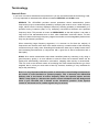
Terminology
Search & Scan
If you have not used a wide band receiver before or you are not familiar with the terminology used,
it is very important to understand the difference between SEARCH and SCAN modes.
SEARCH: The AR-ALPHA provides several operations where transmissions (active
frequencies) may be automatically located by sweeping the receiver over a wide frequency
range, either from the currently displayed frequency traveling upwards (or downwards) in a
specified tuning increment (step) or by sweeping over-and-over between two specified
frequency limits. This process is known as SEARCHING, as the title implies, it can take a
long time to find transmissions due to their ‘often intermittent’ and brief nature. For this
reason it is best to slice large frequency ranges into smaller, more manageable pieces where
they may be intensely searched.
When examining large frequency segments, it is common to find that the majority of
frequencies are inactive at the time of the search and only a small number of the remaining
constitute what you really want. Searching still remains the best way to initially locate active
and interesting transmissions (in conjunction with a good list of active frequencies and a
band plan).
SCAN: Once active transmissions have been identified (either by searching or by using a
good frequency guide), it is more efficient to store the data into memories which can be
rapidly and automatically monitored in succession, stopping when activity is encountered.
This is a much more efficient means of monitoring the most wanted frequencies you have
targeted, that is, what you most want to hear. By contrast, searching is very inefficient for
day-to-day monitoring.
Note: It is very important that the squelch is advanced to cancel background noise for
the search & scan functions to operate properly. This is because the AR-ALPHA
believes that it has found an active frequency when the squelch opens and the
“BUSY” lamp lights up. Advance the squelch control clockwise until the background
noise is just cancelled, this is known as the “threshold” position. If the squelch
control is advanced too far, weaker signals may be missed.
8
More details about the remarkable features of the AR-ALPHA
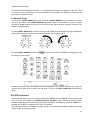
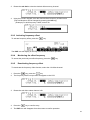
Zero – IF (Zero Intermediate Frequency)
Block diagram 1 shows a conventional triple conversion super heterodyne analog receiver and the
3rd IF frequency is 455 kHz. Due to its frequency configuration, some “image” signals may be
received.
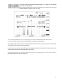
Block diagram 2 shows the AOR Zero-IF digital receiver.
The 10.7 MHz 2nd IF analog signal is fed to the ADC (Analog to Digital Converter) to be digitized
and the signal is digitally mixed with the 10.7 MHz local oscillator. The signal is digitally processed,
and the 3rd IF signal becomes zero (0). By utilizing this technique, no image signal will be present.
DDS (Direct Digital Synthesizer)
The AR-ALPHA uses high speed DDS for the 1st local oscillator. Unlike standard PLL (Phased
Locked Loop) circuits for the local oscillator, DDS enables very fast scanning as it quickly
generates signals controlled by the CPU (Micro Processor).
9
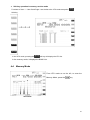
I/Q Digital Output
I/Q stands for In-Phase/Quadrature -Phase.
At the 3rd IF stage, the AR-ALPHA provides an I/Q output. The I/Q digital signal consists of two (2)
different digital signals that are phase-shifted 90 degrees.
The I/Q output is provided through a continuous isochronous USB 2.0 standard interface. By
using the I/Q digital output, the streamed data can be stored on a PC hard disk for future signal
analysis.
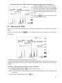
FFT (Fast Fourier Transform)
The AR-ALPHA utilizes FFT (Fast Fourier Transform) technology for the spectrum display feature.
FFT in the AR-ALPHA refreshes the spectrum display more than 10 times per second during a 10
MHz sweep (at 500 Hz RBW). The AR-ALPHA can display a wide range sweep up to 1 GHz.
Receive modes / Additional features
WFM (Wide FM)
Stereo sound (auto detected), Selectable de-emphasis 50 uS/75 uS
Stereo output is available from the headphone jack using optional stereo headphones or
from the RCA jacks on the rear panel (optional stereo amplifier required)
NFM (Narrow FM)
Built-in DCS (Digital Coded Squelch)
Built-in CTCSS (Continuous Tone Coded Squelch System)
Built-in Voice Inversion Descrambler (4,500 Hz +/- 2,000 Hz) (Not available on USA
consumer version)
Built-in APCO25 (P-25) decoder (conventional mode only)
Built-in AFC (Automatic Frequency Control)
10
AM (Amplitude Modulation)
Envelope Detection (Normal AM decoder)
Synchronous Detection
1. DSB (Double Side Band) synchronous
2. SSB (Single Side Band) USB/LSB (Upper Side Band/Lower Side Band) selectable
synchronous
3. Side Band Diversity
AGC (Automatic Gain Control) mode/Manual RF gain mode
SSB (Single Side Band)
USB/LSB selectable
AGC mode/Manual RF gain mode
Sharp shape factor BPF (Band Pass Filter)
ISB (Independent Side Band)
Simultaneously decoded LSB and USB (Stereo Output)
AGC mode/Manual RF gain mode
CW (Continuous Wave)
Built-in narrow band IF filters, 200 Hz/500 Hz
CW stereo effect 200 Hz IF filter (Right +100 Hz/-50 Hz,
Left +50 Hz/-100 Hz) (,headphones required)
Adjustable tone pitch, 600 Hz +/- 300 Hz
VIDEO
TV reception in NTSC, PAL, or SECAM formats
RZ-SSB (Real Zero SSB)
Decodes AM signal with FM decoder (without AGC) by using phase signal
Effective against phasing or interference
NB (Noise Blanker)
Operates in AM, SSB, ISB and RZSSB mode
Auto Notch Filter
Adaptive Digital Noise Filter
11
IF Shift
Shift width: +/- 1.200 Hz
Operates in SSB and AM modes
VSQ (Voice Squelch)
Utilize FFT and LMS (The Least-Mean-Square) algorithm
DVR (Digital Voice Recorder)
Records up to 53 minutes (up to 12 minutes in WFM mode)
Captures audio up to 12 seconds prior to the start of recording
Analog output for DRM (Digital Radio Mondiale)
6 kHz IF (I/Q) analog output for DRM PC receiver
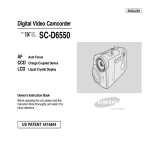
1-5 Controls & functions
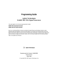
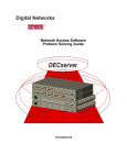
Controls are located on the front with most connectors on the rear of the AR-ALPHA.
A brief identification is given here:
Front Panel
①
②
③
④
⑤
⑥
⑦
⑧
⑨
⑩
⑪
⑫
⑬
Internal speaker
Analog S-meter
Status Indicators
LCD screen
Soft Keys
Main control keys
Front accessory connector
Headphone Jack
Main Dial knob
Sub Dial knob
Sub dial keys
Squelch control knob
AF Gain (Volume) control knob
12
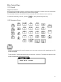
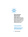
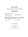
Main Control Keys
1-5-1 Keypad
Keypad conventions
Most keys have secondary functions, which are printed on the panel. However, due to the restrictions
of available space, not all functions can be shown on the keypad.
The secondary functions of the AR-ALPHA are indicated with white characters above each key.
To access the secondary function, press the
key, then press the respective key.
1-5-2 Summary of keys
POWER
Press and hold this key for one (1) second to turn on power to the unit. After initializing, the LCD
screen will appear.
To turn power off, press and hold this key for 2 seconds. A “power off” message will appear on the
screen and the power to the unit will turn off.
13
K.LOCK
Press this key when you do not wish an important frequency to be lost or the
AR-ALPHA to be incorrectly set to a different frequency.
To exit from the key lock function, press and hold this key for 2 seconds.
MONI
The monitor key manually overrides the squelch so that you may monitor a weak signal.
FUNC
The function key is used to select the secondary functions of the keypad.
VFO / WSP
Press this key to select the VFO mode. There are 5 VFOs (VFO-A through VFO-E) you may access
in the AR-ALPHA.
Press the
key, then press this key to enter the WSP (Wide Span) mode.
The WSP icon appears on the left of the frequency display. The AR-ALPHA can display up to 1 GHz
of frequency bandwidth. To exit the WSP mode, press the VFO key.
SRCH / SRCH.E
Press this key to select the NORMAL SEARCH mode.
To initiate a normal search, press and hold the SRCH key for 2 seconds.
Press the
key, then press and hold this key for 2 seconds to enter the Search Environment
set mode.
To exit from the Search mode, press the VFO key.
14
SCAN / MEMO/E
Press this key to initiate SCAN.
To set the scan mode, press and hold the SCAN key for 2 seconds.
Press the
key, then press and hold this key for 2 seconds to enter the Scan Environment
set mode.
To exit from the Scan mode, press the VFO key.
MHz / ENT
Press this key to have the AR-ALPHA accept data entry.
When entering a frequency in MHz, use numeric keys followed by this key.
KHz / S.ENT
When entering a frequency in kHz, use numeric keys followed by this key.
Press this key to accept frequency step entry.
STEP/ S.ADJ
Press this key to enter frequency step.
Press the
key, then press this key to go into the Frequency Step Adjust mode.
MODE / D.OPTION
Press this key to display the receive mode selection menu. Then select the desired receive mode
by rotating the Sub Dial Knob. Press the MHz key to confirm entry.
Any receive mode may be selected for any frequency within the receiver’s frequency coverage
range.
Press and hold this key for 2 seconds to go into the Auto-Mode.
Simple Select Mode
15
To switch the Mode selection to “Advanced”, press the MODE key while the MODE select screen is
displayed.
Advanced Select Mode
Press the
key, then press the MODE key to go into the Additional digital mode.
Press either the UP Arrow key or DOWN Arrow key to select the mode, and rotate the Sub Dial
knob to change the parameter. Press the MHz key to confirm entry.
CLR / A. CLR
Press this key to cancel the entry and return to the previous screen.
During frequency entry, pressing this key will move the cursor backward to delete one digit for
correction. (Same function as a backspace key)
0~9.
Numeric keys
FFT / HELP
Press this key to go into the FFT display mode.
To exit from the FFT display mode, press the VFO key.
Press the
key, then press this key to display the help menu on the screen.
To exit from the HELP screen, press the VFO key.
O
(Red circle)
Press this key to activate the DVR (Digital Voice Recorder).
UP / RIGHT
In the VFO mode:
Pressing this key will increase the receive frequency by the currently selected frequency step.
16
Press the
key, then press this key to increase the receive frequency by 10 times the selected
frequency step.
In memory mode:
Press this key to select a higher memory channel.
DOWN / LEFT
In the VFO mode:
Press this key to decrease the receive frequency by the currently selected frequency step.
Press the
key, then press this key to decrease the receive frequency by 10 times the
selected frequency step.
In the memory mode:
Press this key to select a lower memory channel.
S. FRQ / RBW
Press this key to display the spectrum display setting menu on the right corner of the LCD screen.
In this mode, one the following three (3) modes can be selected.
a. Spectrum Analyzer mode
b. Auto Spectrum analyzer mode
c. Channel scope mode
To cancel this operation, press the CLR key.
Press the
key, then press this key to access the Resolution Bandwidth Setting menu. In this
mode, one the following five (5) parameters can be selected.
1 kHz, 4 kHz, 32 kHz, 64 kHZ, and 128 kHz
Each function is accessible through the corresponding soft key at the right of the LCD.
To cancel this operation, press the CLR key.
S. MOD / OPE
Press this key to display the search mode menu at the right corner of the LCD screen. In this mode,
one the following two (2) modes can be selected.
1. Normal Spectrum Analyzer mode
2. Channel scope mode
To cancel this operation, press the CLR key.
Press the
key, then press this key to access the Calculation menu. In this mode, one of the
following three (3) calculation modes can be selected.
1. OPE. MAX (Maximum value hold)
2. OPE. AVR (Average value)
3. OPE. MED (Median)
Each function is accessible through the corresponding soft key at the right of the LCD.
To cancel this operation, press the CLR key.
17
AMP / WATER
Press this key to set the input sensitivity level of the AR-ALPHA. There are six (6) different input
sensitivity levels between 0 dBm and -50 dBm in 10 dB steps.
Press this key to highlight the reference level (in reverse contrast). You may adjust the level using
the sub dial knob and validate with the MHz key, or enter the desired value using the numeric keys.
Press the
key, then press this key to select the waterfall display feature.
To exit the waterfall display, press the AMP key followed by the FUNC key..
MK. F / MKR
Press this key to designate the marker frequency as the center frequency.
Press the
key, then press this key to access the marker setting menu. In this mode, one of
the following three (3) calculation modes can be selected.
1. Marker frequency reading
2. Peak marker reading
3. Continuous peak reading
Each function is accessible through the corresponding soft key at the right of the LCD.
To cancel this operation, press the CLR key.
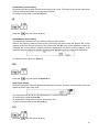
Squelch knob and AF Gain knob
SQUELCH KNOB
Turn this knob clockwise until background noise disappears.
AF GAIN KNOB
Turn clockwise to increase audio (speaker) output level and turn
counterclockwise to decrease audio (speaker) output level.
18
Sub Dial Keys
MKR
Pressing this key will illuminate a red lamp above the MKR switch.
When the AR-ALPHA is in the VFO mode or Memory mode and the LCD is displaying frequency
spectrum, the frequency marker cursor on the LCD screen can be moved by rotating the sub dial
knob (small knob to the left of this key).
While the MKR lamp is illuminated, pressing this key again will make the red lamp flash and
increase the cursor speed 10 times faster than normal. Press this key again to return to the normal
rate.
When the video screen is displayed, this function is disabled.
While in the Search mode, Memory Scan mode, and Select Scan mode, the sub dial knob is used
to select the respective bank.
DEF
Pressing this key will illuminate a green lamp above the DEF switch.
When the AR-ALPHA is in the VFO mode, rotating the sub dial will change the receive frequency by
the preset frequency step. To change the frequency step, while the green lamp is lit, press this key
again. The sub dial frequency step setup screen will appear.
Using the numeric keypad, enter the desired frequency step followed by kHz key.
To cancel the entry, press this key again.
When the video screen is displayed, this function is disabled.
While in the Search mode, Memory Scan mode, and Select Scan mode, the sub dial knob is used
to select the respective bank.
19
MAIN
Pressing this key illuminates an orange lamp above the MAIN switch.
When the AR-ALPHA is in the VFO mode, the function of the sub dial is the same as the main dial.
While the MAIN lamp is illuminated, press this switch again until the orange lamp flashes; this
enables the sub dial to change the receive frequency 10 times faster than the main dial.
Press this key again to return to the normal tuning speed.
While in the Search Mode, Memory Scan mode, and Select Scan mode, the sub dial knob is used
to select the respective bank.
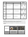
Lit
Rotate the sub dial to move the marker display line.
Press and hold this key until the MKR-LED flashes.
Flash This enables the marker to move 10 times faster than its
normal speed.
Lit
The frequency step changes with the designated steps.
Press and hold this key; a small window will appear on the
Flash LCD screen. This enables setting the frequency step using
the sub dial.
Lit
The sub dial operates the same as the main dial.
Press and hold this key until the MAIN-LED flashes.
Flash Rotating the sub dial changes the receive frequency at
10 times the rate of the main dial.
Dial Knobs
SUB DIAL (Small knob)
The sub dial knob is used to change the parameters of various settings or
to change the memory bank.
MAIN DIAL (Large Knob)
In the VFO mode, rotating this knob will change the receive frequency.
In the Memory Mode, rotating this knob will change the memory channel.
(To change the memory bank, rotate the sub dial knob.)
In the Search mode, the Memory Scan mode, and the Select Scan mode,
this knob is used to change the search/scan direction.
Soft Keys
There are seven (7) keys at the right of the LCD display; they are called “Soft Keys.”
The bottom key is designated as the DISPLAY KEY. Unlike the other 6 soft keys, the display key is
mostly used to control the functions of the LCD screen.
20
The functions of the soft keys vary according to the function displayed on the LCD screen.
The soft keys may also be used for user-defined functions depending on the displayed contents.
Display example of Page 1 and Page 2 in VFO mode
User defined key 1
User defined key 6
User defined key 2
User defined key 7
User defined key 3
User defined key 8
User defined key 4
User defined key 9
User defined key 5
User defined key 10
User defined key
Page 1
User defined key
Page 2
Display VFO list
Display VFO list
Below are the functions of the soft keys. When no description of a key is shown, there is no
assigned function for the soft key in that mode.
When a soft key function is displayed in a dark blue color, it is not selectable.
Normal SRCH
FFT
S.FR S.MOD ATT/ANT S.SCAN RBW
OPE
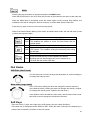
S-METER & STATUS INDICATORS
S-METER
The analog S-meter indicates the relative level of antenna input signal.
BUSY
Lit when the squelch is open.
21
AUTO
Lit when the AR-ALPHA is in automatic reception mode (AM, WFM, etc…).
REMOTE
Lit when the AR-ALPHA is controlled by a PC through the REMOTE 1 or REMOTE 2 connectors.
While the REMOTE indicator is lit, all functions (except AF GAIN and SQUELCH CONTROL) are
disabled
I/Q
Lit while I/Q signal is being sent through the USB port.
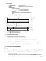
ACC1
This connector is used for an external device including the optional CR5000 recording cable.
1
12V DC output
(30mA maximum)
5
2
Detector output
6
3
Audio input
7
4
Control 1 (for CR5000)
8
Control 2 (for CR5000)
Audio output (High level)
(330mV r.m.s. at 600Ω)
Audio output (Low level)
(2.5mV r.m.s. at 600Ω)
Ground (or earth)
HEADPHONES
Use a 1/4 inch stereo type plug. When a headphone is connected, the internal speaker is
disabled.
1
Ground
2 Audio output (Right)
3 Audio output (Left)
Secondary functions of numeric keys
22
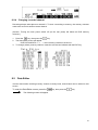
(1)
Press the
key, then press the 1 key.
Selecting the attenuation level
A soft key menu will appear at the right side of the LCD.
On this screen menu, choose one of the following five (5) selections.
1. RF AMP: ON, Attenuator: 0 dB
2. RF AMP: OFF, Attenuator: 0 dB
3. RF AMP: OFF, Attenuator: 10 dB
4. RF AMP: OFF, Attenuator: 20 dB
5. AUTO setting
Press the desired soft key to choose the desired setting.
When AUTO is selected, the ATT character on the LCD will be displayed in yellow.
Selecting antenna input port
Press the
key, then press and hold the 1 key for 2 seconds
A soft key menu will appear at the right side of the LCD.
On this screen menu, choose one of the following four (4) selections.
1. ANTENNA 1 2. ANTENNA 2 3. ANTENNA 3 4. ANTENNA 4
An optional AS5000 antenna relay switch is required to use more than 2 antenna inputs.
23
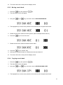
(2)
Press the
key, then press the 2 key.
Selecting the squelch mode
Performing the above steps will toggle between the Level Squelch Mode and Voice Squelch
Mode.
The VSQ icon appears at the top left on the LCD while in the Voice Squelch Mode.
In the Level Squelch Mode, the squelch level is adjusted by rotating the squelch knob.
Turning fully counterclockwise will disable the squelch function. Normally, turn the squelch knob
clockwise until background noise disappears.
In the Voice Squelch Mode, the AR-ALPHA automatically analyzes demodulated voice signals and
opens the squelch only when it detects human voice. Voice Level Squelch is available in the VFO
mode, Search Bank mode, and Memory Channel mode.
The BUSY indicator located below the S-meter will light while the squelch is open.
(3)
Press the
key, then press the 3 key.
24
Search Frequency Pass
When the AR-ALPHA receives a signal and stops searching In Search Receive Mode, performing
the above steps will register the frequency as a “pass” frequency and resume searching. The
AR-ALPHA will not stop at a pass frequency during future search cycles.
Up to 50 pass frequencies can be registered on each search bank.
The registered search frequencies can be viewed or deleted during search operations on the LCD
screen.
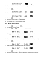
(4)
Press the
key, then press the 4 key.
Priority Function
After the priority channel is set, performing the above step will start priority receive.
The PRIO icon appears at the top left of the LCD while the priority function is activated.
Priority Channel Setting
Press the
key, then press and hold the 4 key for 2 seconds.
By performing the above steps, the priority setting screen will appear on the LCD.
1.
2.
3.
4.
Rotate the sub dial to select or set the desired priority channel.
Press the down arrow key to move the cursor downward.
Rotate the sub dial to set the priority time interval between 1 ~ 99 seconds.
Press the MHz key to confirm entry.
(5)
Press the
key, then press the 5 key.
Frequency Offset Function
After the offset frequency is set, performing the above step will activate the frequency offset
25
function. Repeating the above steps will toggle this function. While the frequency offset function is
activated, the DUP (Duplex) icon will appear at the top left of the LCD screen.
To disable this function, perform the above steps, then set the offset channel to “+00” and press the
MHz key.
A total of 48 offset channels are available and 01 ~ 20 channels out of 48 are user programmable.
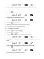
(6)
Press the
key, then press the 6 key.
Data Edit Function
Performing the above steps will display the data editor screen. In this mode, Memory bank and
search bank memory channel data can be edited on the LCD screen.
To exit this function, press the MHz key.
(7)
Press the
key, then press the 7 key.
Configuration Setting
The receiver’s configuration can be set on this screen.
To exit this function, press the MHz key.
(8)
Press the
key, then press the 8 key.
26
Select Memory Scan Setting
Performing the above steps will activate the select scan mode. The select scan function scans each
memory channel regardless of memory bank selection.
To exit from this function, press the VFO key.
(9)
Press the
key, then press the 9 key.
Select Memory Scan Setting
This function is available only in the memory channel receive mode.
While in the memory channel receive mode, performing the above steps will transfer the current
memory channel to the select memory. At the same time the SEL icon will be displayed on the LCD
indicating the current memory channel has been registered to the select memory channel. If the
registered memory channel is already registered, then the select memory channel will be deleted.
To exit this function, press the VFO key.
(10)
Press the
key, then press the decimal key.
Sleep Timer Setting
Performing the above steps will activate the sleep timer function. The time counter and the clock icon
appear at the top right of the LCD.
The sleep timer can be set for up to 99 minutes in 1 minute increments.
To set the timer, rotate the sub dial.
To deactivate the sleep timer function, set the timer to 0.
To exit from this function, press the CLR key.
(11)
Press the
key, then press the 0 key
27
IF Bandwidth Setting
Performing the above steps will display the IF Bandwidth setting screen on the LCD.
There are 10 bandwidth parameters and the selectable parameters are displayed in white.
Rotate the sub dial knob, then press the MHz key to confirm entry.
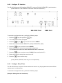
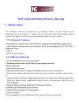
Rear Panel
1. ANT 1 Connector
N type connector. Antenna impedance is 50Ω nominal. An optional AS5000 antenna relay switch can
be connected to this connector.
2. ANT 2 Connector
SO-239 type connector. Antenna impedance is 50Ω nominal.
3. 10 MHz Input Connector
External 10 MHz reference signal input connector (BNC)
28
4. Ground (or Earth) Terminal
5. ACC 2 Connector
12V DC output (50mA
5
max.)
10V DC output (50mA
2
6
max.)
3 AGC 4.5V ~ 3.0V
7
4 No connection
8
An optional AS5000 antenna relay switch may be connected here.
1
Antenna switch
A
Antenna switch
B
No connection
Ground
6. EXT (External) Speaker Jack
3.5 mm mono jack for an external speaker (impedance 8Ω). When an external speaker is connected,
the internal speaker will be disabled.
7. MUTE Jack
Connecting the center pin to ground will mute the receiver.
8. AF OUT Jack
Line output for stereo audio. An external amplifier can be connected to these RCA type jacks.
29
9. I/Q OUTPUT Connector
USB 2.0 compatible I/Q data output of 300 kHz or 1 MHz selectable bandwidth. You
need to install the AOR IQ driver provided on the CD, or download it at www.aorja.com.
10. Remote 2 Interface Connector
The REMOTE RS-232C connector is designed for connection directly to the RS-232C serial port of a
PC. No interface is required, a standard RS-232C straight cable is all that is necessary. Connections
for a PC are as follows:
AR-ALPHA
DB-9 RS-232C cable
Pin # 2
Pin # 2
Pin # 3
Pin # 3
Pin # 5
Pin # 5 (Ground)
Pin # 7
Pin # 7
Pin # 8
Pin # 8
30
11. USB Connector
The USB connector is designed for connection directly to the USB port of a PC.
The RS-232C serial port and the USB port cannot be used at the same time.
Use either the USB driver program provided on the CD, or downloaded from the following URL.
http://www.ftdichip.com/ftdrivers.htm
Click “VCP Drivers”, then select the device number “FT232B”.
12. Power Input Connector
Using the supplied DC power cable, apply regulated 13.8V DC (min 2.2A) power to the AR-ALPHA.
The polarity is clearly marked. Avoid reverse polarity.
13. Main Power Switch
Main power switch. This switch must be always turned on for normal use.
2 Getting started
2-1 Preparing the AR-ALPHA for operation
2-1-1 Connect the antenna
For reception, connect the antenna to either Antenna 1 or Antenna 2 on the rear panel of the
AR-ALPHA. Usually, for signal reception below approximately 1 GHz, connect the antenna to the
Antenna 2 connector (SO-239 type connector).
Check the OPTIONAL ACCESSORIES chapter regarding the most suitable antennas according to
the frequency range you intend to receive.
31
2-1-2 Connect power
Connect power to the DC power jack on the rear panel of the AR-ALPHA. Always use a regulated
DC power supply (12 ~ 14 V with 2.2A or higher). Do not connect to a 24 V power supply.
2-2 Switching On for the first time
Set the squelch control to the ‘mid point’.
Turn on the main power switch on the rear panel of the AR-ALPHA.
Press the power switch at the top right of the front panel. Allow a couple of seconds for initializing,
then the S-meter will light. Then rotate the AF GAIN (volume) control knob to the ‘mid point’.
Please be careful - DO NOT switch on the AR-ALPHA while wearing headphones connected to the
receiver; there may be an audible click when the unit is switched on, or the volume may be
32
accidentally set too high.
The AR-ALPHA will take approximately 4 ~ 5 seconds before information appears on the LCD. This
is normal, as the microprocessor of the AR-ALPHA must complete an initializing process at the
beginning of a power-on cycle.
2-3 Squelch Circuit
In normal use, LEVEL SQUELCH is used. However, VOICE SQUELCH can be selected for search
and scan operations. The LEVEL SQUELCH parameter sets the AR-ALPHA to check the signal
strength of active frequencies and to only stop when the signal strength is above a preset level
(which is programmable).
To select LEVEL SQUELCH, rotate the squelch knob clockwise until background noise disappears.
The squelch will open only when input signal strength is above this set level.
To select VOICE SQUELCH, Press the
, then press the 2 key. The VSQ icon will appear at the
top left of the LCD screen.
Rotate the squelch knob until background noise disappears. The Squelch will open only when the
received voice audio level is above this set level. To return to LEVEL SQUELCH, repeat above
steps.
2-4 VFO selection
The AR-ALPHA has five (5) VFOs being identified as “VFO-A” through “VFO-E” at the top left of the
LCD. The term VFO stands for ‘Variable Frequency Oscillator’ and in modern receivers refers to
stored tuneable data that contains frequency, step, step-adjust, attenuator etc. Each time VFO key is
pressed, one of the five available VFOs (A~E) is selected.
The AR-ALPHA has an AUTOMODE setting, which in most cases automatically selects the proper
receive mode, and frequency step.
33
●
●
Direct VFO select
To select
, press the
key, then press the
key.
To select
, press the
key, then press the
key.
To select
, press the
key, then press the
key.
To select
, press the
key, then press the
key.
To select
, press the
key, then press the
key.
Select from the VFO LIST
Press the
soft key.
The VFO LIST screen will appear.
Using
Press the
key or
key, select the desired VFO.
soft key to confirm entry.
2-4-1 Tuning frequency
2-4-1-1 Entering a frequency using the numeric keypad
While in the VFO mode, enter the desired frequency followed by the MHz key or kHz key.
34
Example of frequency entry for 162.55 MHz
Press the [1] key, [6] key, [2] key, [.] key, [5] key, and [5] key.
Press the [MHz] key.
Example of frequency entry for 954 kHz (0.954 MHz)
Press the [9] key, [5] key, and [4] key.
Press the [kHz] key.
Editing frequency input
If there is an error during frequency input, press the CLR key. The frequency cursor will move
backward and delete the last digit entry. Re-enter the correct number from the numeric keypad.
Aborting frequency input
If for some reason you do not wish to complete frequency input, press the
key, then press the
CLR key.
2-4-1-2 Changing frequency using the main tuning dial
While in the VFO mode, a VFO frequency may be selected by using the main tuning dial, located at
the right side of the front panel. You may rotate the dial ‘clockwise’ to increase frequency or turn
‘counterclockwise’ to decrease frequency.
2-4-1-3 Changing frequency using UP arrow key or DOWN arrow key
The UP arrow key and DOWN arrow key provide a convenient method of changing frequencies.
The speed at which the receiver steps up or down depends upon the STEP SIZE, which defaults to
AUTO. In AUTO the step size, receiver mode etc. is taken from the factory pre-programmed band
plan but it may be overridden at any time.
35
Press the UP arrow key to tune the receiver upward in whichever step size is selected, use the
DOWN arrow key to tune the receiver frequency lower.
2-5 Changing receive mode
Due to the necessities of signal bandwidth, channel occupancy and transmission efficiency, different
receive modes are used by various radio services. Specifications for tuning step and receive mode
are allocated by government agencies but they are not consistent throughout the world. For this
reason, it may be necessary to change receive modes in order to monitor various transmissions.
For your convenience, receive mode and tuning step size have been pre-programmed into the
AR-ALPHA auto-mode band plan at the factory to simplify operation of the receiver. If needed, the
defaults may be manually overwritten at anytime so that you may select an alternative receive mode
and tuning step on any frequency.
AM
Amplitude Modulation – Used by broadcast services throughout the world on long wave, medium
wave and shortwave. AM is also used on the VHF airband, UHF military airband, and by some PMR
(Private Mobile Radio) and utility services.
FM
There are two common types of FM (Frequency Modulation), these are:
NFM – Narrow Band Frequency Modulation – this provides high quality communication for relatively
short distance operations. FM uses a wider frequency bandwidth than other modes such as
SSM so it is less efficient.
NFM is the most common mode used above 30 MHz with the exception of the airbands.
NFM is widely used on the VHF bands: VHF marine band, 2m and 70 cm amateur bands, by PMR
(Private Mobile Radio) and utilities. In the absence of a signal, the background noise may seem
quite loud. For ease in listening, the squelch knob should be rotated clockwise until he background
noise just disappears; this should be carried out while no signal is present. The point where the
background noise is cancelled is known as threshold point. Do not advance the squelch control
more than necessary or the receiver will appear to be desensitized and weaker signals will be
missed.
WFM – Wide Band Frequency Modulation – used by VHF and UHF broadcast stations.
Excellent audio quality is apparent due to the relatively wide frequency bandwidth of the
signal. Used only for local services such as VHF band stereo and UHF TV sound channels.
LSB – Lower Side Band – is a form of SSB (Single Side Band). LSB tends not to be used
commercially but is extensively used by Radio Amateurs on frequencies below 10 MHz.
36
This assists the separation of Commercial and Amateur users on traditionally shared bands.
SSB is a very efficient method of transmission as the unwanted second sideband and carrier are not
present. This allows the full transmitter power to be used to convey information within the wanted
sideband. As a result, long distance communications are possible on SSB in a narrower bandwidth
than required for most other modes.
USB – Upper Side Band – The same comments apply as for LSB. By convention, Radio Amateurs
use USB above 10 MHz.
CW -
Continuous Wave – Often referred to as Carrier Wave or Morse Code. Commonly used on the
short wave bands by radio amateurs toward the lower end of each band allocation. Some
commercial use of CW continues but much has been replaced by satellite and automated
communications.
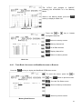
2-5-1 Auto-mode selection
When auto-mode is in use, receive mode and tuning step size are automatically selected by the
AR-ALPHA microprocessor.
To activate auto-mode or reconfirm its selection while in the VFO mode, press the MODE key.
The Mode Select screen will appear on the LCD.
Note: The Auto-mode is cancelled as soon as the receive mode, tuning step or other related data is
changed. Remember that auto-STEP and auto-MODE are linked, reselect the AUTO-MODE
if either have been adjusted and you require the auto band plan selection.
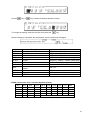
2-5-2 Receive mode selection
The AR-ALPHA has two (2) different mode settings, Simple Select Mode Setting and Advanced
Select Mode setting.
Simple Select Mode Setting
37
Advanced Select Mode Setting
In the Simple Select Mode Setting, a proper IF bandwidth is automatically selected with respect to
the receive mode.
In the Advanced Select Mode Setting, the receive mode and the IF bandwidth can be selected
independently.
To switch the Select Mode setting, press the MODE key while the MODE select screen is displayed.
Any receive mode may be selected at any frequency within the receiver’s frequency coverage range.
Press and hold the MODE key for 2 seconds to enter the AUTO-Mode.
In the Simple Select Mode Setting, the following modes are available:
WFM1, WFM2, FMST, NFM, SFM, WAM, AM, NAM, SAM, SAL, SAH, USB, LSB, CW1, CW2, ISB,
SBD, RZ-S, AIQ, and AUTO.
To make a selection, rotate the sub dial. To accept a selection, press the MHz key.
Description
WFM
WFM2
NFM
SFM
WAM
AM
NAM
SAM
SAL
SAH
USB
LSB
CW1
CW2
ISB
SBD
FMST
RZ-S
AIQ
AUTO
Mode
FM
FM
FM
FM
AM
AM
AM
AM
AM
AM
SSB
SSB
CW
CW
ISB
AM
FM
RZ-SSB
AIQ
AUTO
IF Bandwidth (kHz)
100
200
15
6
15
6
3
6
6
6
3
3
0.5
0.2
6
6
200
3
12+/-5
Remarks
Wide FM
Wide FM
Narrow FM
Super Narrow FM
Wide AM
Normal AM
Super Narrow AM
Synchronous AM
Synchronous AM (lower sideband)
Synchronous AM (upper sideband)
Single Sideband (upper sideband)
Single Sideband (lower sideband)
CW
CW
Independent Sideband
AM Sideband Diversity
FM Stereo
Real Zero Single Sideband
Analog IQ for DRM
Auto mode
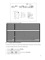
In the Advanced Select Mode setting, the following modes are available:
FM, FMST, AM, SAM, SAL, SAH, USB, LSB, CW, ISB, SBD, RZ-S, AIQ, and AUTO.
To make a selection, rotate the sub dial. To accept the selection, press the MHz key.
38
Description
FM
FMST
AM
SAM
SAL
SAH
USB
LSB
CW
ISB
SBD
RZ-S
AIQ
AUTO
Mode
FM
FM
AM
AM
AM
AM
SSB
SSB
CW
ISB
AM
RZ-SSB
AIQ
AUTO
Remarks
Normal FM
FM Stereo
Normal AM
Synchronous AM
Synchronous AM (lower sideband)
Synchronous AM (upper sdeband)
Single Sideband (upper sideband)
Single Sideband (lower sideband)
Normal CW
Independent Sideband
AM Sideband Diversity
Real Zero Single Sideband
Analog IQ for DRM
Auto mode
Selectable IF Bandwidth
Description
200
500
1K
3K
6K
15K
30K
100K
200K
300K
2-5-3
IF Bandwidth
200Hz
500Hz
1 kHz
3 kHz
6 kHz
15 kHz
30 kHz
100 kHz
200 kHz
300 kHz
Remarks
Available on CW mode only
Available on CW mode only
Available on WFM, FMST mode only
Available on WFM, FMST mode only
Available on WFM, FMST mode only
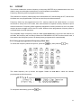
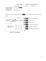
Additional decoding modes
Press the
key, then press the
key.
The D.Option setting sub menu screen will display on the screen.
39
Use the
key or
key to select the desired decoder function.
To change the setting, rotate the sub dial, then press the
key.
After the setting is completed, the confirmation screen (see below) will appear.
Items
NOTCH
NR
NB
SCR
IF-SFT
CW-Pitch
AGC
AFC
CTCSS
DCS
DTMF
Description
Auto Notch Filter Tone Eliminator
Noise Reduction
Noise Blanker
Analog voice descrambler
IF Shift
CW Pitch Control
Automatic Gain Control
Automatic Frequency
Control
Tone Squelch
Digital Code Squelch
DTMF Decoder
Parameters
OFF, LOW, MID, HIGH
OFF, LOW, MID, HIGH
OFF, LOW, MID, HIGH
OFF, 2000Hz~7000Hz (10Hz step)
0Hz(OFF),-1200Hz~1200Hz, (50Hz step)
300Hz~900Hz (50Hz step)
SLOW / MIDDLE / FAST
ON / OFF
OFF, ALL, 60.0Hz~254.1Hz (52 tones)
OFF, ALL, 017~754 (106 codes)
ON / OFF
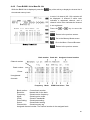
CTCSS (Continuous Tone Controlled Squelch System)
OFF
ALL
60.0
67.0
69.3
71.9
74.4
85.4
88.5
91.5
94.8
97.4 100.0 103.5
118.8 120.0 123.0
127.3 131.8 136.5 141.3
159.8 162.2 165.5
167.9 171.3 173.8 177.3
189.9 192.8 196.6
199.5 203.5 209.5 210.7
233.6 241.8 250.3
254.1
CTCSS tone frequencies (in Hz)
77.0
79.7
107.2 110.9
146.2 151.4
179.9 183.5
218.1 225.7
82.5
114.8
156.7
186.2
229.1
40
DCS (Digital Coded Squelch)
The DCS system uses 23 bit code data sent lower than the voice band frequency.
The data speed is 134.3 bit/sec in NRZ (Non-Return-Zero) format FM modulation.
OFF
047
114
152
225
263
332
413
464
565
703
ALL
050
115
155
226
265
343
423
465
606
712
017
051
116
156
243
266
346
431
466
512
723
023
053
122
162
244
271
351
432
503
624
731
025
026
054
065
125
131
165
172
245
246
274
306
356
364
445
446
506
516
627
631
732
734
DCS Codes
031
071
132
174
251
311
365
452
523
632
743
032
072
134
205
252
315
371
454
526
654
754
036
073
143
212
255
325
411
456
532
662
043
074
145
223
261
331
412
462
546
664
DTMF (Dual-Tone Multi-Frequency)
Low
(Hz)
2-6
High Frequency (Hz)
1209 1336
1447
669
1
2
3
770
4
5
6
852
7
8
9
941
*
0
#
DTMF frequency matrix
1633
A
B
C
D
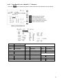
Changing tuning STEP size
The specification for channel occupancy, step (separation) and mode are regulated and allocated by
government agencies in accord with international agreements.
The allocation of frequency bands is not the same all over the world and channel separation (step)
varies from band to band. As an example, the channel separation (step) for the MW (medium wave)
band in the U.S.A. is 10 kHz while in Europe and Japan, it is 9 kHz.
For the above reasons, it is necessary to change the tuning step size according to local band plans.
The AR-ALPHA has been pre-programmed at the factory with most of the band plan data (selectable
between Japan, Europe and the USA) so that the AR-ALPHA will automatically select the
appropriate tuning step size and mode for the frequency chosen. This greatly simplifies operation of
the AR-ALPHA.
The factory pre-programming of step size can be manually overwritten so you may choose
alternative settings at will, or when band plans are updated.
To change the default tuning step size, press the STEP key. The frequency step will be highlighted at
the top right of the LCD (in reverse color), showing it is ready to accept a new parameter setting.
41
For your convenience, the following tuning step frequencies have been preprogrammed at the
factory:
1, 5, 10, 50, 100, 500Hz, 1, 2, 5, 6.25, 8.333, 9, 10, 12.5, 20, 25, 30, 50, 100, 500 kHz
Rotate the sub dial to select the desired receive step. To accept the displayed tuning step size,
press the MHz key.
The tuning step size may also be programmed in 1 Hz increments (via the keypad) so that unusual
step sizes other than those stated are possible. The acceptable step size range is between 1 Hz and
1 MHz in 1 Hz steps. Using the numeric keypad, enter the desired tuning step frequency in kHz.
Then press the MHz key to confirm entry.
2-7
IF Bandwidth
The IF bandwidth feature specifies how SELECTIVE the receiver will be when monitoring signals.
However, it is not simply a case of using the narrowest filter at all times. Particular modes require
sufficient amounts of bandwidth in order to operate, otherwise the received signal may not produce
intelligible sound.
The correct receive mode and IF bandwidth must always be selected for optimum reception. If the
bandwidth selection is too narrow, distortion or signal break-up may occur. If the bandwidth selection
is too wide, adjacent interference may be encountered.
For this reason, a selection of commonly used IF filter bandwidths are pre-programmed.
Typical examples of receive mode and IF bandwidth are:
300 kHz -- VHF FM broadcast
200 kHz -- VHF FM broadcast
100 kHz or 30 kHz – Wireless microphone, etc. (example: 30 KHz for satellite FAX)
15 kHz – PMR, amateur band, etc. FM 6 KHz may also be used
6 kHz – VHF/UHF airband, short wave broadcast, medium & long wave, PMR, etc.
3 kHz – Short wave amateur band SSB, short wave utility such as oceanic airband etc.
1 kHz, 500 Hz, 200 Hz – Morse code used by radio amateurs and some marine traffic on SW.
An appropriate IF filter is automatically selected in the AUTO MODE. However any combination of IF
filter and receive mode is possible in the manual mode. When you have manually selected an IF filter
bandwidth, AUTO MODE will be deactivated, but the receive mode, step size, etc will be retained
until they are changed manually.
42
2-7-1
Manually selecting IF bandwidth
Press the
key, then press the 0 (zero) key.
The IF Bandwidth (IFBW) select screen will appear on the LCD.
Select a new bandwidth from the list of 200, 500 Hz, 1, 3, 6, 15, 30, 100, 200, and 300 kHz by
rotating the sub dial key. The selectable IF bandwidth is displayed in white. Other parameters may be
selected (displayed in blue), however, they may not be suitable for the particular receive mode in
use.
To accept the new bandwidth selection, press the MHz key.
2-8
ATTENUATOR
Activating the attenuator reduces signal to the RF input stages of the AR-ALPHA to prevent
overloading in cases where the receiver is used in close proximity to strong transmissions.
The AR-ALPHA has five settings for ATT (attenuator), AMP ON 0 dB, AMP OFF 0 dB, 10 dB, 20 dB
and AUTO.
To change the ATT parameter setting, press the
key, then press the 1 key.
43
2-9
OFFSET
This function enables the receive frequency to be quickly SHIFTED by a predetermined value; this
makes it easy to track duplex-transmissions or check repeater inputs/outputs.
Frequency offset may also be programmed manually.
The locations for frequency offset storage are numbered 00 to 47 with 00 acting as OFF, and the first
20 offsets are user programmable. The rest are used for quick offset memories.
Frequency offset may be programmed into VFO, memory channel and search banks. It is most
convenient to set-up in the VFO mode, then save the data to a specific memory channel for quick
recall at a later time. Frequency offset is primarily designed for memory channel use, as it is a rather
complex process to toggle on/off in the VFO mode. However when programmed, frequency offset is
not detrimental to normal operations.
The acceptable range of frequency offset is 0 MHz to 999.999999 MHz. Of course if the offset is set
to 0 MHz, the frequency will not change. Before the FREQUENCY OFFSET function can be used, it
first needs to be configured (unless it is already factory programmed for certain bands).
2-9-1 Using pre-programmed frequency offset data
To access the frequency offset set-up menu, press the
key, then press the
key.
The Offset frequency set up screen will appear. Rotate the sub dial to select the desired
pre-programmed offset frequency.
To accept the offset setting, press the
key.
44
Below is a list of the pre-programmed offset frequencies.
Channel number
Offset frequency
20
100 kHz
21
4.0 MHz
22
4.6 MHz
23
5.0 MHz
24
8.0 MHz
25
9.0 MHz
26
10.0 MHz
27
15.0 MHz
28
16.0 MHz
29
16.5 MHz
30
18.0 MHz
31
18.45 MHz
32
20.0 MHz
33
24.1 MHz
34
37.4 MHz
35
47.2 MHz
36
48.0 MHz
37
55.0 MHz
38
126.35 MHz
39
130.0 MHz
=====================================================================
2-9-2
Entering new frequency offset data
Assume that you are in the VFO mode.
To access the frequency offset set-up menu, perform the following steps:
1. Press the
key, then press the
key.
2. The Offset frequency set up screen will appear on the LCD.
45
3. Rotate the sub dial to select the desired offset memory channel.
4. Using the numeric keypad, enter the desired offset frequency in MHz format.
(The shift direction can be changed by pressing the kHz key.)
(Example) For shift frequency 5 MHz, enter 5.00.
2-9-3 Activating frequency offset
To activate frequency offset, press the
key.
The DUP icon will display on the top of the screen to confirm operation.
2-9-4
Monitoring the offset frequency
To access the previously set offset frequency, press the
2-9-5
key.
Deactivating frequency offset
To deactivate the frequency offset function, select the +00 offset channel.
1.
Press the
key, press the
key.
2.
The frequency offset set up screen will appear on the LCD.
3. Rotate the sub dial to select channel +00.
4. Press the
key to confirm entry.
5. The DUP icon will disappear from the screen to confirm operation.
46
3.
Spectrum Display
Along with a high performance professional grade receiver, the AR-ALPHA has a built-in spectrum
display funtion that will show frequency activity over a specified bandwidth on the LCD.
3-1
3-1-1
LCD Display Screen (in VFO spectrum analyzer mode)
Operation mode display
FUNC
VSQ
PRIO
PASS
SEL
Function mode
Voice Squelch
Priority
Pass Memory
Select Memory
NOTCH
NR
NB
SCR
IF-SFT
CTCSS
Tone Squelch
AFC
DCS
DTMF
Digital Code Squelch
DTMF Decode
DUP
ADJ
OFFSET
RF-AMP
Duplex Mode
Frequency Adjust
Frequency Offset
Pre Amplifier
ANT:
ATT:
Auto Notch
Noise Reduction
Noise Blanker
Voice De-scramble
IF shift
Automatic Frequency
Control
Antenna Input
Attenuator
Timer
Key Lock
47
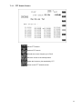
3-1-2
Basic Operation display
VFO mode (example)
MODE
IF-BW
STEP
VFO
VFO Mode
Frequency Receiving frequency
Sub
Operation analysis
operation
STEREO mode
Search mode (example)
MODE
IF-BW
STEP
Receive mode
IF bandwidth
Frequency step
Tag
Search bank tag
SRCH00
Search bank channel
Frequency Receiving frequency
Sub
Operation analysis
operation
VOICE mode
Cordless Telephone
Memory Scan mode (example)
MODE
IF-BW
Tag
Receive mode
IF Bandwidth
Frequency step
Receive mode
M00-00
Memory bank and memory
channel
IF bandwidth
Frequency Receiving frequency
Memory channel tag
NHK FM
WSP (Wide Span) mode (example)
(Note: No audio is available in WSP mode.)
STEP
Frequency step
WSP
WSP mode
Frequency Center frequency
48
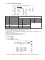
3-1-3
Spectrum Display (example)
(1)
(2)
▼
Marker:
(3)
RBW:
(4)
(5)
(6)
SPAN:
STEP:
OpMode:
Marker Position
Marker + Signal level
Resolution
Band
Width
Frequency Span
Frequency Step
Operation Mode
(7)
(8)
dB (upper)
dB (lower)
Reference level (H)
Reference level (L)
(9)
StartFreq.
Start Frequency
(10)
(11)
CenterFreq.
EndFreq.
Center Frequency
End Frequency
Note: The value of the Marker and the RBW will change according to the MKR operation.
The value of MAX.AVR or MED will be displayed next to RBW.
Marker MAX (example)
Peak AVR: 5 (example)
C-Peak MED: 4 (example)
49
Other display samples:
Waterfall Display
WSP Display
Search Band Browser
Search Tag Editor
Soft Keys
Below are the functions of the soft keys. When no description of a key is shown, there is no
assigned function for the soft key in that mode.
When a soft key is displayed in a dark blue color, it is not selectable.
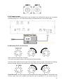
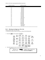
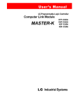
3-2
Display span setting
In the normal operation mode, the maximum display span is 10 MHz (+/- 5 MHz from the center
frequency.)
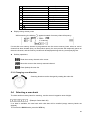
50
The chart at the left indicates the display span as 10 MHz and the display
step is 20 kHz (per pixel).
Since there are 500 pixels on the horizontal axis, the resolution of each pixel
indicates 20 kHz. (10 MHz / 500 = 20 kHz)
In the normal operation mode, the display span can be set between 250 kHz and10 MHz in
1 kHz increments. In this mode, the display step is calculated automatically.
The display step can be manually set between 500 Hz and 20 kHz in 10Hz increments. In this mode,
the display span is determined automatically.
In some cases, it is more convenient to set the display span by entering the start frequency and the
end frequency instead of setting the center frequency.
In this case, however, you need to remember that the actual display span will change according to
the start frequency or the end frequency.
51
3-2-1
Setting the display span
Press the
key.
The description of the soft keys, and their respective functions, will be changed.
→ Direct entry of the start frequency
→ Direct entry of the end frequency
→ Direct entry of the center frequency
→
→ Set the display span
→ Set the display step (per pixel)
When one of the soft keys is pressed, the related parameter
will be highlighted on the screen.
Enter a parameter by the numeric keypad.
Press the
key or
key to confirm entry.
(Example) Setting the display span to 5 MHz.
Press the
key, then press the
Press the
key, then press the
soft key.
key to confirm entry.
Display span is set to 5 MHz.
52
Setting the display span using the display frequency step (per pixel)
(Example) Set the display frequency step to 1 kHz per pixel.
Press the
key, then press the
Press the
key, then press the
soft key.
key.
Possible display span: 250 kHz ~ 10 MHz (in 1 kHz steps)
Display step range (per pixel): 500 Hz ~ 20 kHz (in 10 Hz step)
4.
Memory channels
Think of memory channels as pages in a notebook, each of which is numbered to identify it. Data
may be written to each new page (memory channel) and each page may be overwritten with new
data at any time. In other words, a memory channel can be used over and over again.
Each memory channel may hold:
One receive frequency
Receive mode
Tuning step
IF Bandwidth
Frequency step adjust
Voice squelch level
Antenna input setting
Attenuator / RF amplifier setting
Decoding mode
Offset frequency channel
Frequency pass channel
Select memory
Text comment of up to 12 characters
53
4-1
Memory Bank and Memory Channel
The AR-ALPHA features 2,000 memory channels and a priority channel.
There are 40 memory banks (groups) and each bank has 50 memory channels.
The alphanumeric comment may be used for easy identification of a specific memory channel at a
future time and to provide a “text search” function. The 2,000 memory channels are divided into 40
banks, each having 50 channels. The memory banks are identified by the first BANK number 0, 1, 2,
3, 4, 5, 6, 7, 8 and 9 and the individual channels are numbered from 00 to 39.
Examples are “00” for the first channel location in memory bank “0” and “39” for the last memory
channel in memory bank “0”.
“04-15” is the location: memory bank “04” channel “15”.
Memory bank Memory channel
The data contents of memory and search banks are held in an EEPROM; therefore no backup
battery is required for memory retention.
The stored data may be quickly and easily recalled, changed or deleted using the memory recall and
delete functions.
54
Memory channel browser (contents of memory channel)
Note: When the receiver is switched OFF, all VFO data will be automatically saved into
EEPROM memory storage.
4-2
Storing VFO frequencies and data into memory
The process to save a displayed VFO frequency to memory is as follows:
In the VFO mode, set the desired frequency, mode, attenuator, and so on.
(Example) Storing 80.000 MHz.
Press the
,
,
,
,
key from the
numeric keypad.
Press and hold the
key for 2 seconds.
The VFO browser screen will appear on the LCD.
Press the UP key to move the cursor to highlight the
MemCh (Memory channel) in reverse color, then enter
the desired memory bank and memory channel using
the numeric keypad followed by the
key.
55
(Example) Enter “0415” “MHz” will select memory bank 04 and memory channel 15.
Press the Down key to move the cursor to
highlight the Title in reverse color. To add a
text comment (optional), press the Title Edit
key of the soft key on the right side of the LCD.
Use the numeric keypad and soft keys for text
entry.
Press the
key to save the data to the
specified memory location.
4-3
Memory read “M.RD”
Once frequency and mode data has been stored into a memory location, its retrieval is quick and
simple.
From the VFO mode, press the
key. This changes the VFO mode screen into the memory
mode screen.
Rotate the main dial to select the desired memory channel.
If the memory bank and memory channel are already programmed, then enter the 2 digits of the
memory bank number followed by the 2 digits of the desired memory channel from the numeric
keypad.
(Example)
Enter
Read the memory bank 00, memory channel 02.
,
,
,
,
from the numeric key pad.
(Note) If a vacant memory content is recalled, then the memory bank 00, memory channel 00 will
be recalled.
To return to VFO mode screen, press the
key.
56
●
Soft key operation in memory receive mode
Functions of User 1 ~ User 5 and Page 1 are similar to the VFO mode except the
Soft Key.
→→→
.
In the VFO mode, pressing the
soft key will display the VFO list.
In the memory mode, it displays the BANK List.
4-4
Memory Mode
From VFO mode as on the left, to enter the
Memory Mode, press the
key.
VFO mode
57
The “VFO-A” icon changes to “M00-03”
indicating the AR-ALPHA is in the Memory
Mode.
While in the Memory Mode, press the
soft key to display the Bank List.
Memory mode
Press the
or
key to browse
through the bank list.
Return to memory screen
Memory channel set
Go to Bank browser
Display channel list
Return to memory screen
Bank List
4-4-1 From Bank List screen to MemBank screen or Browser
Press the
soft key to display the MemBank 00 Browser screen.
To move the cursor, press the
key.
or
Return to previous screen.
Go to the Title Editor screen.
Return to Memory mode screen.
Return to previous screen.
Memory Bank Browser
58
Bank number
Available free memory number
Memory name tag
Assigned memory
channel number
Write protect
While above screen is displayed, press the
key of the soft key to go into the Title Editor
screen.
Return to previous screen.
Confirm title entry.
Delete character.
Move the cursor rightward.
Move the cursor leftward.
Select the previous character.
Memory Title (Tag) Editor
59
4-4-2 From BANK List to MemCh List
While the BANK List is displayed, press the
key of the soft key to display the channel list of
the selected memory bank.
A total of 10 channel (00~09) contents will
be displayed. A channel in white color
indicates a registered channel, and a
channel in blue color indicates the channel
is not registered.
Press the
or
key to move the
cursor.
Return to the previous screen.
Go to the Memory Mode screen.
Go to the Mem. Channel Browser
Return to the previous screen.
Bank number Bank title Assigned channel number
Channel number
Bank number
Cursor
Unregistered
channels
Frequency
Mode
IFBW Pass Select
Title
Bank number: Current bank number
Bank title:
Named title for the bank
Frequency:
Stored receive frequency
Mode:
Stored receive mode
IFBW:
Stored IF bandwidth
Pass Setting:
Stored pass setting
Select:
Stored select setting
Channel title:
Stored memory tag
Assigned channel number: The channel number in the assigned bank
60
4-4-3 From MemCh List to MemCh **-** Browser
Press the
key to display the Memory Channel Brower of the selected memory channel.
Return to previous screen.
Go to Title Editor screen.
Go to Memory Mode screen.
Return to MemCh List screen.
Return to previous screen.
Memory Channel Browser
Title
Freq.
Mode
IFBW
Channel Tag
Receive frequency
Receive mode
IF bandwidth
ANT
ATT
AGC
StepAdj. Step adjust
AFC
Offset
Offset
VSQ
NOTCH
IF-SFT
IF shift
NR
CW Pitch CW pitch frequency NB
De-Emp. De-emphasis
SCR
Antenna select
Attenuator
AGC setting
AFC setting
Voice squelch setting
Notch filter
Noise reduction
Noise blanker
Voice Descrambler
CTCSS
DCS
DTMF
IF-Inv.
CTCSS setting
DCS setting
DTMF setting
IF inversion
F.Span
Frequency span
Select
Pass
Select setting
Pass setting
61
While the Memory Channel Browser screen is
displayed, press the
key to go to Title
Editor screen.
Return to the previous screen.
Confirm entry
Delete character
Move cursor rightward
Move cursor leftward
Select the previous character
Title (Tag) Editor
62
●
Soft key operation and functions
63
5.
SCAN – scanning memory channels
The AR-ALPHA has a SCAN mode whereby the contents stored in the MEMORY CHANNELS ARE
AUTOMATICALLY RECALLED AND MONITORED very quickly, that is, “scanned” for activity.
*** It is important that you do not confuse SCAN and SEARCH modes. ***
SEARCH mode (covered later in this manual) automatically TUNES THE RECEIVER THROUGH
ALL FREQUENCIES between two specified frequency limits, looking for active frequencies.
5-1
SCAN – outline introduction
During SCAN, the AR-ALPHA automatically recalls memory channels which contain data (in numeric
order) and monitors them looking for activity. When an ‘active’ memory channel is located (when a
signal is found and the squelch is open), the AR-ALPHA will temporarily stop scanning.
5-2
Starting SCAN
Before starting the scan process, some memory channels need to be pre-programmed with data.
Ensure that the squelch is set to the threshold point so that background noise is
cancelled and the squelch closes (otherwise the scan function will not operate).
In the VFO mode (as shown to the left), press the
key to go into the memory mode.
Rotate the main dial to select the desired memory
bank to scan.
Press the
VFO mode screen
key again.
(example)
When SCAN has been selected, only the currently
displayed memory bank WHICH CONTAINS DATA will
be scanned, receive mode and frequency are
unimportant. Any memory channels that contain no
data (empty) will be ignored (skipped).
Memory mode screen (example)
64
Scan mode (searching)
Scan mode (receiving)
5-3
Scan operation
①
①
①
①
①
①
①
①
①
65
Item
①
①
①
①
①
①
①
①
①
Operation
MODE:NFM
Receive mode
IFBW:15k
Receiver IF bandwidth
M01-22
Bank 01, Channel 22
399.462500 MHz
Memory channel frequency
MemCh01-22
Memory channel text
VOICE
Decoding mode: VOICE
DTMF: AAAA
DTMF decoded data
M01-00Mem Ch01-00 398.030M Scan List
Cursor
Current receive channel
Display during memory scan
While scanning, the blinking
appears instead of memory channel frequency.
scanning
If more than one memory channel is programmed into the current memory bank, when an ‘active’
channel has been located (busy, so the squelch opens), the scan process will temporarily pause on
the active channel, and the memory location will be displayed along with any accompanying text.
Soft key operations
Read the memory channel at the cursor.
Move the cursor to the recently scanned channel.
Clear (delete) the scan list.
5-3-1 Changing scan direction
Scanning direction can be changed by rotating the main dial.
5-4
Selecting a scan bank
To select another memory bank for scanning, use the numeric keypad to enter 4 digits.
(Example: Select bank 02)
If no data is available, the next bank with valid data will be recalled (empty memory banks are
skipped).
To exit from the SCAN mode, press the VFO key.
66
5-5
Bank Link
The AR-ALPHA has a built-in Bank Link function to allow scanning a single bank or a user-selected
group of memory banks.
5-5-1 Setting Bank Link
1. Press the
key, then press and hold the
key for 2 seconds.
2. The Scan Group screen will appear.
Group: 00
Delay: 2.0s
Free: OFF
Scan group number
Scan delay time
Scan free time
00, 01 ~ 19
0.1 ~ 9.9s (in 0.1 second steps)
OFF (00), 01~60 seconds
3.
Rotate the sub dial to select the desired item, then use the
4.
Validate with “Group Set” soft key or the MHz key.
Press the
5-6
or
key to change.
key if you prefer to cancel.
Select Scan
Select scan enables you to ‘tag’ memory channels to make a temporary list up to 50 channels in the
same memory bank for scanning in a separate list called the SELECT SCAN LIST.
5-6-1 Adding select scan channels in memory read
1. Press the
key to enter the memory mode.
2. Locate the memory channel to add select scan channel.
3. Press the
key, then press the
key.
4. The ‘SEL’ icon will appear on the LCD.
67
(Example)
Adding select scan channels can also be performed in the memory channel browser screen.
Memory channel browser
5-6-2
Start select scan
Press the
key, then press the
key.
68
Add the channel to the select memory.
Transfer the cursor data to the newest list.
Clear the displayed list.
5-7
Channel Pass
When scanning, you may encounter active memory channels which you do not wish to currently
monitor. It is possible to manually force the scan process to continue.
5-7-1 Setting channel pass
1. Press the
key to enter the memory mode.
2. Select the memory channel you wish to pass.
3. Press the
key, then press the
key.
4. The ‘PASS’ icon will appear on the LCD.
You can also do the same on the memory channel browser screen.
69
6.
6-1
6-1-1
Search
Search Setting
Setting
1. Press and hold the
key for 2 seconds.
2. The following screen will appear.
3. Press the
key.
4. The following screen will appear.
70
6-1-2
Search Bank Browser setting
Title
LoFreq.
HiFreq.
Mode
Step
IFBW
StepAdj.
Name Tag
Lower limit freq.
Upper limit freq.
Receive mode
Frequency step
IF bandwidth
Step adjust
IF-SFT
CW Pitch
De-Emp.
IFshift
CW pitch frequency
De-emphasis
ANT
ATT
AGC
AFC
VSQ
NOTCH
NR
NB
SCR
Antenna
Attenuator
AGC setting
AFC setting
Voice squelch
Notch filter
Noise reduction
Noise blanker
Voice Descrambler
CTCSS
DCS
DTMF
IF-Inv.
CTCSS setting
DCS setting
DTMF setting
IF inversion
To browse through the settings to be edited, press the up or down arrows.
The title can be edited by pushing the “Edit Title” soft key.
You can change the lower and upper limit frequencies by selecting these and simply enter a new
frequency with the ten keys.
The remaining values can be changed using the sub-dial.
Validate the changes with the “Bank Set” soft key.
6-1-3
Start search
1. Press the
key.
2. The following screen will appear.
To change the Search Bank, enter a 2-digit number (00~39) from the numeric keypad.
71
Go to PASS Freq. List.
The frequency selected by the cursor will be sent to the VFO (using VFO-D).
Move to the newest receive frequency.
Delete all search list.
● Transfer to VFO-D
Use the
Pressing the
key to select the desired frequency to transfer.
key will transfer the selected frequency to VFO-D.
Press the
to move the cursor to select desired frequency list key, then press the
key to transfer the VFO mode.
● Pass List
In the Search mode, press the
key to select the Frequency Pass List.
72
Return to the Search List screen.
Delete the frequency at the cursor in the PASS Freq. List.
Delete all PASS frequencies from the frequency list.
6-2
Search Group
The search function will tune continuously between two (2) selected frequencies in increments
of the currently designated frequency step. By using the Search group function, it automatically
searches frequencies across the pre-selected search groups.
6-2-1
Setting Search Group
Press the
key, then press and hold the
The following screen will appear.
key for 2 seconds.
To select a category, rotate the sub dial.
Group:00
A total of 19 (01~19) can be selected. To select the group, use the
key.
(Note: The 00 cannot be selected.)
Delay:2.0s
Duration before resuming search after a signal is received.
Selectable range: 0.0~9.9 (seconds)
To set the delay, use the
key.
Free:OFF
Duration of receiving.
Selectable range: OFF, 01~60 (seconds).
To set the duration, use the
key.
AutoStore:OFF Select auto store on/off.
This function will automatically store an active frequency into memory bank
39.
73
Link:
If memory channels on bank 39 are full, then a frequency will be overwritten.
Displays search bank of 00~39. To select the search bank, rotate the sub dial
and press the
key or press the
key to deselect.
Press the
soft key to start group search.
● Soft key operation and functions
Press the
Press and hold the
Press the
key, then press the
key.
key
key.
74
7.
FFT Search
The AR-ALPHA has a FFT (Fast Fourier Transform) search function that enables high speed
searches using search bank data.
Unlike the ordinary search function that searches between a low frequency and a high
frequency, the AR-ALPHA FFT search examines a 10 MHz block of band data. When more than
10 MHz of bandwidth needs to be searched, the AR-ALPHA will automatically continue the FFT
search process in 10 MHz increments.
7-1
FFT Search setting
1. Press the
key.
2. The following screen will appear.
Recall bank setting.
Set Search bank (selectable range: 00~39)
Recall FFT frequency step. Rotate the sub dial to select.
Recall threshold level of FFT search. Rotate the sub dial to
select.
Start FFT search.
75
7-1-1 FFT Search Screen
Pause FFT search.
Resume FFT search.
Transfer the cursor frequency to VFO-D.
Move the cursor to the latest position.
Delete the frequency list searched by FFT.
Return to the FFT search screen.
76
●
Soft key function operation and functions
Press the
key
77
8.
MISCELLANEOUS SETTINGS
8-1 Soft key registration
The functions of the soft keys vary with respect to each operation screen. By assigning variable
functions to each soft key, it is much easier to operate the AR-ALPHA.
Soft Key function
8-1-1
●
Soft key
Soft Key Operation
Yellow color
Function on the process to be assigned.
Clear blue color
Function assigned
Dark blue color
No function assigned
Switch between User1~
~User5 and User6~
~User10
Press the
key or
key.
78
8-1-2
Soft key registration
(Example)
1.
Assign the User1 key to set a V.SCR (Voice Descrambler) frequency of 2100Hz.
Press and hold the User1 soft key for 2 seconds.
The color of the User1 key will change from blue to yellow and 9 appears below the soft key.
This number represents the number of remaining steps which can be registered into each “user”
key.
In the meantime, the
Press the
key will change to the
key.
key.
The FUNC icon will appear.
The number below the soft key is changed from 9 to 8.
2. Press the
key.
The D.Option setting sub screen is displayed.
The number below the soft key is changed from 8 to 7.
3. Press the
key three (3) times.
The V.SCR changes in reverse color.
The number below the soft key is changed from 7 to 6.
4. Rotate the sub dial to select 2100Hz.
The SCR icon is displayed.
The number below the soft key is changed from 6 to 5.
5. Press the
key.
The D.Option setting sub screen will go off.
The number below the soft key is changed from 5 to 4.
6. Press and hold the User1 soft key for 2 seconds.
The color of User1 will change from yellow to blue.
This completes registration of the selected functions in the soft key.
As described above, using the assigned soft key will greatly simplify complex key operations.
8-2
Voice Recording
The AR-ALPHA has a built in DVR (Digital Voice Recorder).
Total recording time is 52 minutes (except in the WFM1/WFM2/FMST modes). There are five (5)
recording memory channels.
Notes:
FM stereo signals are recorded in mono.
In the ISB mode, both sideband signals are mixed and recorded.
In the CW mode, signals are recorded as mono.
79
Quality of playback sound may be degraded as compared with the original signals even if
recorded in the WFM mode or WAM mode.
The receive mode should not be changed during the recording process.
Never turn the main power switch off during recording, or loss of the recorded signal will result.
To play back the recorded signal properly, select the same receive mode as when signals were
recorded.
When DVR memory channels are all full, no further recording can be done.
8-2-1 Recording
1. Press the
key to start recording.
2. The DVR will capture data beginning 6 seconds prior to the record key being pressed.
3. A red bullet and a white recording progress indicator will appear on the LCD.
8-2-2
Stop recording
1. Press the
key while recording.
2. The red round icon will be changed to CUE.
8-2-3
Playback audio
1. Press the
key, then press the
key.
2. The color of the soft keys will change.
Clear blue --- Recorded (saved)
Dark blue --- Channel not used (empty)
(Example)
Channel 0
Channel 1
Channel 2
Channel 3
Channel 4
Channel 5
Grey
Blue
Blue
Blue
Blue
Blue
Recorded
Empty
Empty
Empty
Empty
Empty
3. Press the desired (recorded) channel soft key to play back audio.
(On the above example, the
key is available for playback.)
4. The CUE icon will change to a green triangle icon indicating playback has taken place.
5. To stop playback, press the
key.
80
8-2-4
Changing recorded channel
Recording always takes place on channel 0. To save a recording to memory, the memory contents
need to be moved to another vacant channel.
(Caution: Turning the main power switch off (on the rear panel) will delete all DVR memory
contents.)
1. Press the
key, then press the
key.
2. The data editor screen will appear.
CUE DATA MOVE 0 => 1 --- move memory contents to channel 1.
3. To change (select) memory channel, rotate the sub dial and validate with the ENT key.
8-3
Data Editor
Various data entries including memory channel, memory bank, search bank can be edited on this
screen.
To enter the Data Editor screen, press the
key, then press the
key.
The following screen will appear.
81
(MOVE / COPY)
MEM BANK MOVE
MEM BANK COPY
SRCH BANK MOVE
SRCH BANK COPY
MEM CH MOVE
MEM CH COPY
SCAN GR. MOVE
SCAN GR. COPY
SRCH GR. MOVE
SRCH GR. COPY
CUE DATA MOVE
(Delete)
MEM BANK DEL
SRCH BANK DEL
MEM CH DEL
MEM PASS CH ALL
SRCH PASS CH ALL
MEM BANK ALL
SRCH BANK ALL
CUE DATA DEL
CUE DATA ALL
8-3-1
Move / copy
Move memory bank
Copy memory bank
Move search bank
Copy search bank
Move memory channel
Copy memory channel
Move scan group
Copy scan group
Move search group
Copy search group
Move recorded audio
Delete
Delete memory bank
Delete search bank
Delete memory channel
Delete pass memory ch.
Delete search pass freq.
Delete all memory banks
Delete all search banks
Delete recorded audio
Delete all recorded audio
Move contents of memory bank.
Copy contents of memory bank.
Move contents of search bank.
Copy contents of search bank.
Move contents of memory channel.
Copy contents of memory channel.
Move contents of scan settings.
Copy contents of scan settings.
Move contents of search settings.
Copy contents of search settings.
Move recorded audio on channel 0.
Delete contents of memory bank.
Delete contents of search bank.
Delete contents of memory channel.
Delete all pass memory channels.
Delete all search pass frequencies.
Delete all memory banks.
Delete all search banks.
Delete recorded audio contents.
Delete all recorded audio channel contents.
Moving memory bank
1. Press the
key, then press the
key.
2. The data editor screen will appear.
3. Using the
key or
key, move the cursor to MEM BANK MOVE.
4. The highlighted (in reverse color) number on the left side is the original memory bank.
5. Rotate the sub dial to select the memory bank. (Above example shows bank 01).
82
6. Press the
key to move the cursor.
7. Rotate the sub dial to select the desired memory bank.
8. Press the
key to confirm entry.
9. At this point, the data on bank 01 is deleted and moved to bank 02.
10. The screen will return to the previous display screen.
(Note: If memory bank protection is set to ON, the memory contents will not be transferred.)
8-3-2
Copying memory bank
1. Press the
key, then press the
key.
2. The data editor screen will appear.
3. Using the
key or
key, move the cursor to MEM BANK COPY.
4. The highlighted (in reverse color) number on the left side is the original memory bank.
5. Rotate the sub dial to select the memory bank. (Above example shows bank 01).
6. Press the
key to move the cursor.
7. Rotate the sub dial to select the memory bank to be copied.
8. Press the
key to confirm entry.
9. At this point, the data of bank 01 is copied to bank 02.
83
10. The screen will return to the previous display screen.
8-3-3
Moving search bank
1. Press the
key, then press the
key.
2. The data editor screen will appear.
3. Using the
key or
key, move the cursor to SRCH BANK MOVE.
4. The highlighted (in reverse color) number on the left side is the original search bank.
5. Rotate the sub dial to select the memory bank. (Above example shows bank 01).
6. Press the
key to move the cursor.
7. Rotate the sub dial to select the desired search bank.
8. Press the
key to confirm entry.
9. At this point, the data of bank 01 is deleted and moved to bank 02.
10. The screen will return to the previous display screen.
8-3-4
Copying search bank
1. Press the
key, then press the
key.
2. The data editor screen will appear.
3. Using the
key or
key, move the cursor to SEARCH BANK COPY.
4. The highlighted (in reverse color) number on the left side is the original search bank.
84
5. Rotate the sub dial to select the search bank. (Above example shows bank 01).
6. Press the
key to move the cursor.
7. Rotate the sub dial to select the memory bank to be copied.
8. Press the
key to confirm entry.
9. At this point, the data of bank 01 is copied to bank 02.
10. The screen will return to the previous display screen.
8-3-5
Moving memory channel
1. Press the
key, then press the
key.
2. The data editor screen will appear.
3. Using the
key or
key, move the cursor to MEM CH MOVE.
4. The highlighted (in reverse color) number on the left side is the original memory bank.
5. Rotate the sub dial to select the memory bank. (Above example shows bank 00, channel 04).
6. Press the
key to move the cursor.
7. Rotate the sub dial to select the desired memory bank and channel.
8. Press the
key to confirm entry.
9. At this point, the data of bank 00, channel 04 is deleted and moved to bank 01, channel 00.
85
10. The screen will return to the previous display screen.
8-3-6
Copying memory channel
1. Press the
key, then press the
key.
2. The data editor screen will appear.
3. Using the
key or
key, move the cursor to MEM CH COPY.
4. The highlighted (in reverse color) number on the left side is the original memory bank and
channel.
5. Rotate the sub dial to select the search bank. (Above example shows bank 00, channel 04).
6. Press the
key to move the cursor.
7. Rotate the sub dial to select the memory bank and channel to be copied.
8. Press the
key to confirm entry.
9. At this point, the data of bank 00 channel 04 is copied to bank 01, channel 00.
10. The screen will return to the previous display screen.
8-3-7
Moving scan group data
1. Press the
key, then press the
key.
2. The data editor screen will appear.
3. Using the
key or
key, move the cursor to SCAN GR. MOVE.
4. The highlighted (in reverse color) number on the left side is the original scan bank group (00).
86
5. Rotate the sub dial to select the scan bank group. (Above example shows bank 01).
6. Press the
key to move the cursor.
7. Rotate the sub dial to select the desired scan bank.
8. Press the
key to confirm entry.
9. At this point, the data of bank 01 is deleted and moved to bank 02.
10. The screen will return to the previous display screen.
8-3-8
Copying scan group data
1. Press the
key, then press the
key.
2. The data editor screen will appear.
3. Using the
key or
key, move the cursor to SCAN GR. COPY.
4. The highlighted (in reverse color) number on the left side is the original memory bank and
channel.
5. Rotate the sub dial to select the search bank. (Above example shows bank 02).
6. Press the
key to move the cursor.
7. Rotate the sub dial to select the desired scan bank.
87
8. Press the
key to confirm entry.
9. At this point, the data of bank 02 is copied to bank 03.
10. The screen will return to the previous display screen.
8-3-9
Moving search group data
1. Press the
key, then press the
key.
2. The data editor screen will appear.
3. Using the
key or
key, move the cursor to SRCH GR. MOVE.
4. The highlighted (in reverse color) number on the left side is the original scan bank group (00).
5. Rotate the sub dial to select the scan bank group. (Above example shows bank 01).
6. Press the
key to move the cursor.
7. Rotate the sub dial to select the desired scan bank.
8. Press the
key to confirm entry.
9. At this point, the data of bank 01is deleted and moved to bank 02.
10. The screen will return to the previous display screen.
8-3-10
Copying search group
1. Press the
key, then press the
key.
2. The data editor screen will appear.
3. Using the
key or
key, move the cursor to SRCH GR. COPY
88
4. The highlighted (in reverse color) number on the left side is the original memory bank and
channel.
5. Rotate the sub dial to select the search bank. (Above example shows bank 02).
6. Press the
key to move the cursor.
7. Rotate the sub dial to select the desired scan bank.
8. Press the
key to confirm entry.
9. At this point, the data of bank 02 is copied to bank 03.
10. The screen will return to the previous display screen.
8-3-11
Moving recorded voice data
1. Press the
key, then press the
key.
2. The data editor screen will appear.
3. Using the
key or
key, move the cursor to QUE DATA MOVE.
4. Voice data is always recorded on CUE channel 0. In order to save voice data, it must be copied
onto CUE1~CUE5.
5. Rotate the sub dial to select the new voice memory channel. (Above example shows channel
02).
6. Press the
key to move the cursor.
7. The screen will return to the previous display screen.
8-3-12
Deleting memory bank
89
1. Press the
key, then press the
key.
2. The data editor screen will appear.
3. Using the
key or
key, move the cursor to MEM BANK DEL.
4. Rotate the sub dial to select the desired memory bank to delete.
5. Press the
key to delete the memory bank.
(Note: In order to delete the memory bank, write protection of the memory bank must be set to OFF).
8-3-13
Deleting search bank
1. Press the
key, then press the
key.
2. The data editor screen will appear.
3. Using the
key or
key, move the cursor to SRCH BANK DEL.
4. Rotate the sub dial to select the search bank to be deleted.
5. Press the
8-3-14
key to delete.
Deleting memory channel
1. Press the
key, then press the
key.
2. The data editor screen will appear.
90
3. Using the
key or
key, move the cursor to MEM CH DEL.
4. Rotate the sub dial to select the memory channel to be deleted.
5. Press the
8-3-15
key to delete.
Deleting memory pass channel
1. Press the
key, then press the
key.
2. The data editor screen will appear.
3. Using the
key or
key, move the cursor to MEM PASS CH ALL.
4. Rotate the sub dial to select the memory bank for the memory pass channels.
5. Press the
8-3-16
key to delete all memory pass channels.
Deleting all search pass channels
1. Press the
key, then press the
key.
2. The data editor screen will appear.
3. Using the
key or
key, move the cursor to SRCH PASS CH ALL.
4. Rotate the sub dial to select the search bank for the search pass channels.
5. Press the
8-3-17
key to delete.
Deleting all memory banks
1. Press the
key, then press the
key.
2. The data editor screen will appear.
3. Using the
key or
4. Press the
key to delete all memory banks.
8-3-18
key, move the cursor to MEM BANK ALL.
Deleting all search banks
1. Press the
key, then press the
key.
91
2. The data editor screen will appear.
3. Using the
key or
4. Press the
key to delete all search banks.
8-3-19
key, move the cursor to SRCH BANK ALL.
Deleting voice record channel
1. Press the
key, then press the
key.
2. The data editor screen will appear.
3. Using the
key or
key, move the cursor to CUE DATA DEL.
4. Rotate the sub dial to select the voice record channel.
5. Press the
8-3-20
key to delete.
Deleting all recorded voice data
1. Press the
key, then press the
key.
2. The data editor screen will appear.
3. Using the
5.
Press the
8-4
key or
key, move the cursor to CUE DATA ALL.
key to delete all recorded voice data.
Configuration settings
The configuration menu is used to set fundamental operating parameters and other variables which
do not appear in any menu heading.
1. Press the
key, then press the
key.
2. The configuration screen will appear.
92
The description of each menu is as follows:
BackLight
Backlight On/Off of the display
BEEP
Beep On/Off
RF-GAIN
RF gain setting
10 MHz
Reference oscillator input select
TV-Format
Video format select
I/Q BW
I/Q output bandwidth setting
VSQ-LV
VSQ-DL
SERIAL
SPEED
FLOW
Voice squelch level setting
Voice squelch delay setting
Serial port select
Serial port baud rate setting
Serial port flow control setting
Main board
Panel board
Decoder board
RF-Unit
Firmware version of the main (control) board (user upgradeable)
Firmware version of the control panel (user upgradeable)
Firmware version of the decoder board (user upgradeable)
Firmware version of the RF Unit (hard coded to chip)
8-4-1
Configure backlit illumination
The AR-ALPHA is equipped with a high density backlight lamp to illuminate the LCD when operating.
To configure backlight illumination, perform the following steps:
1.
Press the
key, then press the
2.
The configuration screen will appear.
3.
Press the
4.
Rotate the sub dial to select on or off.
key or
key.
key to move the cursor to BackLight
93
5.
Press the
key to confirm entry.
When the back light of the display is set to off, the LCD screen is invisible and may be difficult to
operate.
If you wish to set the display on again, please perform the following procedures:
1. Press and hold the
2. Press the
3.
key to power off the unit. Wait about 10 seconds.
key, then press the
key.
Rotate the sub dial clockwise with one click. Press the
key.
(Note: The brightness of the LCD is not adjustable.)
8-4-2
Configure beep
The AR-ALPHA emits confirmation ‘beeps’ when the keypad is used. A ‘HIGH’ pitched beep indicates
correct operation while a ‘LOW’ pitched beep indicates that an error or unexpected entry has taken
place. The volume of the beep is independent of the main volume control. It is recommended that the
beep function be enabled, especially when a new user is becoming familiar with the AR-ALPHA.
To access the configuration menu, perform the following steps:
1. Press
key, then press the
key.
2. The configuration screen will appear.
3. Press the
key or
key to move the cursor to BEEP.
4. Rotate the sub dial to select on or off.
5. Press the
8-4-3
key to confirm entry.
Configure RF-GAIN (Radio Frequency Gain)
The RF gain setting switches the attenuator or preamplifier to suit the band conditions and antenna in
use. The value can be adjusted according to local receiving conditions.
To access the configuration menu, perform the following steps:
1. Press the
key, then press the “MODE” key.
2. The “D.Option settings” menu will appear.
3. Press the
key or
key to move the cursor to AGC.
4. Rotate the sub dial to set the AGC to OFF.
5.
Press the
key to confirm entry.
The SQUELCH dial now does control the RF-GAIN.
94
8-4-4
Configure reference signal input
This function enables you to select an external reference signal for the AR-ALPHA. The AR-ALPHA
has a stable built-in reference oscillator, however, an external high stability 10 MHz reference (such
as off-air, atomic coupled) can be accepted by the BNC connector, marked “10 MHz”, on the rear
panel of the AR-ALPHA.
External 10 MHz external reference oscillator input
To access the configuration menu, perform the following steps:
1. Press the
key, then press the
key.
2. The configuration screen will appear.
3. Press the
key or
key to move the cursor to 10 MHz.
4. Rotate the sub dial to select Int. (Internal oscillator) or Ext. (External oscillator).
5. Press the
key to confirm entry.
(Caution) When the external input reference oscillator is selected but no signal is present at the
10 MHz input connector, the AR-ALPHA will not operate properly.
8-4-5
Video display & format
The AR-ALPHA has a built-in video decoder and supports NTSC, PAL, and SECAM formats.
To enable video reception, from the VFO mode press the “FUNC” key followed by the “disp”
soft key.
To switch to full screen, press again the “disp” soft key. Press once again the same soft key to
revert to the small video format.
The video signal format is automatically detected, however you can force the format detection in the
configuration menu.
To access the configuration menu, perform the following steps:
95
1. Press the
key, then press the
key.
2. The configuration screen will appear.
3. Press the
key or
key to move the cursor to TV-Format.
4. Rotate the sub dial to choose one from the following three (3) choices.
AUTO Video mode is automatically selected.
PAL
PAL mode
NTSC NTSC mode
(Note: To receive SECAM format, select AUTO mode or PAL mode.)
5. Press the
key to confirm entry.
(Note) Some video transmitters utilize reversed frequency shift modulation in order to scramble
signals. If that is the case, a signal can be descrambled by changing the shift direction. To do this,
perform the following steps:
1. Set the AR-ALPHA in the VFO browser mode by pressing the “disp” soft key followed by the “VFO
Browse” soft key.
2. Press the
key or
key to move the cursor to IF-Inv.
3. Select On (reverse shift) or OFF (normal shift).
4. Press the
8-4-6
key to confirm entry.
Configure I/Q output bandwidth
The AR-ALPHA has a built-in I/Q output. This allows the user to obtain raw frequency data from the
AR-ALPHA and save onto a PC hard disk.
In order to use the I/Q output function, you must have an operating system that is compatible with
Isochronous mode and USB 2.0 format.
(Note: A Windows ® XP compatible PC is required to use I/Q function.)
I/Q OUTPUT CONNECTOR
96
To access the configuration menu, perform the following steps:
1. Press the
key, then press the
key.
2. The configuration screen will appear.
3. Press the
key or
key to move the cursor to I/Q BW.
4. Rotate the sub dial to select either 300K or 1M.
300K
1M
--- I/Q bandwidth 300 kHz
--- I/Q bandwidth 1 MHz
5. Press the
8-4-7
key to confirm entry.
Configure Voice squelch level
The voice squelch determines the way in which an active channel is determined, by sampling the
audio modulation. When the voice squelch function is activated, the squelch will open only when a
signal has modulation (such as voice) present.
Before this function is activated, the squelch level and time delay need to be set.
key, then press the
To access the configuration menu, press the
key.
The VSQ icon will appear on the first row of the LCD screen.
8-4-7-1 Configure Voice level and delay time
1. Press the
key, then press the
key.
2. The configuration screen will appear.
3. Press the
key or
key to move the cursor to VSQ-LV.
4. Rotate the sub dial to select the voice level between 00 ~ 07. (Default value is 03.)
5. Then configure the delay time.
6. Using the
key or
key, move the cursor to VSQ-DL.
7. Rotate the sub dial to set the time delay parameter between 000 ~ 255. (Default value is 008).
8. Press the
key to confirm entry.
(Note) VSQ-LV (squelch level) and VSQ –DL (delay time) may be set independently.
97
8-4-8
Configure PC interface
The AR-ALPHA has one USB interface (REMOTE 1) and one RS-232C (REMOTE 2) serial interface.
(Note: REMOTE 1 and REMOTE 2 cannot be used at the same time.)
RS-232C Port
USB Port
To access the configuration menu, perform the following steps:
1. Press the
key, then press the
key.
2. The configuration screen will appear.
3. Press the
key or
key to move the cursor to SERIAL.
4. Rotate the sub dial and select REMOTE 1 (USB) or REMOTE 2 (USB).
5. Press the
key to move the cursor to SPEED.
6. Rotate the sub dial to select the communications baud rate.
The selectable parameters are 9600/19200/38400/57600/115200 baud.
7. Press the
key to move the cursor to FLOW (Flow control by the PC).
8. Rotate the sub dial to select flow control on or off.
9. Press the
key to confirm entry.
(Note) SERIAL, SPEED, FLOW may be set independently.
8-4-9
Configure Sleep Timer
The AR-ALPHA has a sleep timer function where the receiver may be programmed to switch off after
a preset time (1 to 98 minutes).
To access the configuration menu, perform the following steps:
(Example: Setting timer for 30 minutes)
98
1.
Press the
key, then press the “SLEEP” key.
2.
The timer display will appear on the top right corner of the display.
3. Rotate the sub dial to set the timer to 30 (minutes.)
4. Press the
key to activate the sleep timer.
When the remaining time reaches 10 minutes, the color of timer icon will change to yellow.
When the remaining time reaches 2 minutes, the color of timer icon will change to red.
When the remaining time is less than one minute, the timer will display the remaining time.
5. When the power switch is turned off manually, or by the sleep timer, the timer will be reset.
8-4-10
Configure Priority function
The priority function enables you to carry on scanning or monitoring while the AR-ALPHA periodically
checks a selected frequency for activity.
8-4-10-1 Setup
The priority can be accessed from either the VFO mode or the memory read mode.
1. Press the
key, then press and hold the
key for 2 seconds.
99
2. The PRIO (Priority Setting) sub screen will appear on the LCD.
3. Rotate the sub dial to select the priority channel.
4. Press the
5. Press the
key, then set the time interval between 01 ~ 88 (seconds).
key to confirm entry.
8-4-10-2 Activating priority function
To activate the priority function, perform the following steps:
key, then press the
key.
1.
Press the
2.
The PRIO icon will appear at the top of the LCD.
3. When the priority channel is received, the priority channel number will be displayed.
4. To deactivate the priority function, repeat above steps.
100
9.
Computer control
Connect a PC to the AR-ALPHA using one of the remote control connectors.
REMOTE 1 is for USB interface (USB-B type) and REMOTE 2 is a serial port using an RS-232C cable
terminated in a 9-pin plug. The default setting is REMOTE 2 (SERIAL).
9-1 How to send a control command
Each command consists of two upper case letters (header) along with operations as
required. All commands use ASCII code which MUST BE IN UPPER CASE (except for the up
arrow key, down arrow key, right arrow key, left arrow key.
A terminal program running on the computer should be set to:
Baud rate:
115200 bps (this should match the AR-ALPHA setting)
DATA BIT:
8
STOP BIT:
1
PARITY:
NONE
XFLOW:
NONE
A multiple command entry is only valid where specified. Where a multiple command entry is allowed,
each command MUST be separated with a space “h20” (HEX DECIMAL). Each command is
completed and a [CR] or [CR][LF]. Although there is no local echo, either [CR] or a specified response
should come back from the receiver after confirming the correct command. If no response has been
received after a short time, the receiver has failed to receive the command properly. Send a [CR] then
re-send the command. Should a problem persist, check your connections or try reducing the baud
rate.
9-2
Powering on the AR-ALPHA
Connect a remote cable between the AR-ALPHA and a PC, type any key to power up the AR-ALPHA.
101
9-3
Detailed control command listings for the AR-ALPHA
^A AC
AF
AG
Remote power on
^Ann Remote ON
AGC
AC
Hex value 0x01
Accept a value nn in the range of 00-99 for remote
connection
ACn (n: 0 ~ 3)
n = 0 (AGC Fast)
n = 1 (AGC Middle)
n = 2 (AGC Slow)
n = 3 (Manual gain control)
To read: AC <CR>
ACn
Response:
AFC
AF
AFn
n = 0 (AFC off)
n = 1 (AFC on)
To read: AF <CR>
Response:
AFn
AF gain
AG
AGnnn
n = 0 ~ 255 (n: 0 = mute, no audio)
To read: AG <CR>
Response:
AN
AQ
AGn
AS
AT
Antenna input
AN
ANn (n: 1 ~ 4)
n = 1 Antenna input 1
n = 2 Antenna input 2
n = 3 Antenna input 3
(An optional AS5000 antenna relay is required.)
n = 4 Antenna input 4
(An optional AS5000 antenna relay is required.)
To read: AN <CR>
Response:
ANn
Audio output select
AQ
AQn (n: 0, 1)
n = 0 Output : audio output
n = 1 Output : I/Q output
To read: AQ <CR>
Response:
AQn
102
Auto store (Cannot be used alone)
ASn (n: 0, 1)
AS
n = 0 Auto store off
n=1
Auto store on
Cannot be used alone. Use as a parameter of the SG command
Attenuator, Preamplifier
AT
ATn (n: 0 ~ 4)
n = 0 Attenuator 0 dB, Preamplifier on
n=1
Attenuator 0 dB, Preamplifier off
n=2
Attenuator 10 dB, Preamplifier off
n=3
Attenuator 20 dB, Preamplifier off
n=4
AUTO
To read: AT <CR>
Response:
AT00
AT01
AT02
AT03
AT11
AT12
AT13
Attenuator 0 dB, Preamplifier on
Attenuator 0dB, Preamplifier off
Attenuator 10dB, Preamplifier off
Attenuator 20dB, Preamplifier off
Auto Attenuator 0 dB, Preamplifier off
Auto Attenuator 10 dB, Preamplifier off
Auto Attenuator 20 dB, Preamplifier off
Auto mode
AU
AUn (n = 0, 1)
n = 0 Auto mode off
n=1
Auto mode on
To read: AU <CR>
Response:
AUn
Bank link (Cannot be used alone)
BK
Specify the bank to link
Cannot be used alone. Use as the parameter of the SG/MG command
Backlit display
BL
BLn (n = 0, 1)
n = 0 Backlit off
n = 1 Backlit on
To read: BL <CR>
Response:
BLn
103
BP CF
CL CN
Beep
BP
BPn (n = 0, 1)
n=0
Beep off
n=1
Beep on
To read: BP <CR>
Response:
BPn
Set Center frequency (in Channel scope mode)
CF
Specify the center frequency
To read: CF <CR>
Remote control port
CL
CLn
(n = 0, 1)
n = 0 REMOTE 1
n = 1 REMOTE 2
To read: CL <CR>
Response: CL n
Tone squelch
CN
CNnn
To read: CN <CR>
Response: CNnn
(n = 00 ~ 53)
0
1
2
3
0
1
OFF ALL
85.4 88.5
118.8 120.0
159.8 162.2
2
60.0
91.5
123.0
165.5
4
5
189.9 192.8
233.6 241.8
196.6
250.3
Marker mode
CM
USB
RS-232C
CMn
3
67.0
94.8
127.3
167.9
4
5
6
69.3 71.9
74.4
97.4 100.0 103.5
131.8 136.5 141.3
171.3 173.8 177.3
7
77.0
107.2
146.2
179.9
8
9
79.7 82.5
110.9 114.8
151.4 156.7
183.5 186.2
199.5
203.5 209.5 210.7
254.1
Tone frequency chart
218.1
225.7
229.1
(n = 0 ~ 2)
n = 0 Instantaneous reading
n = 1 Peak detection
n = 2 Continuous peak detection
To read: CM <CR>
Response:
CMn
CW pitch frequency
CP
CPnn
(nn: 30 ~ 50) in 5 increments (50 Hz step)
(Example) nn = 30 300 Hz
nn = 90 900 Hz
To read: CP <CR>
Response:
CPnn
104
Delay time (cannot be used alone)
DL
DLnn
(nn: 01 ~ 99)
Cannot be used alone. Use as the parameter of the MG/SG command
DM DS
DT
Calculation
DM
DMn or DMmmm
(n: 0 ~ 3 Specify the calculation mode)
n=0
Calculation mode not used
n=1
Maximum value hold
mmm = 202 ~ 231 Averaged value, specify between 02 ~ 31
mmm = 302 ~ 304 Median, specify between 02 ~ 04
To read: DM <CR>
Response: DMn or DMmmm
DCS (Digital Code Squelch)
DS
DSnnn
(n: 000 ~ 999)
n = 000
DCS off
n = 999
All codes
To read: DS <CR>
Response: DSnnn
017
051
116
156
243
266
346
431
466
612
723
DTMF
DT
023
053
122
162
244
271
351
432
503
624
731
025
054
125
165
245
274
356
445
506
627
732
026
065
131
172
246
306
364
446
516
631
734
031
032
071
072
132
134
174
205
251
252
311
315
365
371
452
454
523
526
632
654
743
754
DCS Codes
036
073
143
212
255
325
411
455
532
662
043
074
145
223
261
331
412
462
546
664
047
114
152
225
263
332
413
464
565
703
050
115
155
226
265
343
423
465
606
712
(Function available in the VFO mode or memory mode)
DTn (n: 0, 1)
n = 0 DTMF off
n=1
DTMF on
To read: DT <CR>
Response:
DTn
105
EC EF
EN
EX
Reference frequency input
EC
ECn (n: 0, 1)
n=0
Internal
n=1
External
To read: EC<CR>
ECn
Response:
End (stop) frequency input (in the channel scope mode)
EF
EFn Set end (stop) frequency
To read: EF<CR>
EFn
Response:
De-emphasis time constant (available in the WFM1, WFM2, FMST, and FM mode)
EN
ENn
(n: 0, 1)
IFBW must be set more than 30 kHz
n = 0 50 uS
n = 1 75 uS
To read: EN<CR>
ENn
Response:
Cancel remote operation
EX
EX
FE FF
FP
Spectrum frequency step (in the channel scope mode)
FE
FEn
Specify the spectrum frequency step
To read: FE<CR>
Response:
FEn
FFT search
FF
FFnn
(n: 00 ~ 39)
FSnn
(n: 00 ~ 12)
FTnnn
search bank
search frequency step
(see below chart)
(n: -0 ~ -110) threshold level
To read: FF<CR>
Response:
Parameter
Step (kHz)
FFnn FSnn FTnnn
00
1.00
01
2.00
02
5.00
03
04
05
06
6.25 8.33 9.00 10.00
Search frequency step
07
12.50
08
20.00
09
25.00
10
30.00
11
50.00
106
12
100.00
Spectrum frequency span
(in the channel scope mode)
FP
FPn
n: spectrum frequency span
To read: FP<CR>
FPn
Response:
Search, free scan free time (Cannot be used alone)
FR
FRnn (nn: 00 ~ 12)
Cannot be used alone Use as the parameter of the MG/SG command
FFT search threshold level (Cannot be used alone)
FS
FSnnn (nnn: -0 ~ – 110)
Cannot be used alone Use as the parameter of the FF command
Select memory
GA
GAn
(n: 0, 1)
n = 0 Clear select memory (single channel)
n = 1 Set select memory
To read: GA<CR>
Response: GAn
Select memory (all channels)
GD
GD
No parameter required
GN GR IF
Input sensitivity of spectrum display
GN
GNn (n: 0 ~ 5)
n = 0 0 dB
n = 1 -10 dB
n = 2 -20 dB
n = 3 -30 dB
n = 4 -40 dB
n = 5 -50 dB
To read: GN<CR>
Response:
GNn
Display select channel
GR
GR no parameter required
Response: (example) GR001 MX0009 MF0082.500000 TMNHK-FM
107
IFBW (IF bandwidth)
IF
IFnn
(00 ~ 09)
n = 00 200 Hz
n = 01 500 Hz
n = 02 1 kHz
n = 03 3 kHz
n = 04 6 kHz
n = 05 15 kHz
n = 06 30 kHz
n = 07 100 kHz
n = 08 200 kHz
n = 09 300 kHz
To read: IF<CR>
Response:
IFnn
In the CW modes (CW1 and CW2), only 200 HZ and 500 Hz are selectable.
In the WFM modes (WFM1, WFM2, and FMST), only 100 kHz, 200 kHz, and 300 kHz are
selectable.
All other modes: 1 kHz, 3 kHz, 6 kHz, 15 kHz, and 30 kHz are selectable.
IQ bandwidth
IQ
IQn
n=0
n=1
(n: 0, 1)
300 kHz
1 MHz
To read: IQ<CR>
Response: IQn
IF shift width
IS
ISnnn
(nnn: -120 ~ +120)
50 Hz step, 5 increments
nnn = -120 ~ -005
(minus shift)
nnn = 000
(IF shift off)
nnn = +005 ~ +120 (plus shift)
Not available in all FM modes and RZ-SSB mode.
To read: IS<CR>
Response:
ISnnn
Marker level continuous output
KC
KCn
(n:0, 1)
n = 0 Marker level output off
n = 1 Marker level output on.
To read: KC<CR>
Response:
KCn
Use the KF command for single output.
9-3-8
KF
KG
KL KY
Marker frequency and level
KF
KFn
(n: marker frequency)
The marker frequency must be within a displayed range.
To read: KF<CR>
Response:
KFn
108
Make the frequency as a receive frequency
KG
No parameter required
KG
Direct command
Key lock
KL
KLn
(n: 0, 1)
Delete all search data and pass frequencies on all search banks
User defined keys
KY
KYn
(n: 0 – 9)
n=0~4
n=5~9
S-meter level
LM
User defined key 1 ~ 5
User defined key 6 ~ 10
LM -------- Read only (in dB)
Squelch setting
LQ
LQnnn
(n: 000 ~ 255)
n = 000
Open
To read: LQ<CR>
Response:
LQnnn
Auto notch
LS
LSn
(n: 0 ~ 3)
n=0
OFF
n=1
Low
n=2
Mid
n=3
High
To read: LS<CR>
Response:
LSn
Read memory channel
MA
Read only
MAmmnn
Read only
mm = memory bank
nn = memory channel
Set number of memory bank channel
Cannot be used alone
MC
MCnn
(n:5 ~ 95 )
Cannot be used alone. Use as the parameter of the MW command.
109
MD
MF
Receive mode
MD
MDnn
(nn: 00 ~ 39)
See below chart
To read: MD<CR>
Response:
MDnn
Parameter
Mode
00
FM
01
FMST
02
AM
03
SAM
04
SAL
05
SAH
06
USB
07
LSB
08
CW
09
ISB
10
SBD
11
RZ-SSB
12
AIQ
Simple modes
Parameter
Mode
IFBW
21
WFM1
100 kKHz
22
WFM2
200 kHz
23
FMST
200 kHz
24
NFM
15 kHz
25
SFM
6 kHz
26
WAM
15 kHz
27
AM
6 kHz
28
NAM
3 kHz
29
SAM
6 kHz
30
SAL
6 kHz
31
SAH
6 kHz
32
USB
3 kHz
33
LSB
3 kHz
34
CW1
500 Hz
35
CW2
200 Hz
36
ISB
6 kHz
37
SBD
6 kHz
38
RZ-SSB
3 kHz
39
AIQ
15 kHz
Advanced modes
Set memory channel frequency
(Cannot be used alone)
MF
MFn
Set memory channel frequency
Cannot be used alone Use as the parameter of the MX command
110
MG
MP MR
MS
MT
Set memory scan group
MG
MGnn
(nn: 00 ~ 19)
scan group
DLnn
(nn: 01 ~ 99) delay setting
(in 0.1 sec. increment)
FRnn
(nn: 00 ~ 99) free time
nn = 00 stop
(in 1 sec. increment)
BKnn
(nn: 01 ~ 19) set bank link
(Example) bank link 03, 04, 05 Input BK030405
To read: MG<CR>
Response:
MGnn DLnn FRnn BKnn
Set pass channel
MP
MPn
(n: 0, 1)
n=0
Pass setting off
n=1
Pass setting on
MPmm
(mm: 00 ~ 39)
Cancel pass function on the pass bank
To read: MP<CR>
Response:
MPn or
MPmm
Call memory bank channel
MR
Write only
MRmmnn
mm: bank number
nn: channel number
Call search bank
MS
Write only
MSnn
(nn: 00 ~ 39)
Edit memory bank title (text)
MT
(Cannot be used alone)
MTxxxxxxxxxxxxxx
xxx…: Title (text)
Cannot be used alone Use as the parameter of the MX command
MW
MX NB
NR
Set memory bank
MW
MWnn
(nn: 00 ~ 39)
Memory bank
MCnn
(nn: 05 ~ 95)
A number of channels in the memory bank
TTxxxxxxx… memory text
To read: MW<CR>
Response:
MWnn MCnn TTxxxxx……
111
Set memory channel
MX
MXmmnn set memory bank and channel
(mm: bank
nn: channel)
MFnnnn.nnnnn Set frequency
MTxxxxxxx… memory text
To read: MX<CR>
MXmmnn MFnnnn.nnnnn MTxxxxx……
Response:
Noise blanker
NB
NBn
(n: 0 ~ 3)
n=0
OFF
n=1
Low
n=2
Mid
n=3
High
To read: NB<CR>
Response:
NBn
Noise reduction
NR
NRn
(n: 0 ~ 3)
n=0
OFF
n=1
Low
n=2
Mid
n=3
High
To read: NR<CR>
Response:
NRn
112
Frequency offset
OF
OFnn
(n: 00 ~ 47)
nn = 0
OFF
nn = 01 ~ 20 User defined offset frequency
Use OL command
nn = 21 ~ 47 Preset offset frequency (See below)
+ or
- =
shift direction
OLnnn.nnnnnn
Offset frequency (in MHz format)
To read: OF<CR>
Response:
Parameter
21
22
23
24
25
26
27
28
29
30
OFnn or
OFnn OLnnn.nnnnn
Frequency
Parameter Frequency
4.000 MHz
31
18.450 MHz
4.600 MHz
32
20.000 MHz
5.000 MHz
33
24.100 MHz
8.000 MHz
34
37.400 MHz
9.000 MHz
35
47.200 MHz
10.000 MHz
36
48.000 MHz
15.000 MHz
37
55.000 MHz
16.000 MHz
38
126.350 MHz
16.500 MHz
39
130.000 MHz
18.000 MHz
40
0.000 MHz
Preprogrammed off set frequency list
Parameter
41
42
43
44
45
46
47
Frequency
0.000 MHz
0.000 MHz
0.000 MHz
0.000 MHz
0.000 MHz
0.000 MHz
0.000 MHz
User defined offset frequency
(Cannot be used alone)
OL
OLnnn.nnnnn (in MHz format)
Cannot be used alone Use as the parameter of the OF command
Display mode
OM
OMn
(n: 0, 1)
n=0
Spectrum analyzer mode
n=1
Channel scope mode
To read: OM<CR>
Response:
PD PP PR
OMn
PW
Cancel pass function
PD
Write only
PDmmnn
specify bank number and channel number
mmnn:
mm = bank
nn = channel
%%nn:
nn channel in all banks
mm%%: all channels in mm bank
%%:
all channels in all banks
Write only
113
Set priority channel
PP
PPmmnn
mmnn:
specify bank number and channel number
mm = bank
nn = channel
To read: PP<CR>
Response:
PPmmnn
Display pass channel list
PR
To read: PR<CR>
Response:
PRnn
Read only
nn: bank
PRxxxx…….
Write pass frequency
PW
(for search mode only)
PWxxxx…
xxxx….. : See below for details
none: Write the current displayed frequency as a pass
frequency
00 ~ 47: specify the bank and write the frequency
Frequency: specify the frequency and write
%%: Write the current displayed frequency
in all banks
%%frequency: Specify the frequency and write in all
banks in all modes
Nnfrequency: Specify the bank and frequency, then
write in all modes
Write only
QM QP QR QY TI
Transfer saved voice recording memory
(Write only)
QM
QMn
(n: 1 ~ 5)
voice recorder memory channel
QR command save voice recorder on channel 0. It will be, however, overwritten
at next recording if the memory contents are not transferred to another channel.
Write only
Remote power off
(Write only)
QP
QPnn
(n: 00 ~ 99)
nn: value of RD command
Default is 00.
Write only
Start voice recording
(Write only)
QR
QR
No parameter required
Recording will start 6 seconds before executing this command.
Write only
114
Playback audio
QR
f
(Write only)
QRn
(n: none or 1 ~ 5)
n: none stop playback n: 1 ~ 5 specify the voice memory channel..
Write only
Set receive frequency
(Write only)
TI
TInn…… (n: frequency)
Specify the VFO frequency.
Write only.
RG
Use RX command to read the receive frequency.
RS RV
RW RX
Receiver gain control
RG
RGnnn
(n: 000 ~ 110)
Available when the gain control is set to manual mode.
To read: RG<CR>
Response:
RGnnn
Reset
(Write only)
RS
RS
no parameter required
This initializes all parameters in the configuration menu panel to factory default.
Write only
RS2
RS2
no parameter required
This initializes everything except for the memory channels.
Write only
RS!
RS!
no parameter required
This initializes everything, all settings and memories you saved will be erased.
Write only
VFO setting
RV
(Write only)
RVn
(n: A ~ D) Specify the VFO.
Write only
RBW (Resolution bandwidth)
RW
RWn
(n: 0 ~ 4)
n=0
RBW
1 kHz
n=1
RBW
4 kHz
n=2
RBW
32 kHz
n=3
RBW
64 kHz
n=4
RBW
128 kHz
To read: RW<CR>
Response:
RWn
115
Read receiver operating conditions
RX
RX
To read: RX<CR>
Response:
(Example)
(Read only)
no parameter required
See below
V0 RF0084.300000 ST100.000 AU1 MD21 AT01
Vn: VFO mode
0 = VFO-A 1 = VFO-B 2 = VFO-C 3 = VFO-D 4 = VFO-E
MR MX0000 GA1 RF0082.500000 ST020.000 AU1 MD21 AT00 TMNHK
MR: Memory mode
MS MX0000 GA1 RF0082.500000 ST020.000 AU1 MD21 AT00 TMNHK
MS: Memory scan mode
SM: MX00000 GA1 RF0082.500000 ST020.000 AU1 MD21 AT00 TMNHK
SM: Select scan mode
SR0 RF0380.212500 ST012.500 AU1 MD25 AT00 TMCordless Phone
SRn: Normal search mode
FF01 FS08 FT-080
FFnn: FFT search mode
WS RF0084.300000 ST100.00 AU1 MD21 AT01
WS: Wide span mode
Serial port baud rate
SB
SBn
(n: 0 ~ 4)
n=0
115200 bps
n=1
57600 bps
n=2
38400 bps
n=3
19200 bps
n=4
9600 bps
To read: SB<CR>
Response:
SBn
Voice descrambler
SC
(Not available with US consumer version)
RWnnn
(nnn: 000, 200 ~ 700) (in Hz, 50 Hz step)
nnn = 000
deactivated
nnn = 200 ~ 700
(x 10 (Hz)
(Example) 200 = 2000 Hz
700 = 7000 Hz
To read: SC<CR>
Response:
SCnnn
116
SE SF
SG
SH
Search operation settings
SE
(Write only)
Set bank and configure search function
SL = Low end of search frequency
SU = High end of search frequency
ST = Step frequency
AU = 0 or 1
auto mode setting
MD = 00 ~ 12 or 21 ~ 39 receive mode
AT = 0 ~ 4
attenuator and preamplifier setting
TT = up to 12 characters
Bank title (text)
Use SRnn command to read settings.
Hardware flow control (RTS/CTS)
SF
SFn
(n: 0, 1)
n=0
Flow control off (RTS/CTS)
n=1
Flow control on (RTS/CTS)
To read: SF<CR>
Response:
SFn
Normal search group settings
SG
Set bank of the normal search group
DL = 01 ~ 99 Delay time (0.1 second step)
FR = 00 = 60 Free time for normal search
(1 sec. step)
AS = 0, 1
Auto store function
BK = bank
set bank link
To read: SG<CR>
Step adjust
SH
SHn
(n: 0, frequency)
n=0
step adjust off
n = frequency
set step adjust frequency
To read: SH<CR>
Response:
SL SM
SHn
SP SR SS ST
Lower end frequency of search function
(Cannot be used alone)
SL
SLn
(n: frequency)
Cannot be used alone. Use as a parameter of SE command.
Write only
117
Select scan
(Write only)
SM
SL
no parameter required
Go into the select scan mode. Direct command.
Write only
Sleep timer
SP
SPnn
(n: 00 ~ 99)
n = 00
sleep timer off
n = 01 ~ 99 (I minute step)
To read: SP<CR>
Response:
SPnn
Display search status
(Read only)
SR
SR
no parameter required
Display the designated search function.
Read only
(Display example)
SR00 SL380.212500 SU381.312500 ST012.500 AU1 MD25 AT00 TT Cordless
Start search
(Write only)
SS
SS
no parameter required
Go into the search mode. Direct command.
Write only
Frequency step
ST
To read: ST<CR>
Response:
STnnn.nnn
(nnn.nnn: 000.001 ~ 999.999) in Hz
STnnn.nnn
SU TF TI TT
VC
Upper end frequency for search
(Cannot be used alone)
SU
SUn
(n: high end frequency)
Cannot be used alone. Use as the parameter of the SE command.
Start frequency (channel scope mode)
TF
TFn
To read: SU<CR>
Response:
SUn
Priority time interval
TI
To read: TI<CR>
Response:
(n: start frequency)
TInn
(nn: 00 ~ 99) in second
TInn
118
Memory bank title (text)
(Cannot be used alone)
TT
TTxx…
(xx…: memory text)
Cannot be used alone. Use as the parameter of the MW command.
Video format
VC
VCn
(n: 0 ~ 2)
n=0
Auto detect
n=1
NTSC
n=2
PAL (SECAM)
To read: VC<CR>
Response:
VD VF
VCn
VI VL
IF direction
VD
VDn
(n: 0, 1)
n=0
normal
n=1
reverse
To read: VD<CR>
Response:
VDn
VFO select
VF
VFn
(n: A ~ E)
n=A
VFO – A
n=B
VFO – B
n=C
VFO – C
n=D
VFO - D
n=E
VFO – E
To read: VF<CR>
Response:
VFn
Video display
VI
VIn
(n: 0, 1)
n=0
video display off
n=1
video display on
To read: VI<CR>
Response:
VIn
Voice squelch level
VL
To read: VL<CR>
Response:
VLn
(n: 0 ~ 7)
VLn
119
VQ
VR VT
WF
Voice squelch
VQ
VQn
(n: 0, 1)
n=0
voice squelch off
n=1
voice squelch on
To read: VQ<CR>
Response:
VQn
Firmware version
(Read only)
VR
VR
no parameter required
Display the installed firmware version.
Read only
(Display example)
CAlphaCtrl 703A D704A PALPHA PNL 703A RXAR_RF 060728
Description: C AlphaCtrl 703A = control unit
D 704A
= decoder unit
P ALPHA PNL 703A = control panel unit
R XAR_RF 060728 = RF unit
Voice squelch delay
VT
To read: VT<CR>
Response:
VTnnn
(nnn: 000 ~ 255)
WFn
(n: 0, 1)
VTnnn
Waterfall
WF
n=0
waterfall off
n=1
waterfall on
To read: WF<CR>
Response:
WFn
WS ZK ZJ
Wideband display
WS
Press the ‘UP’ arrow key
ZK
WS
(Write only)
no parameter required
Write only
ZK
(Write only)
no parameter required
Write only
Press the ‘DOWN’ arrow key
ZJ
ZJ
(Write only)
no parameter required
Write only
120
10.
SPECIFICATIONS
Configuration:
Triple conversion super heterodyne
Frequency coverage:
10 KHz ~ 3.5 GHz (Cellular blocked in US consumer version)
Receive mode:
WFM, FM-ST (FM Stereo), AM, SAM, USB, LSB, CW,
ISB (Independent Sideband), SBD (Sideband Diversity), RZ-SSB
(Real Zero SSB), AIQ (Analog I/Q, -- F.Y.I. Can be used as an analog
rd
output for DRM reception, 3 party decoding software required.),
APCO-25 (P25, conventional mode), Video (NTSC, PAL, SECAM)
Sensitivity:
(AM mode, 10 dB S/N, BW = 6 KHz)
0.1 ~ 0.499 MHz : 3μV
0.5 ~ 1.699 MHz: 1μV
1.7 ~ 24.99 MHz : 1μV
25 ~ 479.99 MHz : 1μV
480 ~ 1029.99 MHz : 1μV
1030 ~ 1695.99 MHz : 1μV
1696 ~ 3500 MHz : 2μV
(NFM mode, 12 dB SINAD, BW = 15 kHz)
25 ~ 479.99 MHz : 0.4μV
480 ~ 1029.99 MHz : 0.3μV
1030 ~ 1695.99 MHz : 0.4μV
1696 ~ 3500 MHz: 2μV
(WFM mode, 12 dB SINAD, BW = 200 kHz)
25 ~ 479.99 MHz : 3μV
480 ~ 1029.99 MHz : 3μV
1030 ~ 1695.99 MHz : 5μV
1696 ~ 3500 MHz : 10μV
IF frequencies:
1st IF: 755 MHz / 265 MHz
2nd IF: 10.7 MHz
3rd IF: Zero
Tuning steps:
1 Hz to 999.999 kHz incremental
Selectivity:
SSB (BW =3 kHz): more than 2.8 kHz @ -3 dB
less than 3.2 kHz @ -90 dB
CW (BW =500 Hz): more than 450 Hz @ -3 dB
less than 550 Hz @ -90 dB
AM (BW =6 kHz): more than 5.5 kHz @ -3 dB
less than 7 kHz @ -90 dB
FM (BW =15 kHz): more than 14 kHz @ -3 dB
less than 17 kHz @ -90 dB
Spurious sensitivity:
more than 60 dB
Dynamic range:
more than 90 dB
rd
3 IP:
more than + 2 dBm (across the entire receive range)
Frequency stability:
less than +/- 0.1 ppm (after 5 minutes of power on time)
Audio output:
Internal speaker 0.6W @ 8Ω, output for speaker 2W @ 8Ω
Power requirement:
Nominal 13.8V DC, approx. 2.2A.
Antenna impedance:
50Ω
Antenna inputs:
N, SO239
External freq. standard:
10 MHz @ 50Ω, 0 dBm
Control interface:
RS-232C, USB
Operating temperature:
0 ~ 50℃, 32 ~ 122°F
121
Dimensions:
420(W)x132(H)x252(D) mm, 16.5”(W)x5.2”(H)9.9”(D) (Projections excluded)
Weight:
Approximately 7.3kg, 16.1 lb.
Filter bandwidth:
0.2, 0.5, 1, 3, 6, 15, 30, 100, 200, 300 kHz (nominal)
Memory channels:
2000 (40 banks)
Search banks:
40
Scan/search rate:
70 steps/sec
Pass frequencies:
2000
Select scan channels:
100
Priority channels:
1
LCD display:
6.4” TFT color
Display spectrum:
250 kHz to 1GHz
IQ output:
300 kHz and 1 MHz bandwidth by USB 2.0
Extended demodulation:
DCS, CTCSS, DTMF, ATIS
(Specifications are subject to change without notice or obligation.)
(Specifications are guaranteed up to 3.3 GHz operating frequency.)
122
11.
I/Q DIGITAL OUTPUT IN DETAILS FOR DEVELOPERS
1
GENERAL
The I/Q digital output of the AR-ALPHA represents the actual signal used after digital processing
in the receiver. The digital I/Q output interface streams I/Q data to the PC through USB2.0
isochronous mode, with nearly 100Mbps.wide bandwidth.
A Windows XP device driver is provided free of charge for software developers, to allow them to
develop their own I/Q software, or to integrate the AR-ALPHA I/Q acquisition feature to their
existing software..
2
SIGNAL FLOW
In the AR-ALPHA circuitry, 10.7MHz of intermediate frequency (IF) is being sampled directly at
42.8MHz. No AGC is applied at the preceding stage in order to obtain a digital signal with wider
dynamic range.
The output of the ADC is digitally heterodyned to ZERO frequency to obtain an I/Q signal.
Thereafter, the I/Q signal is being filtered to limit the bandwidth and further down sampling for
DSP processing.
The USB2.0 is running at a top speed of approx. 100Mbps in isochroous mode in order to obtain
a wide bandwidth.
The I/Q output utilizes a CIC filter to simplify the circuit. The high frequency of the I/Q output signal
may contain aliasing noise, therefore a 500KHz low-pass filter is needed on the PC side.
Example :
2.675Ms
LPF
500KHz
1/2
1.3375Ms
123
3. DATA FORMAT
1) Sampling Rate:
2.675Msample/Sec
2) USB:
98.304Mbit/sec., Isochronous (USB2.0)
3) Data Format:
Floating Point format
I: = I-Index * 2^-Exponent
Q:= Q-Index * 2^-Exponent
Example,
When I-Index=0x123 Q-Index=0x345 Exponent=5
then
I=0x123 * 2^-5
Q=0x345 * 2^-5
Original Data
4Bits Exponent
Floating Point Exponent for both I,Q data
I:13bits Index (2’s Complement)
Q:13bits Index (2’s Complement)
USB data Stream
MSB
4:Exponent
I(1..0)
(16bitsWord x2)
I(12..2)
11bits
Q(12..0) 13bits
LSB
1 1st Word
0
2nd Word
4 )USB Interface: ENDPOINT 6
5) USB driver for Windows XP
USB DRIVER INSTALLATION
To install the driver, the following files are required.
AORAlpha.sys
AR-ALPHA USB Client Driver
It will be copied in the Windows directory system32\drivers”
AORAlpha.inf
AR-ALPHA USB client driver inf file
AORAlphaDD.h
IoControl type / Structure / Includes the files that defines GUID etc…
NOTE FOR PC SOFTWARE DESIGN
To read the I/Q data, the client driver needs to be interfaced for data acquisition.
The data acquisition is easily accomplished by a simple setup. The test program “AR-ALPHA
TestAPP”, written by C++ is supplied. (Sample code is supplied with driver software.)
5.1 Get the device path
The supplied client driver needs to obtain the device using SetupDiXXX() API functions
124
before opening driver by CreateFile() API. This is because the driver interface uses GUID for
the application.
Following is an example to get the device.
(a) OPEN DEVICE SET
Obtain device information by SetupDiGetClassDevs() API
(b) LIST AVAILABLE DEVICES
Call SetupDiEnumInterfaceDevice() API with loop.
(C) GET DEVICE PATH
detailData (Device Infromation of Structurer) ->devicePath (Set member)
(D) OPENNING DEVICE THAT HAS ACQUIRED
It can be opened by CreateFile() API
The GUID of the driver is defined under GUID_CLASS_ALPHA of the included file of AORAlphaDD.h
5.2 FUNCTIONS REFERENCE
The following table describes the functions and arguments in DeviceIoControl()API that are
unique to the AR-ALPHA client driver. The structure and control code described here are
defined in the AORAlphaDD.h.
NOTE: Receiving the Isochronous data is handled by ReadFile()API.
5.2.1 ALPHA_BULKOUT
CONTROL CODE
PROPTO-TYPE
FUNCTION
ALPHA_BULKOUT
BOOL DeviceIoControl(
HANDLE
hDevice,
// = DEVICE HANDLE
DWORD
dwIoControlCode,
// = ALPHA_BULKOUT
LPVOID
pInBuffer,
// = PALPHA_BULKOUT_PRM
DWORD
nInBufferSize
// = sizeof(ALPHA_BULKOUT_PRM)-1+DATA SIZE
LPVOID
lpOutBuffer,
// = NULL
DWORD
nOutBufferSize,
// = 0
LPDWORD
lpBytesReturned,
// = POINTER
LPOVERLAPPED
lpOverlapped
// = Overlapped POINTER
);
OUTPUT TO THE END-POINT OF BULK-OUT OF AR-ALPHA
125
STRUCTURE
typedef struct _ALPHA_BULKOUT_PRM {
UCHAR
ucEndPoint;
// OUTPUT END^POINT
ULONG
ulSize;
// OUTPUT DATA SIZE (BYTE)
UCHAR
ucaData[1];
// OUTPUT DATA POINTER
} ALPHA_BULKOUT_PRM,
NOTE
*PALPHA_BULKOUT_PRM;
Include header : AORAlphaDD.h
5.2.2 ALPHA_BULKIN
CONTROL CODE
PROPTO-TYPE
ALPHA_BULKIN
BOOL DeviceIoControl(
HANDLE
hDevice,
// = DEVICE HANDLE
DWORD
dwIoControlCode,
// = ALPHA_BULKIN
LPVOID
lpInBuffer,
// = PALPHA_BULKIN_PRM
DWORD
nInBufferSize,
//=sizeof(ALPHA_BULKIN_PRM)
LPVOID
lpOutBuffer,
// = POINTER FOR INPUT BUFFER
DWORD
nOutBufferSize,
// = INPUT BUFFER SIZE (BYTE)
lpBytesReturned,
// = POINTER FOR VARIABLES TO RECEIVE
LPDWORD
TRANSFER BYTE.
LPOVERLAPPED
FUNCTION
STRUCTURER
lpOverlapped
typedef struct _ALPHA_BULKIN_PRM
{
UCHAR
ucEndPoint;
// INPUT END-POINT
ULONG
ulSize;
// INPUT DATA SIZE (BYTE)
} ALPHA_BULKIN_PRM,
REMARK
5.2.3
// = Overlapped POINTER
);
Input data from the end-point of the BULK-IN for AR-ALPHA
*PALPHA_BULKIN_PRM;
AORAlphaDD.h (INCLUDE HEDAER)
ALPHA_START_CAPTURE
CONTROL CODE
PROPTO-TYPE
ALPHA_START_CAPTURE
BOOL DeviceIoControl(
HANDLE
hDevice,
// = DEVICE HANDLE
DWORD
dwIoControlCode,
// = ALPHA_START_CAPTURE
LPVOID
lpInBuffer,
// = PALPHA_CAPTURE_PRM
DWORD
nInBufferSize,
// = sizeof(ALPHA_CAPTURE_PRM)
LPVOID
lpOutBuffer,
// = NULL
DWORD
nOutBufferSize,
// =0
LPDWORD
lpBytesReturned,
// = POINTER FOR VARIABLES TO
RECEIVE TRANSFER BYTE.
LPOVERLAPPED
lpOverlapped
// = Overlapped POINTER
);
126
FUNCTION
STRUCTURER
Start data acquisition from the end-point of ISOCHRONOUS-IN of the
AR-ALPHA.
typedef struct _ALPHA_CAPTURE_PRM {
UCHAR
ucIsoInEndPoint;
} ALPHA_CAPTURE_PRM,
NOTE
5.2.4
INCL. HEADER
// DATA END POINT
*PALPHA_CAPTURE_PRM;
AORAlphaDD.h
ALPHA_STOP_CAPTURE
CONTROL CODE
PROTO-TYPE
ALPHA_STOP_CAPTURE
BOOL DeviceIoControl(
HANDLE
hDevice,
// = DEVICE HANDLE
DWORD
dwIoControlCode,
// = ALPHA_STOP_CAPTURE
LPVOID
lpInBuffer,
// = PALPHA_CAPTURE_PRM
DWORD
nInBufferSize,
// = sizeof(ALPHA_CAPTURE_PRM)
LPVOID
lpOutBuffer,
// = NULL
DWORD
nOutBufferSize,
// =0
LPDWORD
lpBytesReturned,
// = POINTER FOR VARIABLES TO
RECEIVE TRANSFER BYTE.
LPOVERLAPPED
FUNCTION
STRUCTURER
lpOverlapped
typedef struct _ALPHA_CAPTURE_PRM {
UCHAR
ucIsoInEndPoint;
} ALPHA_CAPTURE_PRM,
REMARK
// = Overlapped POINTER
);
Start data acquisition from the end-point of ISOCHRONOUS-IN of the
AR-ALPHA.
// DATA END-POINT
*PALPHA_CAPTURE_PRM;
INCLUDE HEADER AORAlphaDD.h
APPLICATION NOTE
CALLING PROCEDURE
Typical driver calling procedure is as follows:
Opening DRIVER
Get the device handle through CreatFile API.
Starting isochronous reception
DeviceIoControl API(ALPHA_START_CAPTURE)
Capturer Start
Send DeviceIoControl API(ALPHA_BULKOUT)
Acquiring Captured Data
Call ReadFile API to acquire captured data
Capturer End
Send DeviceIoControl API(ALPHA_BULKOUT)
127
Ending isochronous reception
DeviceIoControl API(ALPHA_STOP_CAPTURE)
Closing Device
CloseHandle() API to close device
NOTE:; Set size above 512x3x1024 to read with ReadFile()
Size is defined as kMinReadSize in AORAlphaDD.h
REGISTRY INFORMATION
The registry information for the driver is as follows:
NOTE: Initial values are described in INI file.
REGISTRY PATH:
:\HKEY_LOCAL_MACHINE\SYSTEM\CurrentControlSet\Services\ALPHA
Value Type
Default (hex)
DESCRIPTION
Range (hex)
Type
1
Service type is a kernel driver.
Fixed Value
Start
3
This driver will be loaded at the time of PnP.
Fixed Value
ErrorControl
Group
1
Error message will be generated when driver
Fixed Value
encounter the error.
Extended Base
““Extended Base” is a group to load at the time of boot.
Fixed Value
DebugInfo
101
Debugging control flag for kernel debugger.
0~ffffffff
128
12. RESET
Should the AR-ALPHA appear to behave strangely, normal operation may be easily regained by
resetting the microprocessor.
Before applying one of the three different levels of reset (RESET, RESET 2, RESET F), first try to
turn off the power switch on the front panel. Leave it off for approximately 30 seconds. Turn the
power switch back on again.
Normal operation should be restored but the last used frequency will be lost, the AR-ALPHA will
display the second-last frequency used.
Should AR-ALPHA still behave strangely, try one of the following reset levels:
A)
RESET
This initializes all parameters in the CONFIGURATION menu panel to factory default.
Turn of the power switch on the front panel. Hold the [3] key and [6] key while powering up
AR-ALPHA.
On the left side of the boot up screen you should briefly see “RESET”.
B)
RESET 2
This initializes everything except for the memory channels.
Turn of the power switch on the front panel. Hold the [3] key, the [6] key and the [9] key while powering
up AR-ALPHA.
On the left side of the boot up screen you should briefly see “RESET 2”.
C)
RESET F
This initializes everything, all the settings and memories you saved will be ERASED.
Turn of the power switch on the front panel. Hold the [3] key, the [6] key, the [9] key and the [MONI]
key while powering up AR-ALPHA.
On the left side of the boot up screen you should briefly see “RESET F”.
129
13. FIRMWARE UPGRADE
FIRMWARE VERSION CHECK
From the main key pad, access the configuration screen by pushing the [FUNC] and [ 7 ] keys.
The configuration screen should look like this.
The dotted area displays the firmware versions for the main (control) board, panel board and the
decoder board that can be updated by PC. (the versions displayed above might be outdated)
If a firmware newer than the version in your AR-ALPHA is available, proceed as described below.
SOFTWARE & HARDWARE REQUIRMENTS
AOR’s original software “SHBOOT”.
PC running Windows 2000 or XP SP2 with a vacant serial communication port (COM port).
Serial cable (female-female)
2 boot files and 3 firmware files supplied by AOR
Please check for available firmware updates at www.aorja.com, go to PRODUCTS then select
AR-ALPHA. You may also inquiry AOR’s head-office in Japan at [email protected] .
Do not perform an update if the firmware version is already the newest available.
HOW TO ACCESS
Power OFF AR-Alpha.
Remove the 11 screws from the bottom cover to access the AR-ALPHA circuit. The photograph shows
the AR-ALPHA bottom cover removed.
130
DIP SWITCHES AND JUMPERS
To update the firmware, the jumpers and DIP switches need to be repositioned. The photograph and
illustration show the location of the jumpers and DIP switches, and their default (factory setting)
position.
DEFAULT JUMPERS & DIP SWITCHES POSITION
131
LOADING DATA
Start the flash writer program (SHBoot) by double clicking the SHboot icon. The following screen
should be seen.
Each block must be updated one at a time.
Do not perform an update if the firmware version is already the newest available.
Proceed in the following order:
① Set the jumpers and dip switches properly
② Power on AR-ALPHA (see CAUTION remarks at the bottom of the page)
③ Load the BOOT file
④ Load the FIRMWARE
⑤ Click on WRITE START
⑥ Power OFF AR-Alpha and start again from STEP 1 if you need to update another block.
To load the data, click the button
to choose the appropriate data file as summarized in the
following table.
When all updates are done, do not forget to set the jumpers and dip switches into their DEFAULT
position.
132
DATA FILE NAME
UPDATE
BLOCK
Boot
MAIN
(control)
JUMPER &
DIP SWITCH
Firmware
boot-ARA-Controller.mot
ARA-ctrl_080620v806Aa.mot
boot-ARA-PANEL.mot
ARA-PANEL_080620v806B.mot
boot-ARA-Controller.mot
ARA-decoder806b.mot
BOARD
PANEL
BOARD
DECODER
BOARD
CAUTION
WHEN UPDATING THE PANEL BOARD, BE SURE TO TURN ON BOTH MAIN SWITCH (ON THE
BACK) AND FRONT PANEL POWER SWITCH BEFORE LOADING THE FILES.
FOR MAIN BOARD AND DECODER BOARD, ONLY THE MAIN SWITCH (ON THE BACK) NEEDS
TO BE ON.
UPDATE TYPE
MAIN BOARD
ON WHILE LOADING
N/A
PANEL
ON WHILE LOADING
ON WHILE LOADING
DECODER
ON WHILE LOADING
N/A
133
14. OPTIONAL ACCESSORIES
AS5000 External antenna relay switch with up to 3 inputs
CR5000 Recording cable
ANTENNAS
Note: DA753G is sold under the name DS3000A in the U.S
134
15. LIMITED WARRANTY (USA only)
AOR USA, Inc. (AOR) warrants the AR - ALPHA as described below:
AOR will repair or exchange equipment as a result of defects in parts or workmanship for a
period of one year from the date of original retail purchase from an authorized AOR dealer.
Exclusions
The following items are not covered by the AOR limited warranty:
1. Products that are damaged through accident, abuse, misuse, neglect, or user
modifications.
2. Problems that arise through failure to follow directions in the owner’s manual.
3. Exposure of the product to adverse or severe weather conditions, including lightning,
temperature extremes or water, including rainfall or immersion.
4. Exposure to toxic materials, biohazards, radioactive materials or other contamination.
5. Repairs attempted by parties other than AOR or its authorized personnel.
6. Damage that results from improper installation, including improper voltage and/or
reversed polarity, or exposure of a receiver to signal levels exceeding specifications.
7. Damage resulting through the use of accessories from manufacturers other than AOR.
8. Equipment that has had serial numbers removed or altered in any way.
9. Damage that occurred as a result of shipment. Claims must be presented to the carrier.
10. AOR is not responsible for any costs arising from installation or reinstallation of the
equipment, nor for any consequential (such as loss of use) damage claims.
Obtaining Warranty Service
1. You are responsible for shipping the product to AOR and any related costs.
2. Warranty claim must be accompanied by a legible copy of the original product purchase
receipt.
3. You must include a description of the problem(s) encountered with the product.
4. You must include your name, a valid ground shipping address (including zip code) and
telephone contact information.
5. AOR will ship the repaired (or replaced) product by ground transport.
Limitations
Any and all implied warranties, including those pertaining to merchantability and utility for a
specific purpose are limited to the duration of this limited warranty.
AOR’s limits on warranty pertain only to the repair or, at its option, replacement of defective
products. AOR shall not be liable for any other damages, including consequential, incidental
or otherwise, arising from any defect.
Some states do not allow limitations on how long an implied warranty lasts and may not
allow the exclusion of incidental or consequential damages. As such, the above limitations
may not apply in every case. This warranty gives you specific legal rights and you may have
other rights that apply in your state.
If you have questions about this limited warranty, or the operation of your AOR product, contact AOR
at (310) 787-8615 during normal business hours (9 am ~ 5 pm Pacific Time Zone), or write to AOR,
20655 S. Western Ave., Suite 112, Torrance, CA 90501. You may also send a fax to AOR at (310)
787-8619. Additional information is available at the AOR web site: www.aorusa.com
135
We suggest attaching your purchase receipt to this half of the warranty card and that you keep this
information in a secure location.
AOR Model Number __________________________
Serial Number ________________________________
Dealer Name _________________________________
Purchase Date ________________________________
Manufacturer:
AOR, LTD.
2-6-4, Misuji, Taito-Ku,
Tokyo, 111-0055, Japan
URL: www.aorja.com
e-mail: [email protected]
US distributor:
AOR USA, INC.
20655 S. Western Ave. Suite 112
Torrance, CA 90501
Phone: 310-787-8615
Fax: 310-787-8619
URL: www.aorusa.com
e-mail: [email protected]
Rev 2.1
Printed in Japan
136