1
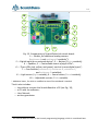
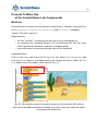
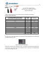
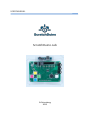
14 10 9 8 1 7 2 3 4 6 5 Fig. 13. Components of ScratchDuino.Lab circuit board: 1— Sockets for additional analog sensors (resistance-A and resistance-B variables1); 2 — Digital input for an external device*; 3 — Button (Button variable); 4 — Speaker; 5 — Controllable matrix of eight LEDs*; 6 — Three LEDs (red, yellow, and green), each at its own digital input*; 7 — Four buttons (resistance-A, resistance-B, resistance-C, and resistance-D variables); 8 — Light sensor (Light variable); 9 — Sound sensor (Sound variable); 10 — Adjustable resistor (Slider variable). * Additional items, for which a modified version of ScratchBoard is needed. The kit also includes: the cable to connect the ScratchBoard to a PC (see Fig. 12); a CD with the software; User Manual; written guarantee. 1 The said variables are used in the Scratch programming language, which is considered later.