1
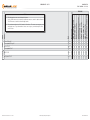
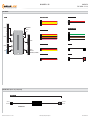
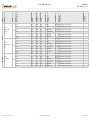
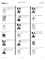
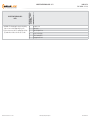
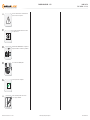
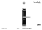
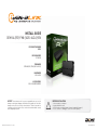
install guide
OEM-AL(RS)-FM6-[ADS-ALCA]-EN
Document number
16348
Revision Date
20140908
fiRmware
OEM-AL(RS)-FM6-[ADS-ALCA]
hardware
ADS-ALCA
accessories
ADS-USB (REQUIRED)


NOTICE The manufacturer will accept no responsability for any electrical
damage resulting from improper installation of this product, be that either
damage to the vehicle itself or to the installed device. This device must be installed by a certified technician. Please review the Installation Guide carefully
before beginning any work.
Automotive Data Solutions Inc. © 2014
BEFORE INSTALLATION
1- Connect module to computer
2- Login to Weblink account
3- Flash firmware to module (module is not preloaded with firmware)
4- Use accessories accordingly (accessories are sold separately)
www.idatalink.com
Page 2 of 14
DOC.: #16348 • 20140908
vehicLe List - 1 oF 1
FEATURES
MODEL
YEAR
DATA IMMOBILIZER BYPASS
TACHOMETER STATUS
HOOD STATUS OUTPUT
BRAKE PEDAL STATUS OUTPUT
RAP SHUTDOWN CTRL
HEATED MIRRORS CTRL
HEATED SEATS CTRL
REAR DEFROST CTRL
A/M RS CTRL FROM OEM REMOTES
NOTES
Fusion STD key AT
13-14 1
•
•
•
•
•
•
•
•
•
Fusion Hybrid STD key AT
13-14 1
•
•
•
•
•
•
•
•
•
Fusion PTS AT
13-14 1
•
•
•
•
•
•
•
•
•
Fusion Hybrid PTS AT
13-14 1
•
•
•
•
•
•
•
•
•
MKZ PTS AT
13-14 1
•
•
•
•
•
•
•
•
•
MKZ Hybrid PTS AT
13-14 1
•
•
•
•
•
•
•
•
•
I This firmware does not cover the doorlock feature.
Use the OEM remote or an aftermarket one button remote to control the doorlock feature.
The OEM remotes remain functional during runtime.
LINCOLN
FORD
Automotive Data Solutions Inc. © 2014
OEM-AL(RS)-FM6-[ADS-ALCA]-EN
INSTALL TYPE
MAKE
II The maximum runtime for all 2013 models is 20 minutes. The remote start sequence can
only be done once. To perform another remote start sequence, start and stop the vehicle
or wait 1 hour.
www.idatalink.com
Page 3 of 14
DOC.: #16348 • 20140908
BOX CONTENTS - 1 OF 1
BOX CONTENTS
WHITE
WHITE
4 PIN BLACK CONNECTOR
6 PIN WHITE CONNECTOR
MODULE
1
2
3
4
5
6
1
2
3
4
5
6
7
WHITE
1
2
3
BLUE
1
2
3
PROGRAMMING
BUTTON
10 PIN BLACK CONNECTOR
7 PIN WHITE CONNECTOR
LED 1
A
B
F
C
E
D
10
9
8
7
6
5
4
3
2
1
4
3
2
1
BLACK
3 PIN WHITE CONNECTOR
DATA CABLE 1
3 PIN BLUE CONNECTOR
DATA CABLE 2
BLACK
DATA PORT
(WEBLINK, RF, TELEMATIC)
WEBLINK CABLE (required accessory sold separately)
WEBLINK CABLE
MODULE
DATA PORT
COMPUTER
USB PORT
4 PIN BLACK CABLE
Automotive Data Solutions Inc. © 2014
OEM-AL(RS)-FM6-[ADS-ALCA]-EN
www.idatalink.com
Page 4 of 14
DOC.: #16348 • 20140908
Automotive Data Solutions Inc. © 2014
COMPONENT
LOCATOR
OBDII
Black
24 pin
20 Blue
(DATA)
OBDII module, driver side dash
~
OBDII
Black
24 pin
19 White
(DATA)
OBDII module, driver side dash
~
CanH 2
OBDII
Black
24 pin
23 Gray/Orange
(DATA)
OBDII module, driver side dash
~
CanL 2
OBDII
Black
24 pin
22 Purple/Orange
(DATA)
OBDII module, driver side dash
~
12V
OBDII
Black
24 pin
13 White/Red
(+)
OBDII module, driver side dash
~
Ground
OBDII
Black
24 pin
01 Black/Gray
(-)
OBDII module, driver side dash
~
CanH 1
OBDII
Black
24 pin
20 Blue
(DATA)
OBDII module, driver side dash
~
CanL 1
OBDII
Black
24 pin
19 White
(DATA)
OBDII module, driver side dash
~
CanH 2
OBDII
Black
24 pin
23 Gray/Orange
(DATA)
OBDII module, driver side dash
~
CanL 2
OBDII
Black
24 pin
22 Purple/Orange
(DATA)
OBDII module, driver side dash
~
12V
OBDII
Black
24 pin
13 White/Red
(+)
OBDII module, driver side dash
~
Ground
OBDII
Black
24 pin
01 Black/Gray
(-)
OBDII module, driver side dash
~
WIRE
COLOR
CanH 1
CanL 1
CONNECTOR
NAME
MODULE
LOCATION
WIRE
DESCRIPTION
POLARITY
13-14
POSITION
MKZ /
MKZ Hybrid
PTS
AT
13-14
CONNECTOR
TYPE
LINCOLN
Fusion /
Fusion Hybrid
PTS
AT
CONNECTOR
COLOR
13-14
FORD
Fusion /
Fusion Hybrid
STD key
AT
YEAR
MODEL
MAKE
TYPE 1 - WIRE CHART - 1 OF 1
OEM-AL(RS)-FM6-[ADS-ALCA]-EN
www.idatalink.com
Page 5 of 14
DOC.: #16348 • 20140908
TYPE 1 - WIRING DIAGRAM - 1 OF 1
MODULE
OBDII MODULE, DRIVER SIDE DASH
A
B
F
STEP 2
C
E DATA
D
A
B
1
2
3
4
5
6
01 GRAY/YELLOW (NC)
02 GRAY/RED (NC)
03 GREEN/YELLOW (NC)
04 GREEN/RED (NC)
05 BLUE/YELLOW (NC)
06 BLUE/RED (NC)
1
2
3
4
5
6
7
01 PINK (NC)
02 PINK/BLACK (NC)
03 ORANGE (NC)
04 ORANGE/WHITE (NC)
05 ORANGE/BLACK (NC)
06 BROWN/YELLOW - CANL
07 BROWN/RED - CANH
1
2
3
01 YELLOW (NC)
02 YELLOW/RED (NC)
03 YELLOW/BLACK (NC)
1
2
3
01 WHITE (NC)
02 WHITE/RED (NC)
03 WHITE/BLACK (NC)
C
D
CONNECT TEMPORARILY
SEE PROGRAMMING PROCEDURE
CANL 1 - 19
CANH 1 - 20
STEP 3
CONNECT TO VEHICLE
SEE PROGRAMMING PROCEDURE
CANL 2 - 22
CANH 2 - 23
BLACK
13
STEP 1
24 23 22 21 20 19 18 17 16 15 14
12 11 10 9 8 7 6 5 4 3 2
1
SELECT ONE OF THE TWO OPTIONS
E
1
2
3
4
01
02
03
04
BLUE/WHITE (NC)
WHITE (NC)
BLACK - GROUND
RED - 12V (+)
WITHOUT A COMPATIBLE ACCESSORY:
CONNECT 12V AND GROUND FROM
MODULE TO VEHICLE.
OR
1
2
3
4
F
1
2
3
4
5
6
7
8
9
10
DATA CABLE
GROUND
12V (+)
GROUND (-) - 01
12V (+) - 13
WITH A COMPATIBLE ACCESSORY:
SEE THE COMPATIBLE ACCESSORIES
PAGE FOR DETAILS.
01 GREEN/BLACK (NC)
02 BLUE/BLACK (NC)
03 RED/WHITE (NC)
04 BROWN (NC)
05 PURPLE/YELLOW (NC)
06 PURPLE/BLACK (NC)
07 WHITE (NC)
08 BLACK/WHITE (NC)
09 GREEN (NC)
10 PURPLE/WHITE (NC)
Automotive Data Solutions Inc. © 2014
OEM-AL(RS)-FM6-[ADS-ALCA]-EN
www.idatalink.com
MODULE PROGRAMMING PROCEDURE - 1 OF 1
01
CONNECT every wire shown in STEP 1 and
STEP 2 of the wiring diagram.
07
Page 6 of 14
DOC.: #16348 • 20140908
Set ignition to ON position.
OFF
ACC
ON START
ENGINE
START
STOP
02
OFF
ACC
Set ignition to ON position.
08
Wait, LED 1 will turn solid RED.
09
ON START
Wait, LED 1 will turn solid GREEN for 2
seconds.
ENGINE
START
STOP
03
Set ignition to OFF position.
OFF
ACC
ON START
ENGINE
START
STOP
04
Set ignition to OFF position.
OFF
ACC
ON START
10
Module Programming Procedure completed.
ENGINE
START
STOP
05
Wait, LED 1 will flash GREEN rapidly.
06
DISCONNECT every wire shown in STEP 2 and
CONNECT every wire shown in STEP 3 of the
wiring diagram.
Automotive Data Solutions Inc. © 2014
OEM-AL(RS)-FM6-[ADS-ALCA]-EN
www.idatalink.com
VALET MODE PROGRAMMING PROCEDURE - 1 OF 1
>>
NOTE: In Valet Mode, the Remote starter is not
functional. Keyless entry, Lock and Unlock will
remain functional. See RF kit user manual for
alternate valet mode programming.
01
Time restriction. Complete next step within 7
seconds.
02
OFF
ACC
ON START
>>
Page 7 of 14
DOC.: #16348 • 20140908
To exit valet mode: repeat steps 1 to 5.
Cycle ignition ON five times [5x OFF/ON]
rapidly.
ENGINE
START
STOP
03
04
Wait, LED 1 will turn solid RED for 2 seconds.
Set ignition to OFF position.
OFF
ACC
ON START
ENGINE
START
STOP
05
Valet Mode Programming Procedure
completed.
Automotive Data Solutions Inc. © 2014
OEM-AL(RS)-FM6-[ADS-ALCA]-EN
www.idatalink.com
Page 8 of 14
DOC.: #16348 • 20140908
MODULE NAVIGATION PROCEDURE - 1 OF 1
>>
It is mandatory to exit the Module Navigation
at the end of this procedure. Failure to exit the
Module Navigation will drain vehicle battery.
To exit the Module Navigation at any time:
Follow STEP 13.
04
>>
Module must be programmed to the vehicle.
05
>>
Use the Module Navigation Chart on the next
page.
06
Set ignition to OFF position.
07
TO ACCESS THE MENUS: Press and hold
programming button until LED 1 turns solid
GREEN.
08
IN THE MENUS: Press the programming
button as many times as the menu number
indicates. LED 1 will flash GREEN an equal
amount of times continuously.
09
01
OFF
ACC
ON START
TO ACCESS THE OPTIONS: Press and hold
programming button until LED 1 turns solid
RED.
10
IN THE OPTIONS: Press the programming
button as many times as the option number
indicates. LED 1 will flash RED an equal
amount of times continuously.
11
TO ACCESS THE SETTINGS: Press and hold
programming button until LED 1 turns solid
GREEN.
12
Configure every other setting and proceed to
step 13.
[Z]
LED 1 will flash GREEN as many times as
the current (or default) setting number,
continuously.
13
MANDATORY: EXIT MODULE NAVIGATION.
Press and hold programming button for 7
seconds. LED 1 will flash RED rapidly. Release
programming button. LED 1 will turn OFF.
[Z]
IN THE SETTINGS: Press the programming
button as many times as necessary to access
your setting. LED 1 will flash GREEN an equal
amount of times continuously.
14
Module navigation completed.
To return to the MENUS: exit the Module
Navigation and redo the Module Navigation
Procedure.
>>
Failure to exit the Module Navigation will drain
vehicle battery.
[Y]
To save and return to the OPTIONS: Press and
hold programming button until LED 1 turns
solid RED.
[Y]
LED 1 will flash RED as many times as the
current option number continuously.
ENGINE
START
STOP
02
03
[X]
Automotive Data Solutions Inc. © 2014
OEM-AL(RS)-FM6-[ADS-ALCA]-EN
www.idatalink.com
Page 9 of 14
DOC.: #16348 • 20140908
[Z] settings
I Default settings are listed in bold.
II Make sure the option is covered on the vehicle before
attempting to change the setting.
[Y] oPtions
moDuLe navigation chaRt:
notes
[X] menus
moDuLe navigation chaRt - 1 OF 1
01-04 N/A
01
N/A
01
enabLe
02
DISABLE*
01
N/A
01
DISABLE
02
N/A
03
LOCK + UNLOCK + LOCK
04
LocK + LocK + LocK
01
03 MIN
02
05 MIN
03
10 MIN
04
15 MIN
05
25 MIN**
06
30 MIN**
07
35 MIN**
08
15 min
09-12 N/A
01
N/A
01
01
N/A
05
TAKEOVER
06
N/A
07
01
FACTORY KEYLESS RS SEQUENCE
CONFIGURATION
08
02-07 Technical Support only
MODULE RUN TIME
N/A
*Vehicle will shutdown when a door is opened.
**The maximum runtime for 2013 models is 20 minutes.
Automotive Data Solutions Inc. © 2014
OEM-AL(RS)-FM6-[ADS-ALCA]-EN
www.idatalink.com
[X] numbeR oF
PaRKing Light
FLashes
Diagnostic
Remote staRteR eRRoR coDes - 1 OF 1
I WARNING: The following applies only when the parking
lights are connected and supported by the system.
03
Foot brake is ON.
04
Hood is open.
II After a remote starter failure, the parking lights will flash
[X] number times to indicate an error code. See table.
05
Engine tach signal is lost.
06
System is in Valet Mode.
07
Vehicle is moving (VSS).
08
Glow plug timeout error.
Remote staRteR eRRoR coDes:
notes
Automotive Data Solutions Inc. © 2014
OEM-AL(RS)-FM6-[ADS-ALCA]-EN
Page 10 of 14
DOC.: #16348 • 20140908
www.idatalink.com
I
II
III
DURING PROGRAMMING
DURING REMOTE START
WITH IGNITION OFF
Automotive Data Solutions Inc. © 2014
Diagnostic
test moDuLe
LeD 1 status
moDuLe Diagnostics - 1 OF 1
Flashing RED
Missing/wrong information from firmware or vehicle.
Solid RED
Module waiting for more vehicle information.
Flashing GREEN
Additional steps required to complete module programming.
Solid GREEN then OFF
Module correctly programmed.
OFF
No activity or module already programmed.
Flashing RED
Module incorrectly programmed.
Solid RED
Module incorrectly programmed.
Flashing GREEN
Module correctly programmed and operational.
Solid GREEN then OFF
Reset in progress.
OFF
Invalid ground when running status from remote starter.
Flashing RED
Module incorrectly programmed or connected.
Solid RED
Module not programmed. Waiting for more vehicle information.
Flashing GREEN
False ground when running status from remote starter.
Solid GREEN then OFF
Reset in progress.
OFF
Module at rest and ready for a remote start sequence.
OEM-AL(RS)-FM6-[ADS-ALCA]-EN
Page 11 of 14
DOC.: #16348 • 20140908
www.idatalink.com
MODULE RESET PROCEDURE - 1 OF 1
01
Disconnect all connectors from module except
the BLACK 4-PIN connector.
07
Reconnect all connectors.
02
Disconnect the BLACK 4-PIN connector.
08
Repeat programming procedure.
03
PRESS AND HOLD programming button while
connecting the BLACK 4-PIN connector.
>>
Failure to follow procedure may result with a
DTC or a CHECK ENGINE error message.
04
Wait, LED 1 will flash RED. RELEASE
programming button.
05
LED 1 will turn RED for 2 seconds.
06
Module RESET completed.
Automotive Data Solutions Inc. © 2014
OEM-AL(RS)-FM6-[ADS-ALCA]-EN
Page 12 of 14
DOC.: #16348 • 20140908
www.idatalink.com
TAKEOVER PROCEDURE - 1 OF 1
>>
All vehicle doors must be closed and locked
prior to remote start sequence.
01
Press unlock on OEM or aftermarket remote
or request switch.
02
OFF
ACC
ON START
Page 13 of 14
DOC.: #16348 • 20140908
DO NOT PRESS BRAKE PEDAL. Set ignition to
ON position. Wait 2 seconds for key validation.
ENGINE
START
STOP
03
Press and release BRAKE pedal.
04
Take over procedure completed.
>>
Failure to follow procedure will result in
vehicle engine shutdown.
Automotive Data Solutions Inc. © 2014
OEM-AL(RS)-FM6-[ADS-ALCA]-EN
www.idatalink.com
instaLLation checKList - 1 OF 1
Page 14 of 14
DOC.: #16348 • 20140908
checKList
1
WARNING: Vehicle engine will start many times. Test in a well ventilated area.
2
Close all vehicle doors, hood and trunk.
3
Press LOCK button three times [3x] rapidly on the OEM keyfob to remote start vehicle.
Question 1: Does the vehicle remote start?
¨
YES: Go to next step.
¨
NO: The module doesn't detect OEM remote lock button from the vehicle communication network. Check all connections, repeat the test and call technical support, if the problem persists.
4
Press LOCK button three times [3x] rapidly on the OEM keyfob to shut down vehicle.
Question 2: Does the vehicle shut down?
¨
YES: Go to next step.
¨
NO: Repeat step. If the problem persists, press on the brake pedal once [1x] to shut down the vehicle and call technical support.
5
RAP Shutdown test
Question 3: Did the radio, interior controls, and headlights turn off within 60 seconds after remote start shutdown?
¨
YES: Go to next step.
¨
NO: Verify the RAP SHUTDOWN connections as illustrated in the wiring diagram. Repeat the test and call technical support, if the problem persists.
6
Open hood.
7
If not already installed, affix the mandatory orange warning sticker under the hood and proceed to next step.
8
Press LOCK button three times [3x] rapidly on the OEM keyfob to remote start vehicle.
Question 4: Does the vehicle remote start?
¨
YES: The vehicle is not equipped with a factory hood pin. Install a mandatory aftermarket hood switch, then repeat the test.
¨
NO: Go to next step.
9
Close hood.
10
Enter vehicle and close the doors.
11
Press LOCK button three times [3x] rapidly on the OEM keyfob to remote start vehicle.
12
Wait for the vehicle to start.
13
Press brake pedal.
Question 5: Does the vehicle shut down?
¨
¨
YES: Go to next step.
14
Exit vehicle.
15
Installation checklist completed.
NO: The module does NOT detect the brake pedal signal. Press LOCK button three times [3x] rapidly on the OEM keyfob to shut down, check the brake connection as illustrated in the wiring diagram, if
applicable, and call technical support.
Automotive Data Solutions Inc. © 2014
OEM-AL(RS)-FM6-[ADS-ALCA]-EN
www.idatalink.com