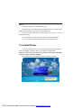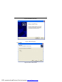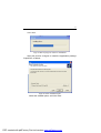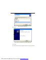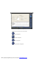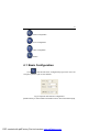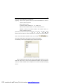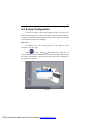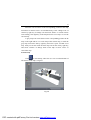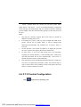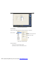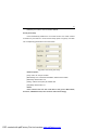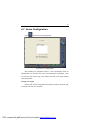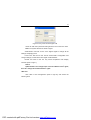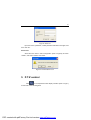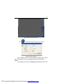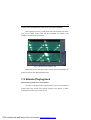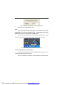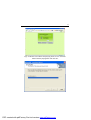
1
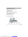
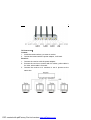
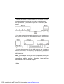
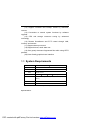
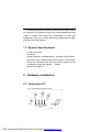
1 Manual of WirelessNetwork DVR Thank you for choosing the four channel wireless receiver. Please read this manual carefully before you use it, and it will benefit you to use this product better. This product is suitable for the supervision of the places such as supermarkets department sores, houses, workshops, building sites, hospitals, schools, resident area, traffic and so on. Function Feature 4-channel real time receiving, quad picture, recording to pc, Internet view, motion detection remote control. I. Basic Specification of Reciever USB: 2.0 Receiving Frequency 2.400GHz-2.483GHz Frequency Tune PLL Receiving Sensitivity 85dB Video Output 75 /1Vp-p Audio Output 10K /500mVp-p Video System PAL/NTSC/SECAM Compatible Validity Distance 150m(Open area) Auto Switch Output Widows Default is Switch once every 5 seconds Power adapter Input AC Power Frequency 50/60Hz Voltage 100~240V Output DC Power 5V/1.5A Power Consumption 8W Outline Size 205 x 120 x 43mm Weight 520g PDF created with pdfFactory Pro trial version www.pdffactory.com 2 II. Basic Specification of Camera Transmitting Frequency: 2.400GHz-2.483GHz Image Device: 1/3CMOS Horizontal Definition: 380 TVL TV System: PAL/NTSC Validity Pixel: PAL: 628x582, NTSC: 510x492 Minimum Illumination: 3Lux/F1.2 & 0Lux (IR ON) Validity Distance 150m(Open area) Working Temperature: -10 ~50 Night vision distance: 10M III. Sketch Map of the Product Antenna Channel Key 1 Channel Key 2 Channel Key 3 Channel Key 4 Auto Switch Channel Key PDF created with pdfFactory Pro trial version www.pdffactory.com 3 IV. How to use Camera: 1. Install the camera where you want to monitor 2. Connet the camera with the power adatper, it will work. Receiver: 1. Connect the receiver with the power adapter. 2. Connect the receiver to monitor with AV cables, yellow cable is for video, white cable is for audio. 3. Connect the receiver to 4 monitors to see 4 pictures at the same time. PDF created with pdfFactory Pro trial version www.pdffactory.com 4 4. Connect the receiver to one monitor to see one picture one time, press the channel switch keys on the receiver, to get the picture form right channel, or press AUTO key to see 4 piectures by anto change. 5.If you want to see 4 pictures at the same time on one monitor, you can connect the receiver to 4 channel QUAD device, and connect the 4CH quad to monitor: 6. Connect the receiver to PC with USB cable, to see 4 real time pictures from internet, and recording to pc hard drive, please see the detail instructions from CD Receiver USB DVR FUNCTION USER MANUAL Note: The distance among the four transmitters should be over 2M, and the same distance with that between the transmitters and the receiver, otherwise, there will be interference for the received images. V. FAQ: PDF created with pdfFactory Pro trial version www.pdffactory.com 5 1)The indicator light does not work Please check whether the power of the receiver has been inserted correctly and the switch was turn on. 2) There is no image or the images are not clear Please check power has been switched; Please check if the distance is too long between camera and receiver, or if there are any electromagnetism obstruction around (e.g. steel construction will counteract transmitting signals.) Please check whether the frequency of the transmitter is the same with the receivers or not. (Two cameras with the same frequency can not work properly within effective distance, thus interference will be caused) Please confirm the receiver antenna has been fixed tightly. Please keep far away from big copper or iron electromagnetism obstruction. High-power transmitter in the same frequency and car broadcasting station may also cause interference. . What is in the box: Receiver: Power adapter of receiver: Camera: Power adapter of camera: AV Cable: Manual: USB cable: Warranty Card: 1 pc 1 pc 1~4pcs (optional) 1~4pcs (optional) 5pcs 1pc 1pc 1pc PDF created with pdfFactory Pro trial version www.pdffactory.com 6 . USB DVR FUNCTION Introduction Summarization In this manual, you will learn how to install the hardware and driver (software), and how to setup the systems of this range of products. Please make sure your operations with the products are strictly in accordance with the manual, so as to keep the stability of the digital surveillance systems. The following are standard functions of the products: (1) Schedule record mode Users can choose any term in a day to record and set up record modes, i.e. sensor alarm record, motion detection record, manual record, Schedule Record. (2) Motion detection mode Motion detection areas are adjustable and maximum 16 areas for each channel. Users can also set motion detection sensitivity for each channel. The system begins to record only when motion of the detected object happens, and it will stop recording after a certain period, this function is adjustable by users. (3) Sensor alarm record mode With extra alarm board, the system enables alarm input and output. (4) Recycling record mode Users can set recording storage sequence for HDD partitions. PDF created with pdfFactory Pro trial version www.pdffactory.com 7 The recording storage will automatically swap to the next partition when it is full. If all the partitions are full and recycling record mode is enabled, the former recorded data will be covered by new data. Users can also set HDD minimum storage alarm. Then once the present storage space is less then the minimum storage and recycling record mode is not enabled, the record will automatically stop. (5) P.T.Z control function Support a number of decoders. Users can control multiple speed domes and integrative cameras, including pan, tilt, zoom, a focus and iris adjustment for P.T.Z devices. Support preset point and auto scout. (6) Users management Different users have different rights, user names and passwords, so as to ensure system security. (7) Multi-channel display Support different multi-channel display modes, full screen display and auto dwell display. (8) Support 320x240 / 640x480 (NTSC), 352x288 / 704x576(PAL) standard resolutions. (9) Image color adjustable for each channel, including contrast, lightness, hue and saturation. (10) MPEG4 compression format, greatly reduce HDD usage (11) Powerful video playing back functions, including playing back, pause, stop, fast-forward, single-frame play and image capture. (12) Support advanced search mode. Users can search by date/time, camera, record mode, and random combination of the three methods. PDF created with pdfFactory Pro trial version www.pdffactory.com 8 (13) Support recorded files backup, delete by date/time, camera. (14) Convenient to extend system functions by software upgrade. (15) CPU and storage resources saving by advanced technology (16) Remote Surveillance and P.T.Z control through LAN, Intranet, and Internet. (17) Support alarm pre-record. (18) Support buzzer, email alarm out. (19) Can greatly decrease fragmented files while using NTFS partition. (20) User-friendly graphical user interface. 1.1 System Requirements CPU Motherboard Intel P4 Celeron processor Intel 845/865/915 series HDD 80G minimum RAM 256M minimum VGA GeForce2 GeForce4 OS minimum 1700MHz FX5200 ATI Rage128 Windows 2000(SP4 above)/2003(SP1 above)/XP(SP2 above) DirectX 9.0 USB 2.0 Table1.1system requirements Special Notice: PDF created with pdfFactory Pro trial version www.pdffactory.com 9 If recorded disk partition’s format is FAT32 and the system has run for a long time, the system will create a lot of data fragments that may results in system runs slowly. It’s recommended to make disk defragmenter every 10 to 30 days. We strongly suggest that use NTFS format for record disk partition. 1.2 System Specifications Format: PAL/NTSC Resolution: Support 320x240 / 640x480 (NTSC), 352x288 / 704x576(PAL), Maximum Frame rate per channel: 25 fps (PAL), 30 ftp (NTSC) Screen set: resolution 1024×768, color quality 16 bits or 32 bits Compression code rate: 50kbps 1.2Mbps Data format: MPEG4 2 Hardware installation 2.1 Connect to PC Fig2.15 USB Video Capture Card PDF created with pdfFactory Pro trial version www.pdffactory.com 10 Notice: Make sure that your PC USB interface is 2.0 Please accord to the following steps to safely remove the receiver: Right clicks on the Taskbar Stop device pull out the USB cable. Using with other USB device simultaneously may cause PC cannot identify the receiver. Do not insert two or more USB video capture cards simultaneously. Do not use with the other PCI video capture card simultaneously. 2.2 Install Driver Insert the CD into the CD tray, and run Setup.exe program to install the driver. The default installation path is C:\Program Files\SuperDVR. Notice: In case it warns that ‘Can’t find card’ when running the SuperDVR software, please restart the computer. Run Setup.exe, and the installation interface appears as below: PDF created with pdfFactory Pro trial version www.pdffactory.com 11 Fig2.30 Installation interface Fig2.31 Welcome page Select Next, Fig2.32 Select video format PDF created with pdfFactory Pro trial version www.pdffactory.com 12 Select Next, Fig2.33 Rate of progress of driver installation After this process it begins to install the application package SuperDVR, as below: Fig2.34 Select installation pass Select the suitable option, and click Next. PDF created with pdfFactory Pro trial version www.pdffactory.com 13 Fig2.35 Register application Click Next, Fig2.36 Driver and application installation finished Click Finish Now, after all the processes are finished, restart the computer and launch PDF created with pdfFactory Pro trial version www.pdffactory.com 14 the surveillance program. It will create a shortcut on the desktop. Fig2.37 Shortcut of SuperDVR Notice: When you install the driver software on Microsoft VISTA system, you need select the option as below figure first. And steps of install the driver software on Microsoft VISTA system are the same as on Microsoft XP system. Fig2.38 Install the Software on VISTA In case users cannot run the SuperDVR program, users restart the computer. PDF created with pdfFactory Pro trial version www.pdffactory.com 15 3 Main display Interface Run SuperDVR program and the main display interface appear as below: Fig3.1 SuperDVR Main Display Interface 3.1 Display Control Panel Display Control Panel PDF created with pdfFactory Pro trial version www.pdffactory.com 16 Fig3.2 Display control panel Display control panel includes Display Mode buttons and disk free space indicator, Auto Dwell button, 1, 4, 6, 8, 9, 13, 16channels display buttons. Every button has its built-in indicator light. When switch on and off the buttons, the relative indicator lights turn on and off to indicate the working status. Notice: Users can judge which buttons are working by the color of the buttons. Free space Display Modes 1CH 4CH 6CH 8CH 9CH 13CH 16CH Fig3.3 Display Modes Panel Notice: In case the card installed is 4CH CARD, then only 1CH and 4CH buttons are valid. Flip Pages When the display mode is 1CH, 4CH, 6CH, 8CH, 9CH or 13CH, click , system will display the next page according to the display mode. Auto Dwell display Mode In case users want to see all the channels in sequence, then click and enter Auto Dwell display mode. PDF created with pdfFactory Pro trial version www.pdffactory.com 17 Quick Switch In case the present display mode is 4CH, 9CH or 16CH, by clicking any image or the present display mode is 6CH, 8CH or 13CH, by clicking the bigger image, the display will quickly switch to corresponding single channel display mode. When the present display mode is 6CH, 8CH or 13CH, by clicking any image other than the bigger one, users can change the position of the image with the bigger one. By clicking the single image again, it will return to the former display mode. 3.2 Login , and login window appears. Input the user name and Click password, the default user name is SYSTEM with no password, users can access to the main interface. Users can change password for SYSTEM and create new user names and passwords once has entered the system. Time & Date Login Search and Playback Configuration PTZ Control Exit Display Mode Panel Alarm out status Camera status PDF created with pdfFactory Pro trial version www.pdffactory.com 18 Fig3.4 Main Interface 3.3 Record Record Modes According to different record triggering methods, the USB video capture cards offer users with 4 kinds of record modes: (1) Schedule record mode (timer) (2) Manual record mode (3) Motion Detection record mode (4) Sensor Alarm record mode Motion Detection record mode and Sensor Alarm record mode are together called as Alarm Record. Multiple cameras record In case users use multiple cameras to record, every camera works separately and the record file also saved separately. The parameters, i.e. camera ID, record date/time and record mode are all saved together with the record file. Record Setup Fig3.5 Record Configuration Panel PDF created with pdfFactory Pro trial version www.pdffactory.com 19 In the Record Panel of the Basic Configuration page, users can set all kinds of necessary parameters for recording. [Time stamp]: By selecting the options, the record date / time message appears in the record file images. [Switch]: By selecting the options, users can turn on corresponding cameras. In case there is no camera for some channel, dont select the option so as to save system resource. [Manual record]: By selecting the options, the relative camera images will be recorded and saved all the time. [Manual recording frame rate]: Select the record frame rate for manual record mode [Schedule Record]: Schedule record option. [Schedule Record Frame Rate]: Select Schedule Record frame rate [Motion Detection]: By selecting the options, users can set relative channels record mode as motion detection [Motion Record Frame Rate]: Select record frame rate for Motion Detection record mode [Sensor Record Frame Rate]: If sensors are utilized to trigger recording, users can select record frame rate here. [Camera Security]: The users are divided into three standards: Normal user, Power user and Administrator. By selecting the options, only administrators can see the corresponding channels. [Record Quality]: Select record image quality here. [Audio In]: SuperDVR4.3 system can support one channel of microphone audio input signal on the PC motherboard and audio inputs on the card if it has.. Users can choose one video channel associate these audio signals. Note: Users can select more than one record mode. PDF created with pdfFactory Pro trial version www.pdffactory.com 20 Record Status Panel Fig3.6 Record Status Panel and Alarm Output Status Panel Meanings of indicator light colors in row one are as below: (1) Normal State (2) Manual Record State (3) Schedule Record State (4) Motion Detection Record State (5) Sensor Alarm Record State (6) Video Loss State When the indicator light color turns into in row two, it means there is alarm output. Manual Record Mode Manual Record mode is the most commonly used record mode. In case there is any special event happens, users can select this record mode and record timely. Note: You can select high frame rate for short time manual record, while select low frame rate for long time Schedule Record. PDF created with pdfFactory Pro trial version www.pdffactory.com 21 Sensor Alarm Record Mode Users can use sensors to trigger sensor alarm record for relative channels. At that time, the record status indicator light will turn red . Motion Detection Record Mode It will enable the system to detect image changes and begin to record by activating motion detection and motion alarm record. For instance, somebody opens the door, and the system detects image changes and begins to record, then users can play back the recorded file and find out who opened door. When there is no movement, the system wont record and thats helpful for saving system resource, and convenient for searching for event record file. The indicator light color in the record status panel is yellow . Note: Users may need to setup in three places so as to enable motion detection record. (1) Select Motion Detection for certain channels in Basic Configuration (2) Configure the motion detection areas for certain channels in Motion Detection configuration (3) Configure working schedule for certain channels in Schedule configuration Schedule Record Users can set working schedule for all kinds of record modes in Schedule configuration. The green light in record status panel shows the corresponding channel is in Schedule Record mode. Users can change record mode to manual record at any time, and the green light PDF created with pdfFactory Pro trial version www.pdffactory.com will change into 22 blue light . Please refer to chapter 4.4 for details. Recycling Record If users enable Recycling Record function and all the selected HDD partitions are full, the former record data will be covered by the latest record data. Users can set recording storage sequence for HDD partitions. The recording storage will automatically jump to the next partition when its full. If all the partitions are full and recycling record mode has been enabled, the new data will overwrite the former recorded data automatically. Users can also set HDD minimum storage alarm. Then once the present storage space is less then the minimum storage and recycling record mode hasnt been enabled, the record will automatically stop. 4 System Setup Click and enter the main setup interface. PDF created with pdfFactory Pro trial version www.pdffactory.com 23 Fig4.1 Basic Configuration The definitions of the buttons in Fig4.1 are as below: Basic Configuration Schedule configuration Video configuration Motion Detection Configuration PDF created with pdfFactory Pro trial version www.pdffactory.com 24 Alarm Configuration P.T.Z Configuration User Configuration Return 4.1 Basic Configuration and enter the basic configuration page where users can Click setup the system or just use the defaults. Fig4.2 Caption and General Configuration [Dwell Interval.]: If users enable Auto Dwell function in the main interface page, PDF created with pdfFactory Pro trial version www.pdffactory.com 25 users can set the dwell time of a page here. [Caption]: There are four options, None, ID, Name and ID/Name for users to select for all the channels. None means no title; ID means camera numbers, i.e. 1, 2, 3 and so on Name means camera names, i.e. Cam1, Cam2 and so on ID/Name means both camera number and camera name, i.e. 1/Cam1, 2/Cam2 and so on [Resolution]: There are four options,320 240 352 288 352 240 640 480 for users to select for all the channels. As the video may have interlace lines if the users select 640x480, users may choose for solve this problem, but it will occupy much more CPU loading. The following is about record data storage. Please check Fig4.3 Fig4.3 Record data storage precept Above, SuperDVR system shows all the available HDD partitions for users. Users can select one or more of the partitions that will be used in sequence from up to bottom. Please refer to chapter 3.3.8 to learn more about recycling record. PDF created with pdfFactory Pro trial version www.pdffactory.com 26 In the following area in the basic configuration page, users can input the computer user name and password in the relative boxes. Then when restarting the computer system, it will access to the system with the user name and password input in the boxes. Fig4.4 Computer System Reboot setups As the windows system may become unstable after a couple of days continue operating, which will cause SuperDVR system unstable? Then users should reboot the computer. Select the interval by day, and set which will guide the system to reboot automatically according to the setups. Click to return to the main display interface. 4.2 Video Configuration Click and enter the video configuration page as below. Users can change the values of corresponding items, i.e. contrast, brightness, hue, saturation, auto gain, by drawing the levers on the bars. Click Default, and all the values will return to the default value. PDF created with pdfFactory Pro trial version www.pdffactory.com 27 Fig4.5 Video Configuration Definitions of the setup items: [Contrast]: set image color contrast [Brightness]: set image brightness [Hue]: set image hue [Saturation]: set image Saturation [Auto Gain]: users can set it as auto or manual. [Default]: load defaults Motion Detection configuration Click and enter Motion Detection Configuration page as below: PDF created with pdfFactory Pro trial version www.pdffactory.com 28 Fig4.6 Motion Detection Configuration Definition of the setup items: [Sensitivity]: users can set motion detection sensitivity here. [Select all]: select all the areas of the channel as detection area [Clear]: clear all the detection areas and then users can select customized detection areas by cursor. Set Motion Detection Area In case users want to customize the detection areas for a certain channel, first select the camera, then select Clear and drag the cursor in the box in the left side. Now, users can see a green box appears which shows the motion detection area. Users can select maximum 16 customized areas for each channel. By click Clear, users can clear all the selected areas. Set Motion Detection Sensitivity Draw the bar and select a certain value for motion detection sensitivity. PDF created with pdfFactory Pro trial version www.pdffactory.com 29 4.3 Schedule configuration Click and enter Schedule Configuration page as below: Fig4.8 Schedule Configuration This system offers the users with powerful schedule configuration options. Every channel has three kinds of record modes, i.e. schedule record, motion detection record and sensor alarm record. We provide users to set schedules from Sunday to Monday separately for all of the three record modes. Sensor alarm record mode has the highest priority among all record modes. Here users can set schedules for it. When users need to edit schedule for a channel, first select the camera name in the three record modes group, and select the color bars on the right side, then select Edit to edit schedules. Click Add to add schedule for a certain channel. Note: the added schedule should not be reduplicate to the former settings. PDF created with pdfFactory Pro trial version www.pdffactory.com 30 Click Delete to delete schedule. Click Clear All to delete all the schedules of a certain channel. See the Fig4.8 and learn how to edit schedules for a channel: Fig 4.9 Edit Schedule 4.4 Motion Detection Alarm Configuration Alarm Triggering Conditions Configuration The system can receive alarm both from local place and network (1) Local place alarm record triggering conditions configuration Fig 4.10 Local place alarm triggering conditions configuration Relative Explanations: [Buzzer]: Users can select whether to open the computer buzzer if the alarms have been triggered and also select how long the buzzer rings [PreRecord]: Users can select whether to enable alarm pre-record and PDF created with pdfFactory Pro trial version www.pdffactory.com 31 also pre-record time. [Motion Holding Time]: Motion sensor may detect some movement, only if the movement lasts for a period exceeding the default time, then the alarm record will begin and buzzer beeps. [Disk Shortage Alarm]: If the HDD available space is less then the set value, the buzzer will beep if Buzzer has been selected. (2) Alarm output terminal in LAN Fig 4.11 Alarm output terminal in LAN Select Remote Alarm, and enter the area as Fig4.10 shows. Click Add to add alarm output terminals in LAN. Look the figure below: PDF created with pdfFactory Pro trial version www.pdffactory.com 32 Fig 4.12 Add alarm output terminal in LAN Find the terminal computer and click OK, and users can see the name of the selected terminal will appear in the box as below: Fig4.13 List of alarm output LAN terminals Note: this function is only valid in LAN, not in Internet. PDF created with pdfFactory Pro trial version www.pdffactory.com 33 Alarm Record Fig4.14 Alarm trigger method configuration Every sensor can trigger multiple channels to record. For example, if users select CAM1, CAM4 and CAM5 for Sensor2, then once the sensor is activated, CAM1, CAM4 and CAM5 will begin to record. Users can also select the voltage, high and low, for alarm signals. PDF created with pdfFactory Pro trial version www.pdffactory.com 34 Alarm Output Fig4.15 Alarm output Configuration [Video Loss]: Users can select alarm output for this option. For example, users select alarm_out1 and alarm_out3 and remote alarm for video loss. Then video loss of any channel will trigger alarm_out1, alarm_out3 to show red light in the Alarm output status panel (refer to Fig3.6 for reference), and the system will give out related warning message to the terminals in List of alarm output LAN terminals (refer to Fig 4.12) [Disk Alarm]: when HDD available space is less than the set value (refer to Fig4.9), it will trigger selected alarms. [Sensor 1]: If users have mounted sensors, when the sensors have been activated, then it will trigger the selected output alarms. [Motion 1]: Users can set motion detection alarm output by different alarms and remote alarm. PDF created with pdfFactory Pro trial version www.pdffactory.com 35 Auto Mail Function Press in the main interface and access to the following Alarm Configuration area where users can make motion detection alarm setup, sensor alarm setup and short of HDD space alarm setup. Now users can select the above-mentioned alarms to be output by Auto Mail. Fig 4.16 Alarm output configuration Click Auto mail icon on the top left side and enter the following area to make Auto Mail setup: PDF created with pdfFactory Pro trial version www.pdffactory.com 36 Fig 4.17 AutoMail setup interface In this area, users can set receiver and senders E-mail SMTP server and address. Note: the address of receiver and sender can be the same. Receivers E-mail Address Senders E-mail Address Senders SMTP Server PDF created with pdfFactory Pro trial version www.pdffactory.com E-mail Subject Senders Password Sender User Name 37 Fig4.18 Auto Mail Setup To test the settings, click Send Mail Test. If all settings are okay, message Message Sent Successfully will pop up. If some settings are wrong, there will pop up corresponding warning message. Enable Attachment, then the present image when an alarm triggered will be sent to appointed mailbox. Channel Name Display Time Image format Resolution Fig 4.19 Attachment Setup Note: for every alarm event, only one picture will be sent. Users can put into a short message to make introduction of the Auto Mail, so the receiver will know what happened. PDF created with pdfFactory Pro trial version www.pdffactory.com 38 4.5 E-map Configuration A E-map is used to show full geographic range covered by the whole monitoring system in the form of map .An E-map has the feature of simple operation and direct display of status and it is generally graded or tiered in the form of a tree diagram. Edit a map In windows OS, Save related pictures in the folder of My computer,As bmp or jpg. Click to enter Emap Emap Edit,press right key of Load Picture in the default interface of map and select the required map file in the related folder, open the file and the map will be displayed in this interface, as fig 4.20 Fig4.20 PDF created with pdfFactory Pro trial version www.pdffactory.com 39 Draw the icon of camera to the corresponding position in the map, maximum 16 cameras can be set simultaneously, Click change icon of camera by right key to change icon and click delete to cancel camera. After editing, click right key in the map and select save map to save the current map. A gray map icon can be drawn to the corresponding position in the map on the right and set it as a sub-map of the current map, or click the gray map icon on the left by right key and select open to build a new map. And you can also click the blue map icon on the left by right key, and select rename to change name of the map or select close to cancel this map. View the map to enter Emap, where the user can view distribution of Click all cameras in the map, as fig4.21 Fig4.21 PDF created with pdfFactory Pro trial version www.pdffactory.com 40 When a channel alarm, the camera icon will flash yellow alarm signal. Select Auto show , in case of accident alarming, an alarming screen will pop out automatically and you can know about the alarming position rapidly. Click the camera head by right key to show the screen on the spot. Note: 1. The map tree currently supports three levels and it is invalid for addition exceeding three levels. 2. For loading of a picture, when any side of length and width of the picture exceeds size of picture frame, it will be enlarged and shortened proportionally and standard size of picture frame is 833*678. 3. On this interface, click camera by right key to display the spot and the 3316 card does not support this function temporarily. 4. If Auto close is set in case that E-map pops up by automatic alarming, the E-map interface set with Holding time without any operation and alarm will be close automatically. Auto Close is invalid when the E-map is opened manually. 5. The map in the E-map is the default demonstration map, and the user can invite an engineering merchant to make the practical map or draw a map by their own according to their actual needs, then scan and save it in the computer to picture. 4.6 P.T.Z Control Configuration Click and enter the following area: PDF created with pdfFactory Pro trial version www.pdffactory.com 41 Fig4.20 PTZ configuration panel Protocol Setup Users can select different protocols, serial port number for P.T.Z devices. Select Camera Select PTZ Protocol Select Select Protocol COM PTZ Address Fig4.21 P.T.Z protocol setup Relative Definitions: [Port]: users can set serial port number [Protocol]: P.T.Z device communication protocol PDF created with pdfFactory Pro trial version www.pdffactory.com 42 [Address]: P.T.Z device communication address Serial ports setup Users should firstly enable the P.T.Z control function of a certain camera and select a port number in P.T.Z Protocol Setup (refer to Fig4.22), and then set corresponding parameters in the area below: Fig4.22 P.T.Z serial port setup Relative explain: [Port]: users can set port number [Baud Rate]: set P.T.Z device Baud Rate, default value is 9600 [Data bits]: default value is 8 [Parity]: odd and even parity bit, default Null [Stop Bits]: default value is 1 Notice: Users should look into the P.T.Z device and get the Baud Rate, Protocol, and Address first, then set their values accordingly. PDF created with pdfFactory Pro trial version www.pdffactory.com 43 4.7 Users Configuration Click and access the following area: Fig4.23 User configuration After installing the SuperDVR system, it will automatically create an administrator user of which user name is SYSTEM with no password. Users can use this user name to log in the system and Add, Edit and/or Delete users parameters. Change User rights Select a user in User Configuration area (refer to Fig4.23), and click Edit and enter Edit User area, as below: PDF created with pdfFactory Pro trial version www.pdffactory.com 44 Fig4.24 User password and rights edit Users can edit users password and rights here, but not the user name. Note: The system offers three kinds of rights: Administrator: this kind of user of the highest rights to change all the settings and playing back. Power user: this kind of user cannot access Basic Configuration and change settings, but has all the other rights of Administrator. Normal: this kind of user can only access SuperDVR main display interface (refer to Fig3.1) Notice: Administrators can change Power users and Normal users’ rights, but can’t change other administrators’ rights. Add User Click Add in User Configuration (refer to Fig4.25), and access the following area: PDF created with pdfFactory Pro trial version www.pdffactory.com 45 Fig4.25 Add user Input user name, password, confirm password and select user rights, and then click OK. Delete User Select the user name in User Configuration (refer to Fig4.26), and click Delete, and confirm delete. See below: Fig4.26 Confirm delete user 5 P.T.Z control Click in the SuperDVR main display interface (refer to Fig3.1) and access to the following area: PDF created with pdfFactory Pro trial version www.pdffactory.com 46 Fig5.1 P.T.Z control interface Users can control P.T.Z devices by the function buttons on the right side, see as below: Goto Preset Point Preset and Group PAN and Tilt Focus Zoom In/Out Iris PDF created with pdfFactory Pro trial version www.pdffactory.com 47 Fig5.2 P.T.Z Control function buttons panel In the upper circle, there are five function buttons, i.e. upward button, downward button, leftward button, rightward button and stop button. The other buttons are Focus buttons (+ and -), Zoom buttons (+ and -), Iris buttons (+ and -). Click and to increase and decrease the corresponding values. When users need to utilize P.T.Z control, first enter P.T.Z Control Interface (refer to Fig5.1), and click the corresponding channel (users can see a red fringe around the channel), then users can begin to control the enabled P.T.Z control enabled camera. Notice: After pressing left mouse button on any function button in P.T.Z Control Function Buttons Panel (refer to Fig5.2), PTZ device starts moving, when user releases it, PTZ device stops moving. Fig 5.3 Speed adjustment Users can select different Pan speed, Tilt speed, Focus speed and Zoom speed for P.T.Z devices. [Pan Speed]: set horizontal rotating speed [Tilt Speed]: set vertical rotating speed [Focus Speed]: set camera focus speed [Zoom Speed]: set zoom in/ zoom out speed Click and a pop-up window will appear; users can choose PDF created with pdfFactory Pro trial version www.pdffactory.com 48 different preset or group set. Fig 5.4 Preset and group select Click to set Preset point and change Preset point name. Every Group includes multiple Preset points. In case users select preset1, preset2 and preset3 for group1, preset1, preset2 and preset3 will be automatically accessed in sequence after users select group1 for auto scout. PDF created with pdfFactory Pro trial version www.pdffactory.com 49 Fig 5.5 Preset Click , a pop-pup window as following will appear: [Dwell]: users can set the dwell time of a page here. PDF created with pdfFactory Pro trial version www.pdffactory.com 50 Fig 5.6 Group configuration 6 Record Search and Playing back Click in the SuperDVR Main Display Interface (refer to Fig3.1) and access to the following areas: Fig6.1 Search and playing back Interface This interface is divided into 4 parts, i.e. record search area, record playing back area, record play area and other functions area. Press and return to the live surveillance status. PDF created with pdfFactory Pro trial version www.pdffactory.com 51 6.1 Record Search Fig6.2 Record search area A, B and C marks the areas of three search methods. st A: Search by date (range from Jan 1 , 1971 till now) B: Search in backup file and original file C: Search by record mode. This is useful when user wants to look through some important events. Users can select one or above of the three searching methods to search for needed record file. PDF created with pdfFactory Pro trial version www.pdffactory.com 52 6.2 Record Playing back and Control Fig6.3 Record playing back and control Explain of the button function: : Play / Pause : Stop : Play backwards. This button is valid when playing back by single channel : Previous Section. This button is valid when playing back by single PDF created with pdfFactory Pro trial version www.pdffactory.com 53 channel : Next Section. This button is valid when playing back by single channel : Previous Frame. This button is valid when playing back by single channel playing back pause mode : Next Frame. This button is valid when playing back by single channel playing back pause mode Users can select suitable play speed in the area as below: Fig6.4 Play Speed Controller The following area shows the record files of different channels: Fig6.5 Record Files Browser The upper bar shows the hours in a whole day. Click the bar, and it will be magnified 10 times, therefore users can see the detailed time marks. When searching for a certain section of the file, users can draw the scrolling-bar to the area that most likely contains the needed section. If necessary, click the bar once and see the magnified time marks for precise search. The left side shows the available channels. When a certain channel has been selected for playing back, the background color will be highlighted, or its PDF created with pdfFactory Pro trial version www.pdffactory.com 54 dark gray, and a tick sign will appear beside the channel title. The main area at the center gives details of the record files. Different colors of the bar show different kinds of record modes of the files. The following are the definitions of the color bars: Manual Record Events Schedule Record Events Motion Detection Record Events Sensor Alarm Record Events Click to play selected record files. The system offers 1Ch, 4CH, 9CH and 16CH playing back modes. The following is multiple channels playing back control area: Fig6.6 Multiple Channels Playing back Control The system default playing back mode is one channel. Thats Camera1. In case users need to change to other channels, then click and the following channel configuration window will appear, as below: Fig6.7 Channel Configuration Window for 1 Channel Playing back Mode Note: Take 16CH card for example. But in fact, 4 pieces of 4CH cards can make the same effect. Users can select one channel from all the available channels for playing PDF created with pdfFactory Pro trial version www.pdffactory.com 55 back. In case user needs to play back 4 channels at the same time, then click , and the following channel configuration window will appear, as below: Fig6.8 Channel configuration dialog for 4-channel playing back mode Users can select any four channels from all the available channels for playing back. The system offers quick select methods for users. For example: by selecting Third 4 Channels Camera9, Camera10, Camera11, and Camera12 will be quickly selected simultaneously. In case user need to play back 9 channels at the same time, then click , and the following channel configuration window will appear, as below: PDF created with pdfFactory Pro trial version www.pdffactory.com 56 Fig6.9 Channel configuration window for 9-channel playing back mode Users can select any 9 channels from all the available channels for playing back. Users can also use the quick select methods by the system. In case user needs to play back 16 channels at the same time, then click , and the following channel configuration window will appear, as below: Fig6.10 channel configuration window for 16-channel playing back mode Then click OK to play back. Tips: Click any channel and magnify it to see the single channel. Click again to return to the former playing back mode. 6.3 Other Functions Record File Backup Click and enter the following menu: PDF created with pdfFactory Pro trial version www.pdffactory.com 57 Fig6.11 Recorded files backup Users can select corresponding cameras and copy the record files to another path in this area. This is the file backup function of the system. The interface is divided into four areas: A: Camera Selection Area B: Time and Date Selection Area C: Operation Area D: Information Area In A area, users can select one or more cameras; In B area, users can set start time/date and end time/date, and then backup the files recorded by channels selected in A area by the time interval; In C area, users can set backup path Click Start to backup files. Delete Record Files Click and the following window will appear: PDF created with pdfFactory Pro trial version www.pdffactory.com 58 Fig6.12 Delete recorded files Users first select the channel on the left side, and then select start time/date and end time/date of the record files, click Start to delete files. Capture Pictures The definitions of the function buttons are as below: : Capture picture : Print setup : Print captured picture Notice: Only in one channel playing back pause mode (refer to Fig6.1) this function is valid. When in single channel playing back pause mode, automatically the following color control panel (Fig6.12) will appear, by which user can make PDF created with pdfFactory Pro trial version www.pdffactory.com 59 color rectification for the present channel, including brightness, contrast, saturation and hue, and press Default to recover to the original settings. Fig6.13 Color control panel When in the single channel playing back pause mode, click and the following window will appear as below: Fig6.14 Capture multiple images in sequence Select path and click Save to save the picture. User can also print the images that have been captured. PDF created with pdfFactory Pro trial version www.pdffactory.com 60 Click and make corresponding print setup as below: Fig6.15 Print setup Click users can have print preview as below: PDF created with pdfFactory Pro trial version www.pdffactory.com 61 Fig6.16 Print preview Select and then click or picture upward, downward, leftward and rightward. Select click to move the and then to zoom in and out the image. Press , return to the original settings. Press Print in the print preview window, users can print the image directly. Image Zoom In / Out When in single channel playing back state, the zoom control icons will appear. Select and click on the channel will zoom out the image. By clicking continuously, the image will be zoomed out continuously. Select effect. Click and do the some operations to get the opposite and recover the original size. Take the following three PDF created with pdfFactory Pro trial version www.pdffactory.com 62 pictures for example, Fig6.17 Example: original size PDF created with pdfFactory Pro trial version www.pdffactory.com 63 Fig6.18 Example: zoomed out PDF created with pdfFactory Pro trial version www.pdffactory.com 64 Fig6.19 Example: zoomed in 7 Remote Surveillance and Playing back 7.1 Remote Live Surveillance This surveillance system supports Remote Surveillance through LAN, Internet and Intranet. Simply enable web cam function of the system on a computer which is connected to Internet, and the computer system will become an Internet web cam server. On any other computer that connects to Internet or the same LAN network, input the SuperDVR server address in IE browser, the end users can get high quality real time image from the server and also control the P.T.Z devices. Remote Surveillance Server Configuration Users should firstly enable the Web Camera Services in Basic Configuration (refer to Fig4.1) and set other settings as below: PDF created with pdfFactory Pro trial version www.pdffactory.com 65 Fig7.1 Web cam server configuration [HTTP Port]: Web service & download service port, default value is 80 [Data Port]: data transmission port, default value is 1159 [Command Port]: control command port, default value is 1259 [Picture Quality]: default value is higher Remote Surveillance Client-side Setup On the client-side, users should firstly install the WebCam program. And the following is the detailed information. Input the WebCam server IP address in Internet Explorer and the following page appears: PDF created with pdfFactory Pro trial version www.pdffactory.com 66 Fig7.2 Remote surveillance and playing back services selection [Live Surveillance]: this option is for users to see remote live view. [Remote Playing back]: this option is for users to play back recorded files. Notice: In case the HTTP port setting is not 80 (80 is the default setting, commonly use), and when input the server IP address, users should add the port number after the IP address. For example, the server IP address is 211.148.96.234, and the port number is 81, then users should input http://211.148.96.234:81 . Select Live Surveillance, and click OK to install Remote Surveillance client-side program as below. In the next chapter, we will learn more about Remote Playing back. When connecting to the server for the first time, then the following PDF created with pdfFactory Pro trial version www.pdffactory.com 67 window will pop-up: Fig7.3 Inquiry for installing WebCam downloading component Notice: If users have already installed client-side program before and SuperDVR version has not been changed on the server, after inputting server address in IE browser, Fig7.9 will come out without downloading or installing WebCam. PDF created with pdfFactory Pro trial version www.pdffactory.com 68 Fig7.4 WebCam client-side driver initializing After initialization has been completed, WebCam will be installed automatically. PDF created with pdfFactory Pro trial version www.pdffactory.com 69 Fig7.5 WebCam installation Fig7.6 Default install path Users can choose path by clicking Browse. Click Next to continue: PDF created with pdfFactory Pro trial version www.pdffactory.com 70 Fig7.7 Register program folder name Click Next after input the folder name or select the default name, and then Finish installation as below: Fig7.8 Installation success Then the WebCam main interface will appear as below: PDF created with pdfFactory Pro trial version www.pdffactory.com 71 Fig7.9 WebCam main interface Click and input user name and password, as below: Fig7.10 Login webcam Click Options and enter the advanced setting area. Users can modify default Server IP Data Port and Command Port . Note: The default User name is SYSTEM without password. Users can PDF created with pdfFactory Pro trial version www.pdffactory.com 72 set user name and password at the server end (refer to Fig4.23). After logging into server, you will get the first channel video from server, and you can adjust screen mode just like SuperDVR, the bellow is the WebCam surveillance mode interface. Fig7.11 WebCam surveillance state Alarm state monitor and PTZ control are all same as SuperDVR, we would not need to give detail explanation here. 7.2 Remote Playing back Remote Playing back server Configuration For using our powerful remote playing back function, users should first enable Web Cam service and Remote Playing back Service in Basic Configuration (refer to Fig4.1 and Fig7.12). PDF created with pdfFactory Pro trial version www.pdffactory.com 73 Fig7.12 Remote playing back service configuration [RPB Port]: the default value is 13551 Note: Uses can enable remote playing back service without running the SuperDVR. Just enter the installation folder of SuperDVR, and activate MediaServer, users can also enable the RPB service. Once the remote playing back service has been enabled, there will be an icon on the taskbar to remind users the service has been activated. Fig7.13 Remote playing back service activated Remote Playing back Client-side Setup Users should also first download and install playing back program. This chapter will guide users how to make it. Input server address in IE browser, and the following interface appears: PDF created with pdfFactory Pro trial version www.pdffactory.com 74 Fig7.14 Remote surveillance and playing back services selection Select Remote playing back and click OK, PDF created with pdfFactory Pro trial version www.pdffactory.com 75 Fig7.15 installing remote playing back program Notice: In case users have already installed the remote playing back program before and SuperDVR version has not been changed, there is no need to download and install it again, it will go to Fig7.20 directly. After initialization has been completed, users need to install the program. First select installation path as below: Fig7.16 Default install path Users can set another path by clicking Browse. Click Next to continue: PDF created with pdfFactory Pro trial version www.pdffactory.com 76 Fig7.17 Register program folder name Click Next after inputting the folder name or selecting the default name, then the following figure appears: Fig7.18 Playing back program installation process rate PDF created with pdfFactory Pro trial version www.pdffactory.com 77 And then click Finish to finish installation as below: Fig7.19 Installation success Then the playing back client-side main interface will appear as below: Fig7.20 Remote playing back client-side main interface Corresponding Explanations: PDF created with pdfFactory Pro trial version www.pdffactory.com 78 : Log in : Minimum : Setup : Exit : Play : Pause : Begin / Stop record : Slow down playing speed : Accelerate playing speed : Play at the original speed Remote Playing back Configuration and Control 7.2.1.1 Setup Before logging in the server, first click corresponding settings, PDF created with pdfFactory Pro trial version www.pdffactory.com and make 79 IP address Port No. Record file save path Fig7.21 Client-side configuration 7.2.1.2 Log in Remote Playing back System Click after making up certain configurations, and the following window appears. Fig7.22 Login remote playing back system Input the right user name and password and enter the remote playing back main interface as below: Note: The default User name is SYSTEM with no password. Users can set user name and password at the server end (refer to Fig4.23). PDF created with pdfFactory Pro trial version www.pdffactory.com 80 Fig7.23 Remote playing back main interface 7.2.1.3 Control playing back Select the time period for playing back Once login the system, the setup button and login button are disabled. Click and the following window appear. PDF created with pdfFactory Pro trial version www.pdffactory.com 81 Fig7.24 Select date/time period for playing back Select the date / time, then click OK to save the setting and return to the main interface. Click Cancel to give up setting. The selected time / date will appear at the left bottom of the screen. Play Control Click and begin to play the recorded files. Press to pause. Users can draw the lever as below to select time to play. Fig7.25 Time control Lever The following area is for users to control the play speed. Fig7.26 Play speed control module Remote Record Click to and begin to record remotely. And the icon changes . Click it again and stop recording. Users can select save path and compression format before logging in the system. PDF created with pdfFactory Pro trial version www.pdffactory.com 82 7.3 Mobile Surveillance Introduction to Mobile Surveillance In SuperDVR system, the mobile surveillance can be realized by connecting the mobile phone to the system. For time being, the function is supported by Windows Mobile system and Symbian Series 60 Developer Platform 2.0 intelligent mobile phone system. So far, the types of phones on which the function has been tested are shown as below table. Parameter Brand DOPOD TYPE Dopod 696 Windows Mobile 2003 Dopod 818 Windows Mobile 2003 Dopod 828+ Windows Mobile 2003 Dopod 838 Pro(3G) O2 Xda II O2 NOKIA SYSTEM O2 Xda Atom(3G) Windows Mobile 5.0 Windows Mobile 2003 Windows Mobile 5.0 O2 Xda Mini Windows Mobile 2003 Nokia N70 S60 OS8.1a Nokia N73 S60 OS9.1 Nokia N80 S60 OS9.1 Nokia N-Gage S60 OS6.1 Nokia 3230 S60 OS7.0s Nokia 3250 S60 OS9.1 Nokia 6260 S60 OS7.0s Nokia 6630 S60 OS8.0s PDF created with pdfFactory Pro trial version www.pdffactory.com 83 Parameter Brand NOKIA ASUS TYPE SYSTEM Nokia 6680 S60 OS8.0s Nokia 7610 S60 OS7.0s ASUS P525 Windows Mobile 2003 Client Configuration of Windows Mobile Server configuration on SuperDVR needs to be set before the function on phone is activated. Please refer to Section 7.1 Remote Live Surveillance. Firstly activate the network access on mobile phone and then run Internet Explorer after the server configuration has been done. Input the servers address and the connection is built up shown as below: Figure7.27 connected to the server Click PCam v1.0.6.5291. A dialog box pops up: PDF created with pdfFactory Pro trial version www.pdffactory.com 84 Figure7.28 downloading dialog box Please click Yea to start installing: Figure7.29 downloading status information PCam will be opened after the download is finished: Figure7.30 Main layout of PCam PDF created with pdfFactory Pro trial version www.pdffactory.com 85 Input the servers address, username and password respectively in the columns of Server, User and Password and click Go to log on the server. Successful log on information appears if the server address, username and password are all correct. Figure7.31 Log on system successfully Channel one is the default displaying channel after log on successfully. Changing channel can be approached by selecting the channel in rolling-down menu of Channel: Figure7.32 selecting channel Click Stop to disconnect the communication with the server. Client Configuration of Symbian 60 Server configuration on SuperDVR needs to be set before the function on phone PDF created with pdfFactory Pro trial version www.pdffactory.com 86 is activated. Please refer to Section 7.1 Remote Live Surveillance. Firstly enable the network access on mobile phone and then run Web browser after the server configuration has been done. Input the servers address and then the connection is built up shown as below: Figure7.33 Open Web Browser Input the server address in a new-built bookmark. Click this bookmark to connect to the server. Figure7.34 Build a bookmark PDF created with pdfFactory Pro trial version www.pdffactory.com 87 Figure7.35 Connect to the server Click install package to start downloading and a confirmation information window pops up after downloading is finished. Figure7.36 Confirmation Information window System reminds of whether to install the SCam if clicking Yes: Figure7.37 Installing information Click Yes to start installing. A Scam shortcut icon appears on the desktop after the installation has been done. PDF created with pdfFactory Pro trial version www.pdffactory.com 88 Figure7.38 Scam shortcut icon in system menu Run Scam by clicking the icon: Figure7.39 Main layout of Scam Enter the main menu by clicking Options, Figure7.40 Main menu of Scam Click Setting to set the log-in information, Figure7.41Configure log-in information Click Login to build up the communication with server, PDF created with pdfFactory Pro trial version www.pdffactory.com 89 Figure7.42 Connecting to the server Figure7.43 Log on successfully PDF created with pdfFactory Pro trial version www.pdffactory.com 90 Appendix 1: Frequently Asked Questions Appendix 1.1 About Installation Appendix 1.1.1 Cannot Install the SuperDVR Driver Possible causes: (1) The USB capture card hasnt been installed. Before installing driver, users should install capture card hardware to the USB2.0 port. The USB capture card hasnt been installed correctly. Please unplug the card and install it again. Not compatible with PC hardware. Appendix 1.1.2 Why cannot run SuperDVR at the windows 2003 operate system? Enabled Hardware Acceleration and DirectX Acceleration: Hardware Acceleration: click properties of display s table setting advanced Trouble shooting, pull the hardware acceleration spooler of the page to full , click ok and Exit. DirectX Acceleration: click start Run, input dxdiag and click enter, Come into the DirectX Tools, select Display, click and enabled the three buttons DirectDraw Direct3D and AGP Texture. Appendix 1.1.3 ‘Unspecified error’ in the End of Installation Possible causes as below: PDF created with pdfFactory Pro trial version www.pdffactory.com 91 (1) On English version Window XP system, by using driver below SuperDVR3.0.2, the unspecified error will appear, as the databases are not well compatible. (2) Microsoft Windows system database has been destroyed. Reinstall windows system or try to install SuperDVR driver above SuperDVR3.1.1 to solve the problem. (3) Relative Windows support files has been lost or been destroyed, need to reinstall window system, or try to install SuperDVR driver above SuperDVR3.1.1 to solve the problem. Appendix 1.1.4 Can’t find Device in Device Manager Enter the Device Manager and cannot find corresponding Device, the possible cause may be as below: (1) Windows system error. Restart computer. (2) The USB card error. Change for a valid one. (3) Install SuperDVR Appendix 1.2 How to Use SuperDVR Appendix 1.2.1 Meanings of the indicator lights Normal state Grey Red Sensor alarm Yellow Blue Motion detection alarm Video loss Bottle Green Reseda Manual record state Schedule record state Note: Users can refer to Fig3.6 to learn more. PDF created with pdfFactory Pro trial version www.pdffactory.com 92 Appendix 1.2.2 How does the different record mode work? Users can set more than one record modes in Record setup (refer to Fig3.5), but actually, there is only one valid record mode for recording. The priority order of the record modes is: Sensor Alarm Record > Motion Detection Record > Manual Record > Schedule Record Appendix 1.2.3 How to set recycling record mode on the system? Select Recycle in basic configuration, refer to Fig4.1. Users can select multiple HDD partitions to save record files. It wont cover former files until all the partitions available storage spaces are less than 100MB. In case users havent enabled recycling record mode and the partitions storage spaces are less than 100MB, the alarm will ring and the HDD usage indicator will turn red. Tips: It is recommended that install SuperDVR into the partition installed with windows system (normally C:), and save record files in HDD partition D: Appendix 1.2.4 How to set auto reboot function? In case Microsoft Windows system continuously runs for a couple of days, the system may become unstable, therefore its suggested to restart the computer every few of days. In the basic configuration (refer to Fig4.1), input Windows user name and password (Note: not SuperDVR user name and password), and select time interval, then the Windows system will automatically restart according to the set time. In case the Windows system closed abnormally, i.e. power supply is cut PDF created with pdfFactory Pro trial version www.pdffactory.com 93 off, and when computer reboot next time, SuperDVR system will automatically restart, and keep the settings as before. Tips: Users do not need enable auto reboot function, but it’s suggested to input the Windows user name and password in the relative area, therefore when meeting abnormal system exit, users don’t need to be troubled to input Windows and SuperDVR user names and passwords. Appendix 1.2.5 How to quickly use the schedule record function? Press Shift or Ctrl key, and draw the cursor in corresponding areas to make schedules for multiple channels. Appendix 1.2.6 What are the byte rates for different image qualities from highest to normal? When on PAL system and the frame rate is 25 fps, bit rate for the highest image quality is about 120K Byte/s, and for the lowest image quality is about 30K Byte/s. Appendix1.2.7 The frame rate seems to be lower than what I set? There is frame loss in image switch therefore the real record frame rate is about relatively lower than the theoretic value. Appendix 1.2.8 Why I can’t select more channels to backup? Please draw the mouse in the channel selection area, or utilize Shift and Ctrl key for assistance. Appendix 1.2.9 When should I select manual Gain Control? PDF created with pdfFactory Pro trial version www.pdffactory.com 94 In case the video signal is seriously decreasing, and the color images turn to black and white, use manual gain control may of be helpful. Appendix 1.3 How to Use Network Function Appendix 1.3.1 How to monitor on the client-side? First enable Web cameras service in basic configuration (refer to Fig4.1). Input the server Internet address in IE browser on the client-side, and the necessary web cam driver will be downloaded automatically, then users need to install the driver. After access the web cam main interface, click login and input user name and password to log in the system. (Refer to Chapter 7 to learn more) Appendix 1.3.2 Why I can’t download the client-side software? The possible causes: The client-side computer hasnt properly connected to Internet or LAN. The server-end hasnt enabled web cameras service The default Http port is 80. It may be conflict with other Web servers, for example IIS. If true, please change another port. Windows XP SP2 will block the OCX download. You should enable Internet Option Security Settings Download unsigned ActiveX controls. Appendix 1.3.3 Why can’t the server be configured at the client-side? The possible causes: It can not be configured at the client-side, when the server is being configured at the server-end. PDF created with pdfFactory Pro trial version www.pdffactory.com 95 Only the last configuration is valid if server different configuration are deployed simultaneously. Appendix 1.3.4 Why I can’t see the images? The possible causes: The VGA card is too outdated. Have not installed newer DirectDraw. SuperDVR cannot run in Window 98 system. Data port or command port is conflicts with other network services. The user is connected to Internet through LAN, and the network administrator hasnt enabled corresponding data port or command port. The client-side has installed firewall software that may stop video transmission. MPEG4 codec has not been installed properly, please download new version WebCam. Bad network speed. Appendix 1.3.5 What should I do if the Internet speed is quite slow? The more channels opened, and the slower the video transmission speed, therefore try to use one channel display mode when the network speed is slow. Tips: There may be some surplus channels that have no video input. Switching off the channels is of help to improve transmission speed. (Refer to Basic Configuration about switching on/off channels.) Appendix 1.3.6 Why I can’t start WebCam server or RPB server? Possible causes: Other software is using these ports. If so, please change WebCam ports PDF created with pdfFactory Pro trial version www.pdffactory.com 96 configuration or stop other softwares. Appendix 1.4 Other questions Appendix 1.4.1 Why computer display doesn’t work, and why I can’t access window system? The capture card may not be well installed. Unplug the card and try it again. Note: Please unplug the power plug of the computer, so as to avoid damaging the motherboard chip set. Appendix 1.4.2 Why I can’t find the recorded files? HDD space is not enough. Appendix 1.4.3 Why the screens display is unstable with dithering and water-wave images? Possible causes: Camera electrical power is not enough. There is external electromagnetic disturbance, or electrostatic disturbance of camera BNC connector (Its suggested to connect ground wire to the connector). User hasnt installed necessary VGA driver. VGA card problem. Try reinstalling the VGA card, or changing another VGA card. Appendix 1.4.4 Why does it delay to play back, and it’s slow to close and open the driver? PDF created with pdfFactory Pro trial version www.pdffactory.com 97 Possible causes: Windows system problem. Try to reboot the computer. There are too many recorded files or too many fragments on the HDD, therefore it takes time to search for the files, you need delete the files that you dont need, or need to make disk defragmenter now. Capture card problem. Computer hardware system is too old. Appendix 1.4.5 Why I can’t play back? Windows media player has been damaged, or decoder hasnt been installed properly. Its suggested to reinstall the relative software system. Computer problem, recorded files have been damaged. Its suggested to fix these files using SuperAVIFix program. Appendix 1.4.6 Why do I see some gray blocks on time progress bar area when play back? Possible causes: User has deleted these recorded files. SuperDVR has deleted recorded file when recycle option being is chosen. Recorded files cant be opened because the recording is on. Appendix 1.4.7 Why do I see some old record sections that can’t be covered when play back? Possible causes: You have ever selected disk partitions different from the current. These recorded files are being played back when covering it. Database of recorded log was damaged. You have ever installed SuperDVR on different directories.. PDF created with pdfFactory Pro trial version www.pdffactory.com 98 Appendix1.4.8 Precautions on changing system time [1] The superDVR system provides the retrieving mechanism for video files, which must take the system time as a retrieving reference. To change the computer time after installation will create a high risk of wrong time reference which can cause diredly anewor in recording search in order to avoid this controversy,please note bellow obeervo [2] Before superDVR is used, it must be confirmed whether the current computer time is correct. [3] Deactivate computer auto time updating function of system, [4] Make sure the mainboard of the computer is in normal state Appendix 1.4.9 If the system time must be changed, please do the following preparations first: [1] If new time is later than current computer time (for example, change 2006/01/01 0 0 0 (current system time) to 2007/01/01 0 0 0 (target time)), the change can be made directly; [2] If new time is before the current computer time (for example, change 2007/01/01 0 0 0 (current system time) to 2006/01/01 0 0 0 (target time)), first stop the video recording, backup all video data. Turn off superdvr ,change computer time and re-start superDVR.. Appendix 1.5.0 How to use REPAIRDB to repair SuperDVR database? Enter the installation directory of superDVR C:\ProgramFiles\SuperDVR\SuperDVR,open the REPAIRDB.EXE file. The user ID is SYSTEM, and no password is needed to be entered. After entering, please select database to repair. Appendix 1.5.1 How to set power options of Microsoft VISTA system? After install VISTA system, you should enter the Start menu to choose "Control Panel". Select "System and Maintence" link. And select PDF created with pdfFactory Pro trial version www.pdffactory.com 99 "Power" option in "System and Maintence" window. Lastly, Select the "High Performance Change Plan Setting" option. NOTE: The digital video capture cards support Intel CPU on VISTA edition. Appendix 2 Quick Start For Using Before installation, check PC requirements: 1. P III 800 MHZ 2. 256 MB RAM 3. Windows 2000 (SP4 min) or Win XP (SP1 min) 4. NVIDIA Video Card with 32 MB min or similar 5. DirectX 9.0 minimum 6. 80 GB HDD Installation Instruction: 1. Launch windows 2.Connect the USB card to computer (But do not connect the Camera yet.) 3. Windows will come up with Hardware wizard. Just click CANCEL 4. Put the installation CD in and open up SuperDVR folder run the "setup file" 5. Follow the steps and in Windows XP, it will come up with a message say this program has not passed windows logo testing, just "Continued anyway" 6. Reboot computer once it is completed. FOR COMPLETE INTRUCTIONS, REFER TO THE MANUAL. PDF created with pdfFactory Pro trial version www.pdffactory.com 100 Once Boot up, On Desktop there will be "SuperDVR" icon. opened well. If this program recognizes the card, program will open just fine. Please log in first to the program. Once your program is opened, now connect the Camera. Done. Troubleshooting: Q: When opening the SuperDVR program, it says "Can't find card" A: Reboot one more time. If still same problem, click Start Program SuperDVR Install and then Uninstall. Reboot computer. After reboot, go back to start-program-SuperDVR-install. Now click on INSTALL to reinstall driver. Then Reboot. Then reinstall driver by going to start-program-SuperDVR-install. FOR OTHER SETTINGs IN THE PROGRAM PLEASE READ THE MANUAL. Q: How to setup the web client to monitor from Internet? A: - On Main Computer where the DVR card installed: - Make sure the computer connected to Internet. DSL or Cable Modem preferably. Find out your IP address. You can go to this link to find the IP address http://lawrencegoetz.com/programs/ipinfo/ Open up the SuperDVR program and go to basic configuration. Check and ENABLE Web Camera Service and Remote Play - PDF created with pdfFactory Pro trial version www.pdffactory.com 101 - Back Service. Make Note on Data Port, Command Port and RPB port. NOTE: IF YOU ARE CONNECTING TO INTERNET USING ROUTER, YOU NEED TO configure THE SETUP OF THE ROUTER AND DO THE PORT FORWARDING. PORTS THAT NEED TO BE FORWARDED: 80, 1159, 1259 AND 13551. CHECK YOUR ROUTER MANUAL ON HOW TO SETUP THAT. - On Remote Client Computer: - Minimum Requirement for the client computer: 1. P III 800 MHZ 2. 256 MB RAM 3. Windows 2000 (SP4 min) or Win XP (SP1 min) 4. NVIDIA Video Card with 32 MB min or similar 5. DirectX 9.0 minimum 6. 80 GB HDD - - Open up Internet Explorer. - If you are running XP with SP2 do the following: on Internet explorer, click on TOOLS and Internet Option. Security Tab, Custom Level, and ENABLE DOWNLOAD UNSIGNED ACTIVEX CONTROLS - In the column of the Internet explorer, type in the IP address of Main Computer - Click OK on Live Surveillance. This will download the webcam program. And then you can download Remote Playing back as well. - On Desktop now you should see WEBCAM and REMOTE PLAYING BACK icon. PDF created with pdfFactory Pro trial version www.pdffactory.com 102 - Open up webcam, click on KEY symbol icon, user name: system. Password blank unless you setup a password within the main computer. Server: this the IP address of the main computer. Data port: 1159 and Command port: 1259. Click OK. Now you should be able to view the live video from main computer. - To Play Back the VIDEO that has been recorded in Main Computer, Open up REMOTE PLAYING BACK. - Click on CONFIG. Remote server: the IP address of main computer. IP port: 13551. OK - Click LOGIN. OK. Now you should be able to play back the recorded video from main computer. FOR MORE DETAILS INFO: READ THE MANUAL. Appendix 3 Function Tree PDF created with pdfFactory Pro trial version www.pdffactory.com 103 SuperDVR Account Login Logout Live Screen Single Screen 4 Screen 6 Screen 8 Screen 9 Screen 13 Screen 16 Screen Full Screen Next Page AutoDwell Disk Space Record Status Alarm State Minimize Config See Next Page Search&Play Search Date Time Events Play Control Play/Pause Reverse/Pause Stop Previous Frame Next Frame Previous Section Next Section Audio Mute Audio Soudness Screen Single Screen 4 Screen 9 Screen 16 Screen Zoom Capture Print Setup Print Backup PTZ Control Select Camera Move Control Left Right Up Down Stop Zoom Control Zoom Out Zoom In Focus Control Far Near Iris Control Open Close Speed Adjust Pan Speed Adjust Tilt Speed Adjust Focus Speed Zoom Speed Preset Points Config Select Cameras Time Range Target Device Target Path Attach PlayFile Delete Preset Points Set Select Point Name Save Preset Group Set Select Cameras Time Range Select Group Group Name Edit Choose Group Points Dwell Interval Save Goto Preset Point Select Preset Point Select Group PDF created with pdfFactory Pro trial version www.pdffactory.com 104 Basic Config Video ProcAmp System Config Caption Mode Interval of AutoDwell CallMonitor Mode Resolution DeInterlace Storage Disk Select Disk Recycle Windows Auto Login UserName Password Auto Reboot Enable Interval Time Set Live Audio Audio Config Select Channel Gain Adjust Network Service Http Port WebCam Service Select Camera Brightness Contrast Hue Saturation Gain Mode Auto Gain Enabled Gain Value Alarm Config System Config Buzzer Disk Shortage Motion Hold Time Sensor Hold Time Prerecord Enable Prerecord Time Remote Alarm Schedule Config Select Schedule Type Schedule record Motion Detect Sensor Alarm Alarm Output Schedule Operate Select Schedule Add Edit Delete Enable PC List Sensor Alarm Config Output Device Config AutoMail Config SMTP Server User Name Email From Password Send To Subject Message Body Attach Picture Send Mail Test Motion Detect Config Select Camera Motion Area Sensitivity Enable Data Port Command Port RPB Service Enable RPB Port Video Quality Camera Config Switch Name Time Stamp Record Mode Schedule Manual Motion Dectect Sensor Record Quality Record Frame Rate Schedule Manual Motion Dectect Sensor Security PDF created with pdfFactory Pro trial version www.pdffactory.com PTZ Config Serial Port Port Index Baud rate Data bits Parity bits Stop bits Protocol Select Camera Enable Protocol Type Address Authorization Add User Edit Rights Delete User 105 É»¾Ý¿³ Select Server Login UserName Password Screen Single Screen 4 Screen 6 Screen 8 Screen 9 Screen 13 Screen 16 Screen Next Page Minimize PTZ Control Select Camera Pan Tilt Focus Zoom Iris Stop Exit PDF created with pdfFactory Pro trial version www.pdffactory.com 106 λ³±¬» д¿§¾¿½µ Login Server UserName Password Config Select Server Server IP or name IP Port Record Save Path Frame Speed Advance Compressor Quality Screen Mode Choice Single Screen 4 Screen 9 Screen 16 Date & Time Date Start Time Stop Time Play Control Play Speed Speed Up Speed Down Original Play Pause Drag Record Event Browse BandWidth Monitor Minimize Exit PDF created with pdfFactory Pro trial version www.pdffactory.com