1
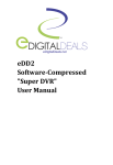
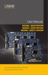
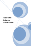
CCTV
Model: XUSB4DVR
4 Camera 25fps USB DVR Card
and Software
Before you begin
• Please unpack all boxes carefully and identify that all the parts are present.
• Do not cut the cables, this will void the warranty.
Model:
XUSB4DVR
4 Camera 25fps USB DVR Card
and Software
User Guide
2
XUSB4DVR User Guide
CONTENTS
1 INTRODUCTION ............................................................................................5
1.1 OVERVIEW ................................................................................................... 5
1.2 FEATURES...................................................................................................... 5
1.3 SYSTEM REQUIREMENTS ............................................................................. 6
1.4 SYSTEM SPECIFICATIONS ............................................................................ 6
2 HARDWARE INSTALLATION........................................................................ 8
2.1 VIDEO CAPTURE CARD HARDWARE............................................................. 8
2.1.1 XUSB4DVR Card Hardware.............................................................. 8
2.2 INSTALL VIDEO CAPTURE CARD DRIVER...................................................... 8
3 MAIN DISPLAY INTERFACE ....................................................................... 11
3.1 LOGIN........................................................................................................... 11
3.2 DISPLAY CONTROL PANEL ........................................................................... 11
3.2.1 Flip Pages ........................................................................................ 12
3.2.2 Auto Dwell display Mode................................................................. 12
3.2.3 Quick Switch ................................................................................... 12
3.3 RECORD ....................................................................................................... 12
3.3.1 Record Modes ................................................................................. 12
3.3.2 Recording Multiple Cameras............................................................ 12
3.3.3 Record Setup .................................................................................. 13
3.3.4 Record Status Panel ........................................................................ 14
3.3.5 Manual Record Mode ..................................................................... 14
3.3.6 Schedule Record Mode ................................................................... 14
3.3.7 Motion Detection Record Mode ...................................................... 14
3.3.8 Sensor Alarm Record Mode ............................................................ 15
3.3.9 Recycling Record ............................................................................. 15
4 SYSTEM SETUP .............................................................................................16
4.1 BASIC CONFIGURATION .............................................................................. 16
4.2 SCHEDULE CONFIGURATION........................................................................ 17
4.3 VIDEO CONFIGURATION .............................................................................. 17
4.4 MOTION DETECTION CONFIGURATION ....................................................... 18
4.4.1 Set Motion Detection Area............................................................... 18
4.4.2 Set Motion Detection Sensitivity ..................................................... 18
4.5 ALARM CONFIGURATION ............................................................................ 18
4.5.1 Alarm Triggering Conditions Configuration...................................... 18
4.5.2 Alarm Record .................................................................................. 19
4.5.3 Alarm Output Tab ............................................................................ 19
4.5.4 Auto Mail Function Tab.................................................................... 20
4.5.5 Emap Tab.......................................................................................... 20
4.6 PTZ CONTROL CONFIGURATION ................................................................. 20
3
XUSB4DVR User Guide
4.6.1 Protocol Setup ................................................................................ 20
4.6.2 Serial ports setup ............................................................................ 21
4.7 USERS CONFIGURATION .............................................................................. 21
4.7.1 Add User ........................................................................................ 21
4.7.2 Change User rights ......................................................................... 21
4.7.3 Delete User ..................................................................................... 22
4.8 E-MAP CONFIGURATION.............................................................................. 22
4.8.1 Edit a map ...................................................................................... 22
4.8.2 View the map.................................................................................... 23
5 P.T.Z CONTROL ............................................................................................ 24
6 RECORD SEARCH AND PLAYBACK ........................................................... 26
6.1 RECORD SEARCH ......................................................................................... 26
6.2 RECORD PLAYBACK AND CONTROL ............................................................ 26
6.3 OTHER FUNCTIONS ...................................................................................... 28
6.3.1 Record File Backup .......................................................................... 28
6.3.2 Delete Recorded Files ...................................................................... 28
6.3.3 Capture Pictures .............................................................................. 28
6.3.4 Image Zoom In / Out ....................................................................... 30
7 REMOTE SURVEILLANCE AND PLAYBACK .............................................. 31
7.1 REMOTE LIVE SURVEILLANCE ...................................................................... 31
7.1.1 Remote Surveillance Server Configuration ...................................... 31
7.1.2 Remote Surveillance Client-side Setup ........................................... 31
7.2 REMOTE PLAYBACK ..................................................................................... 34
7.2.1 Remote Playback Server Configuration ........................................... 34
7.2.2 Remote Playback Client-side Setup.................................................. 34
7.2.3 Remote Playback Configuration and Control Setup......................... 35
7.3 MOBILE SURVEILLANCE................................................................................ 37
7.3.1 Introduction to Mobile Surveillance ................................................ 37
7.3.2 Client Configuration of Windows Mobiles ...................................... 37
7.3.3 Client Configuration of Symbian 60 ............................................... 38
APPENDIX 1: FREQUENTLY ASKED QUESTIONS ....................................... 40
APPENDIX 1.1 ABOUT INSTALLATION ............................................................... 40
App 1.1.1 Cannot Install the SmartDVR Driver ....................................... 40
App 1.1.2 Why can’t I run SmartDVR in the Windows 2003 OS? .......... 40
App 1.1.3 ‘Unspecified error’ in the End of Installation .......................... 40
App 1.1.4 Cannot find XUSB4DVR in Device Manager ........................... 40
APPENDIX 1.2 HOW TO USE SMARTDVR............................................................ 41
App 1.2.1 What are the meanings of the indicator lights ....................... 41
App 1.2.2 How do the different record modes work? ............................ 41
App 1.2.3 How do I set Recycling Record mode on the system? ........... 41
4
XUSB4DVR User Guide
App 1.2.4 How to set the Auto Reboot function? .................................. 41
App 1.2.5 How to quickly use the Schedule Record function? ............... 41
App 1.2.6 What are the byte rates for different image qualities? .......... 41
App 1.2.7 The frame rate seems to be lower than what I set? .............. 42
App 1.2.8 Why I can’t select more channels to backup? ........................ 42
App 1.2.9 When should I select manual Gain Control? .......................... 42
APPENDIX 1.3 HOW TO USE THE NETWORK FUNCTION.................................... 42
App 1.3.1 How do I monitor on the client-side? .................................... 42
App 1.3.2 Why I can’t download the client-side software?.................... 42
App 1.3.3 Why can’t the server be configured at the clientside? .......... 42
App 1.3.4 Why I can’t see the images?.................................................. 42
App 1.3.5 What should I do if the Internet speed is quite slow? .......... 43
App 1.3.6 Why I can’t start WebCam server or RPB server? .................... 43
APPENDIX 1.4 OTHER QUESTIONS .................................................................... 43
App 1.4.1 Why doesn’t the computer display work, and why can’t I
access the window system? .................................................................... 43
App 1.4.2 Why I can’t find the recorded files? ........................................ 43
App 1.4.3 Why is the screen’s display is unstable with dithering and
water-wave images? ............................................................................... 43
App 1.4.4 Why is there a delay to playback, and why is it slow to
close and open the driver? ...................................................................... 44
App 1.4.5 Why can’t I playback?............................................................. 44
App 1.4.6 Why do I see some grey blocks on time progress bar area
when I playback? .................................................................................... 44
App 1.4.7 Why do I see some old record sections that can’t be covered
when I playback? ..................................................................................... 44
App 1.4.8 Precautions on changing system time .................................... 44
App 1.4.9 If the system time must be changed, make the following
preparations first: .................................................................................... 45
APPENDIX 1.5 SYSTEM QUESTIONS .................................................................. 45
App 1.5.1 How to use REPAIRDB to repair SmartDVR database? .......... 45
App 1.5.2 How to setup power options in the Microsoft VISTA system... 45
APPENDIX 2: QUICK START ..........................................................................
APPENDIX 2.1 TROUBLESHOOTING ..................................................................
App 2.1.1 When I open the SmartDVR application, it says ‘Can’t find
Card .........................................................................................................
App 2.1.2 How do I setup the Web Client to monitor from the
Internet? ..................................................................................................
46
46
46
47
APPENDIX 3 FUNCTION TREES...................................................................... 48
APPENDIX 4 NOTES ...................................................................................... 51
5
XUSB4DVR User Guide
1 INTRODUCTION
1.1 OVERVIEW
Thank you for choosing this Xvision USB Card and Software. The USB Card adopts MPEG4 compression
format, and allows up to 4 cameras to be recorded in real-time for live surveillance and playback, all
from a PC/laptop. The cameras can also be viewed and played back a remote PC on the same LAN or on
the Internet. In addition to this it can also synchronise the recording and transmission of audio from up
to 2 cameras.
This user guide will show you how to install the hardware and the SmartDVR 5.0 Software, and how to
setup the systems of this range of products. To maintain the stability of your PC DVR system, please
make sure you operate the product in accordance with this user guide.
1.2 FEATURES
The following are standard functions of the XUSB4DVR:
1. Schedule record mode
You can choose any period in a day to record and set up the record modes, i.e. sensor alarm
record, motion detection record, manual record, schedule record.
2. Motion detection mode
Motion detection areas are adjustable and you can assign up to 16 areas for detection for each
channel. You can also set the motion detection sensitivity for each channel. The system will only
begin to record only when motion in the detection area occurs, and it will stop recording after a
period of time which also is adjustable.
3. Recycling record mode
You can set the recording Storage Sequence for HDD partitions. The recording storage will
automatically jump to the next partition when it is full. If all the partitions are full and recycling
record mode is enabled, the old recorded data will be recycled and recorded over with new data.
You can also set a HDD Minimum Storage Alarm. Once the present storage space is less then the
minimum storage and recycling record mode is not enabled, the recording will automatically stop.
This means old data will never be recorded over.
4. P.T.Z control function
Supported by a number of decoders, you can control multiple speed domes and integrated
cameras. Controls include Pan, Tilt, Zoom, Focus and Iris Adjustment for P.T.Z devices. The system
also supports Preset Points and Auto Seek.
5. Management of Users
Different users can have different rights, user names and passwords, so as to ensure system is
secured against unauthorised users.
6. Multi-channel display
Supports Multi-channel Display mode, Full Screen display and Auto Dwell display.
6
XUSB4DVR User Guide
7. Real Time Recording
The USB Card can support up to 4 channels with a maximum frame rate of 25 fps.
8. Image Quality
Features MPEG4 compression, which greatly reduces HDD usage and supports 352x288 and
704x576 (PAL) standard resolutions. Also allows you to adjust the image colour for each channel,
including contrast, lightness, hue and saturation.
10. Powerful video playback functions
Including playback, pause, stop, fast-forward, single-frame play and image capture.
11. Support advanced search mode
Users can search by date/time, camera, record mode, or a combination of the three methods.
12. File Management
Supports recorded files backup, delete by date/time, camera.
13. Multiple Language support
Including Chinese (Traditional), English, German, Spanish, Portuguese and other customised
languages.
14. Remote Surveillance
You can view, playback and have PTZ Control from a remote PC on the same LAN or Internet
15. Alerts
Set buzzer and Email alerts with image snapshots when motion is detected
16. User-friendly graphical user interface
Simple user interface allows you to control the system with ease
17. Decrease file fragmentation
Features NTFS partition to decrease fragmented files
1.3 SYSTEM REQUIREMENTS
The following are the minimum system requirements for your PC:
Operating System:
Windows XP or Vista
CPU:
Pentium 4, 1.7GHz or above
Graphics:
Nvidia Geforce 2/ATI Rage 128 compatible or similar
RAM:
256MB
Direct X:
Version 9 or above
USB 2.0 Sockets required:
1
Please Note:
When the recording disk partition’s format is FAT32 and the system has run for a long time, the system will create
a lot of data fragments, that may result in the system running slowly. We recommend that you defragment your
hard disk every 10 to 30 days. We strongly suggest that recording disk partition uses NTFS format.
7
XUSB4DVR User Guide
1.4 SYSTEM SPECIFICATIONS
Format:
PAL/NTSC
Resolution:
352x288 / 704x576 (PAL)
Maximum Frame rate:
25 fps (PAL)
Screen set:
Resolution 1024x768, 16 bits or 32 bits
Compression code rate:
50kbps – 1.2Mbps
Data format:
MPEG4
8
XUSB4DVR User Guide
2 HARDWARE INSTALLATION
2.1 VIDEO CAPTURE CARD HARDWARE
2.1.1 XUSB4DVR Card Hardware
Audio Input (White)
Video Input (Yellow)
USB Connection
Fig 2.1 XUSB4DVR USB Video Capture Card
Please Note:
• Make sure that your PC USB interface is 2.0; the XUSB4DVR card can only support USB 2.0.
• Please follow the steps to safely remove the USB card:
Right click on the Taskbar > Stop device > pull out the USB card.
• Using this card with other USB device simultaneously may cause mean that PC is unable to identify the USB card.
• Do not insert two or more USB video capture cards simultaneously.
• Do not use with any other PCI video capture card simultaneously.
2.2 INSTALL VIDEO CAPTURE CARD DRIVER
Connect the USB plug on the XUSB4DVR to a
spare USB port on your laptop/PC and insert the
Software CD into the CD drive. Run ‘Setup.exe’
(located in ‘Install’ Folder), and the installation
interface will appear.
Select ‘Next to continue.
Fig 2.2 Welcome Page
9
XUSB4DVR User Guide
Select Video format and then click ‘Next’ to
continue.
For UK video format, select PAL
Fig 2.3 Select video format
After this process, the application package
SmartDVR will begin installation.
Select a suitable destination option, and click
‘Next’.
Fig 2.4 Select installation destination
Click ‘Next’ to continue.
Fig 2.5 Select Program Folder
10
XUSB4DVR User Guide
The Software will finish installing. Click ‘Finish’.
Now, restart the computer and start the
surveillance program.
Fig 2.6 Driver and application installation finished
You will see a shortcut will have been created on the desktop:
Fig 2.6.1 Shortcut of SmartDVR
Please Note:
When you install the driver software on a Microsoft VISTA system, you need select the option shown below when
you start the installation process. After this, follow the same steps as outlined previously for installing the software
on a Microsoft XP system.
If you cannot run the SmartDVR program, users
should restart the computer.
Fig 2.7 Install the Software on a VISTA system
11
XUSB4DVR User Guide
3 MAIN DISPLAY INTERFACE
When you run the SmartDVR program the Main Display interface will appear. The display will be locked
until you Login.
TIME & DATE
MAIN DISPLAY
CAMERA STATUS
ALARM OUT STATUS
LOGIN
E-MAP
SEARCH & PLAYBACK
CONFIGURATION
EXIT BUTTON
DISPLAY MODE
CONTROL PANEL
DISK SPACE
INDICATOR
PTZ CONTROL
Fig 3.1 SmartDVR Main Display Interface
3.1 LOGIN
Click
, and the Login window will appear. Input the user name and password. (The default user name
is ‘SYSTEM’ with no password). When you have logged in you will have access to the main interface. You
can change the system password and create new user names and passwords once you enter the system.
(Refer to Chapter 4.7 Users Configuration).
3.2 DISPLAY CONTROL PANEL
The Display Control Panel includes ‘Display Mode’ buttons, a Free Disk Space indicator, ‘Next Page’
button, ‘Auto Dwell’ button, 1 channel and 4 channel display buttons. Every button has its built-in
indicator light which will light on and off to indicate its working status.
Read below for the functions in the Display Control Panel.
12
XUSB4DVR User Guide
Fig 3.1 SmartDVR Main Display Interface
NEXT
PAGE
AUTO 1CH
DWELL
4CH
DISK SPACE
INDICATOR
3.2.1 Next Page
When in 1CH or 4CH display mode click the NEXT PAGE button to quickly switch to the next channel in
the display according to the mode.
3.2.2 Auto Dwell
See all the channels in sequence with the Auto Dwell display mode.
3.2.3 Quick Switch
If you are in 4CH display mode, by clicking any image, the display will quickly switch to the
corresponding single channel display mode. By clicking the single image again, it will return to the
former display mode.
3.3 RECORD
3.3.1 Record Modes
The XDVR4USB offers 4 kinds of record modes:
1. Schedule record mode (timer)
2. Manual record mode
3. Motion Detection record mode
4. Sensor Alarm record mode
Using Motion Detection record mode and Sensor Alarm record mode together is called Alarm Record
mode.
3.3.2 Recording Multiple cameras
When you record multiple cameras, every camera works separately and the recorded file are also saved
separately. The parameters, i.e. Camera ID, the Date and Time and the Record Mode used are all saved
together with the record file.
13
XUSB4DVR User Guide
3.3.3 Record Setup
Click on the
CONFIGURATION button to enter the System Setup page, then on the
BASIC
CONFIGURATION button and go to the ‘Record Panel’. It is in this section that you can set up all kinds of
necessary parameters for recording (see Chapter 4- System Setup).
Fig 3.5 Record Configuration Panel
• Time stamp
Select this option if you want the date / time of recording to appear on the recorded images.
• Switch
By selecting this options, you can turn on corresponding cameras. If there is no camera connected
to certain channels, don’t select the option to save unnecessary recording.
• Manual record
For continuously recording and saving the corresponding camera channel(s).
• Manual recording frame rate
Select the recording frame rate required for Manual Record mode.
• Schedule Record
For Schedule recording day or night of corresponding cameras. The times of recording can be set
within the Configuration page.
• Schedule Record Frame Rate
Select the recording frame rate required for Schedule Record mode.
• Motion Detection
For recording the corresponding camera(s) when motion is detected.
• Motion Record Frame Rate
Select the recording frame rate required for Motion Detection Record mode.
• Sensor Record Frame Rate
If sensors utilized to trigger recording, users can select record frame rate here.
• Camera Security
Users are divided into three standards: Normal user, Power user and Administrator. By selecting
this option, only administrators can see the corresponding camera channels.
• Record Quality
Select the image recording quality here.
• Audio In
The XUSB4DVR can support two channels of audio. You can choose up to two camera channels to
enable the audio recording from these corresponding camera(s).
Please Note: You can select more than one record mode.
14
XUSB4DVR User Guide
3.3.4 Record Status Panel
The meanings of the indicator lights in the Record
Status Panel are:
Normal State (no light, greyed out)
Manual Record mode (lime green light)
Schedule Record mode (bottle green light)
Motion Detection mode State (yellow light)
Sensor Alarm Record mode (red light)
Video Loss State (blue light)
Fig 3.6 Record Status Panel and Alarm Output Status Panel
The status panel is split in two sections. The top
indicator lights refer to the status of the CAMERAS
connected to the system.The second section refers to ALARM outputs. ie. when an indicator light turns
red in the second row, it means there is alarm output.
3.3.5 Manual Record Mode
Manual Record mode is the most commonly used record mode. If any special event happens, users can
select this mode and record continuously. In this mode, the indicator light in the Record Status Panel will
turn lime green.
Please Note: You can select a high frame rate for short periods of Manual recording, and select a low frame rate
for long periods of Schedule Record.
3.3.6 Schedule Record mode
Users can set a working schedule for all kinds of record modes in ‘Schedule Configuration’. The bottle
green light in the Record Status Panel will show the corresponding channel is in Schedule Record mode.
You can change the record mode to Manual Record at any time, and the bottle green light will change to
lime green. Please refer to chapter 4.2 for details.
3.3.7 Motion Detection Record Mode
This mode will enable the system to detect image changes and begin to record automatically by
activating the Motion Alarm Record mode.
For instance, if somebody opens the door, the system will detect changes in the image and begin to
record. Later, you can play back the recorded file and find out who opened door. When there is no
movement, the system will not record and that is helpful for saving system resources like hard drive
space, and convenient for searching for legitimate event files. When motion is detected, the indicator
light in the Record Status Panel will turn yellow.
Please Note: Users need to setup up to three things to enable Motion Detection Recording:
1. Select ‘Motion Detection’ for certain channels in ‘Basic Configuration’.
2. Configure the motion detection areas for certain channels in ‘Motion Detection Configuration’. Refer to chapter
4.3 for details.
3. Configure the working schedule for certain channels in ‘Schedule Configuration’. Refer to chapter 4.4 for details.
15
XUSB4DVR User Guide
3.3.7 Sensor Alarm Record Mode
Users can use sensors to trigger Sensor Alarm Record mode for corresponding channels. In this mode, the
Record Status indicator light in the ALARM section will turn red.
3.3.8 Recycling Record
You can enable the Recycling Record function and set the recording storage sequence for HDD partitions.
The recording storage will automatically jump to the next partition when it is full. If all the partitions are
full and Recycling Record mode has been enabled, the new data will overwrite the oldest recorded data
automatically. Please refer to chapter 4.1 for details.
You can also set the HDD Minimum Storage alarm. When the current storage space is less then the
minimum storage level set and Recycling Record mode has not been enabled, record will automatically
stop. Please refer to chapter 4.5 for details.
16
XUSB4DVR User Guide
4 SYSTEM SETUP
Click on the
CONFIGURATION button to enter the main System Setup page. The buttons shown at
the bottom of the screen are:
Basic Configuration
Schedule Configuration
Video Configuration
Motion Detection Configuration
Alarm Configuration
P.T.Z Configuration
User Configuration
Return
Fig 4.1 Basic Configuration
4.1 BASIC CONFIGURATION
Click
to enter the Basic Configuration page where you can setup the system or just use the defaults.
NOTE: You can Click
to return to the main display interface at any time. Below are the options
available in the Basic Configuration screen:
Dwell Interval
Set the dwell time between images for Auto
Dwell display mode. Select from dropdown.
Caption
There are four options to select for all the
channels. Select from dropdown.
• ‘None’ means no title;
• ‘ID’ means camera numbers, i.e. 1, 2, 3, 4
• ‘Name’ means camera names, i.e. Cam1,
Cam2 etc
Fig 4.2 Basic Configuration
• ‘ID/Name’ means both camera number and
camera name, i.e. 1/Cam1, 2/Cam2 etc
Resolution
There are two options, 352x288 and 704x576 for you to set the resolution for all the channels. The
video may have interlace lines if the you select 704x576, so you can select the
option to solve this problem. Note:De-Interlacing will use much more of the PC’s processing speed.
Storage Disk
The XUSB4DVR system shows all the available HDD partitions. You can select one or more of the
partitions that will be used in sequence from top to bottom. Check the Recycle option to allow the
17
XUSB4DVR User Guide
the system to automatically overwrite over old data if you have not set up the HDD Minimum
Storage alarm in the Motion Detection Configuration menu. Please refer to chapter 4.5 for details.
Internet Config Tab
Read more about this tab in chapter 7 Remote Surveillance and Playback.
PC Auto Reboot Tab
The windows system may become unstable
after a couple of days continuous operation.
You should reboot the PC/laptop regularly to
avoid the SmartDVR system from becoming
unstable. In the following area of the Basic
Fig 4.3 PC Auto Reboot tab
Configuration page, you can input your
computer’s user name and password in the relative boxes. You can select and set the interval by
day, which will guide the system to reboot automatically according to the setup. When restarting
the PC/laptop, the SmartDVR system will access the system automatically with details you enter.
4.2 SCHEDULE CONFIGURATION
Click
to enter the Schedule Configuration
page. The XUSB4DVR SmartDVR system offers
powerful schedule configuration options. Every
channel has three kinds of record modes:
Schedule Record, Motion Detection Record
and Sensor Alarm Record.
You can set schedules from Sunday to Saturday
separately for all of the three record modes.
Sensor alarm record mode has the highest priority
Fig 4.4 Schedule Configuration & Edit Schedule detail
among all record modes. To edit the schedule for a
channel, select the camera name within one of the
three record mode groups, select the colour bars on the right side, then select ‘Edit’. Alternatively you can
click ‘Add’ to add schedule for a certain channel (as shown in Fig 4.5). Click ‘Delete’ to delete schedule.
Click ‘Clear All’ to delete all the schedules of a certain channel.
4.3 VIDEO CONFIGURATION
Click
to enter the video configuration page.
Users can change the values of corresponding
settings for each camera by selecting it from the
drop down menu. You can adjust the Contrast,
Brightness, Hue and Saturation by moving the
scroll bars. To return to the default settings, click
‘Defaults’.
Fig 4.5 Video Configuration
18
XUSB4DVR User Guide
4.4 MOTION DETECTION CONFIGURATION
Click
page.
to enter Motion Detection Configuration
Definition of the setup items:
Sensitivity
Set motion detection sensitivity here.
Select all
Selects all of the area of the channel as the
detection area
Clear
Clears all the detection areas so you can
customise the detection area.
Fig 4.6 Motion Detection Configuration
4.4.1 Set Motion Detection Area
If you want to customise a detection area for a certain channel, first select the camera from the
dropdown menu, then select ‘Clear’. Then drag the cursor on the camera image over the area you want
set to have motion detection. You can select a maximum of 16 areas for each channel. The set area(s)
will be bounded by a green box. Click ‘Clear’, to clear all the selected areas of motion detection.
4.4.2 Set Motion Detection Sensitivity
Within the green-boxed areas, set the value for Motion Detection Sensitivity. The higher the number the
higher the sensitivity of detection.
4.5 ALARM CONFIGURATION
Click
to enter Alarm Configuration page.
4.5.1 Alarm Triggering Conditions
Configuration
The system can receive alarm both from local
device and network
1. LOCAL ALARM RECORD TRIGGERING
CONDITIONS CONFIGURATION
• Buzzer
Fig 4.7 Local place alarm triggering conditions
Users can select whether to turn on the
computer buzzer if an alarm gets triggered. Select value (seconds) from the dropdown menu.
• Full Screen Alarm
When an alarm is triggered (ie. when motion is detected), the corresponding camera channel
can be set to appear full screen to alert you. Select value (seconds) from the dropdown menu.
• Disk Shortage Alarm
If the HDD space available is less then the set value, the buzzer will beep if it has been enabled.
Select value (seconds) from the dropdown menu.
19
XUSB4DVR User Guide
• Pre-Alarm Record
You can set the length of pre-record time. Select value (seconds) from the dropdown menu.
• Motion Holding Time
You can set the length of time that the motion sensor must detect movement for before the
Motion Detection alarm is triggered. The system will only ‘alarm’ and start recording if
movement lasts for this period of time. Select value (seconds) from the dropdown menu.
2. ALARM OUTPUT TERMINAL IN LAN
Select ‘Remote Alarm’, and enter the area as
Fig 4.8 shows.
Click ‘Add’ to add alarm output terminals.
Find the terminal computer and click ‘OK’,
and you will see the name of the selected
terminal appear in the box as shown.
Fig 4.8 Alarm Output Terminal in LAN
Please Note: This function is only valid with LAN, but not with Internet connection.
4.5.2 Alarm Record
Every sensor can trigger multiple channels to record. For example, if users select CAM1, CAM4 and
CAM5 for Sensor2, then once the sensor is activated, CAM1, CAM4 and CAM5 will begin to record.
Users can also select the voltage, high and low, for alarm signals.
4.5.3 Alarm Output Tab
Click ‘Alarm Output’ tab to configure the Alarm
Outputs for your system
Video Loss
Users can select alarm output for this
option. For example, users select alarm_out1
and alarm_out3 and remote alarm for video
loss. Then video loss of any channel will
trigger alarm_out1, alarm_out3 to show red
light on the Alarm Output Status Panel (refer
to Fig 3.6 for reference), and the system will
Fig 4.9 Alarm Output Terminal in LAN
give out a related warning message to the
terminals in List of Alarm Output LAN Terminals
(refer to Fig 4.8)
Disk Alarm
If the HDD available space is less than the set value (see to Fig 4.9), it will trigger the chosen alarms.
Sensor
If users have sensors combined with certain alarm, when the sensors have been activated, then it
will trigger the selected output alarms. The XUSB4DVR card has a maximum of 4 sensors.
Motion
Users can set motion detection alarm output by different alarms and remote alarm. The XUSB4DVR
has a maximum of 4 motion alarms.
20
XUSB4DVR User Guide
4.5.4 Auto Mail Function Tab
Click ‘Auto Mail’ tab to enter the following area
to setup Auto Mail. This function will allow you
to receive automated emails to your inbox when
ever an alarm is triggered.
• Set receiver and sender’s E-mail, SMTP
server address and password.
• Include a Subject line for your reference
• Set the system to attach a still image
screen shot of the ‘alarmed’ channel by
selecting the ‘Attachment’ option.
• You can choose to write an introduction
to the Auto Mail in advanced, so the
receiver will know what happened.
To test the settings, click ‘Send Mail Test’.
If all settings are okay, message ‘Message Sent
Successfully’ will pop up. If some settings are
wrong, a pop-up window will appear showing
corresponding warning message.
Fig 4.10 Auto Mail Setup
Please Note:
• The address of receiver and sender can be the same
• For every alarm event, only one picture will be sent.
4.5.5 Emap Tab
Click ‘Emap’ tab to access the following functions:
• Auto Hide
Check the box and the the required value (in seconds) from the drop down menu.
• Emap Edit
Add cameras to the default map and save the map you created. (See section 4.8.1- Edit a map).
4.6 P.T.Z CONTROL CONFIGURATION
Click
to enter the PTZ Configuration panel.
4.6.1 Protocol Setup
Users can select different protocols, serial port
number for P.T.Z devices. (Refer to Fig 4.11). First
select the camera (1-4) and then select values for
Protocol, Serial Port, and Address from the
dropdown menus.
Fig 4.11 PTZ Configuration panel
21
XUSB4DVR User Guide
4.6.2 Serial ports setup
First enable the P.T.Z control function of a certain
camera and select a port number in P.T.Z Protocol
Setup, and then setup the corresponding
parameters using the dropdown menus to select
the required values.
Port: Set the PTZ port number.
Baud Rate: Default value is 9600.
Data bits: Default value is 8.
Parity: Default is None.
Stop Bits: Default value is 1.
Fig 4.12 Serial Port setup
Please Note:
Ensure you first look into the P.T.Z device and get the Baud Rate, Protocol, and Address, then set their values
accordingly.
4.7 USERS CONFIGURATION
Click
Fig 4.13 ‘Add User’ in
User Configuration
to access the User Configuration page.
After installing the SmartDVR system, an
Administrator user with the default user name
‘SYSTEM’ and no password will be created. Use
this user name to login to the system and ‘Add’,
‘Edit’ and/or ‘Delete’ users rights.
4.7.1 Add User
Click ‘Add’ in User Configuration (refer to Fig 4.13).
Input the details shown and then click ’OK’.
4.7.2 Change User rights
Select a user in User Configuration area and click
‘Edit’ to enter Edit User area (refer to Fig 4.14).
Users can edit user’s password and rights here, but
not the user name.
Fig 4.14 ‘Change User
Rights’ in User
Configuration
Please Note: The system offers three kinds of rights:
• Administrator: has the highest rights to change all the settings and playback.
• Power user: cannot access Basic Configuration and change settings, but has all the other rights of Administrator.
• Normal: this kind of user can only access SmartDVR main display interface (refer to Fig 3.1)
Administrators can change Power and Normal users’ rights, but can’t change other administrators’ rights.
22
XUSB4DVR User Guide
4.7.3 Delete User
Select the user name in User Configuration (refer to
Fig 4.13), and click ‘Delete’. Confirm by clicking ‘OK’,
as shown in Fig 4.15.
Fig 4.15 Delete user
confirmation
4.8 E-MAP CONFIGURATION
Click
on the Main Display interface to enter
the E-map page (Fig 4.16). You must have already
created a map in order to access this feature,
otherwise you will get an error message ‘No map
exists!’.
A E-map is used to show the full geographic range
covered by the whole monitoring system in the
form of graphical map. The E-map function
features simple operation and gives you a direct
display of the status of the cameras connected to
the system. It is generally graded or tiered in the
form of a tree diagram.
Fig 4.16 E-map
4.8.1 Edit a map
Save your map of your premises on your PC/laptop
in the ‘Pictures’ folder located in ‘My computer’ as
a bmp or jpg. When in the E-map page, right click
the mouse on the default E-map image and select
‘Load Picture’. Locate the image you saved earlier
and select the file name. The new map will be
displayed in the E-map interface.
Fig 4.17 Selecting a new map
Draw icons of cameras to the corresponding position on the map.
You can add a maximum of 16 cameras in total. To edit a camera image, right click on the default image
and select ‘Change Icon’ to select another camera image. To delete a camera, right click on the camera
and select ‘Delete’ to remove it from the map. After editing, right click on the map and select ‘Save Map’
to save the current map.
You can tier maps to organise the E-map function. For example, you can have a ‘first tier’ map which
would show a map of an entire floor of a building. The ‘second tier’ maps could be specific to certain
rooms on that floor, giving a more detailed plan of where your cameras are located.
A grey map icon can be added to the corresponding position in the ‘first tier’ map. To create a sub-map
of the current map, right click the gray map icon on the left of the control panel and select ‘Open’ to
build a new map. You can also click on any blue map icon on the left by right clicking and selecting
‘Rename’ to change name of the map. Select ‘Close’ to cancel a map.
23
XUSB4DVR User Guide
4.8.2 View the map
Click
to enter E-map, where you can view the
distribution of all the cameras in the map, as Fig
4.16 shows.
When a camera channel alarms, ie. if motion is
detected, the corresponding camera icon will flash
yellow to indicate an alarm signal.
If you select ‘Auto show’, the alarming camera’s
image will pop out automatically as a mini-screen
and show the live image so you can view the
motion detected, as Fig 4.18 shows.
Fig 4.18 Auto show on Alarm
If ‘Auto Show’ is not selected, you can right click
the camera head to show the live camera image.
Further options are available in the Basic Configuration > Alarm menu, in the E-map Tab. Here you can
select if you wish the E-map alarm screen to ‘Auto-hide’ after the live image pops up on screen and the
holding time the E-map stays on screen when an alarm is triggered.
Please Note:
• E-map only supports three tier levels
• When loading a customised map, the image will be enlarged or shortened proportionally to fit the standard size
of the E-map frame (833x678 pixels)
• If ‘Auto Close’ is set, the pop up screen which opens on an Alarm triggering will close automatically after the
‘Holding Time’ is over and there is no other activity. ‘Auto Close’ is invalid when the E-map is opened manually.
• The default map in the E-map is a demonstration map, and you can use your own map by saving it as a JPEG or
BMP file.
24
XUSB4DVR User Guide
5 PTZ CONTROL
Click
in the Main Display interface to enter
the PTZ Control interface. (Refer to Fig 5.1)
Users can control P.T.Z devices by the function
buttons on the right side, as shown.
In the lower bar, there are five function buttons,
i.e. upward button, downward button, leftward
button, rightward button and stop button. The
other buttons are Focus buttons (+ and -), Zoom
buttons (+ and -), Iris buttons (+ and -). Click ‘+’
and ‘-’ to increase and decrease the corresponding
values.
When you need to utilize P.T.Z control, first enter
P.T.Z Control Interface (refer to Fig 5.1), and click
the corresponding channel (users can see a red
frame around the channel), then users can begin
to control the P.T.Z control enabled camera.
Fig 5.1 P.T.Z Control interface and buttons panel
Please Note:
After pressing left mouse button on any function button in P.T.Z Control Function Buttons Panel, PTZ device will
start moving, when you releases it, the PTZ device will stop moving.
You can also can select different Pan speed, Tilt
speed, Focus speed and Zoom speed for P.T.Z
devices. Click on the
button to adjust the
following:
Pan Speed
Set horizontal rotating speed
Tilt Speed
Set vertical rotating speed
Focus Speed
Set camera focus speed
Zoom Speed
Set zoom in/ zoom out speed
Click on the
button and a pop-up window will
appear; you can choose different preset or group
settings.
Fig 5.2 Speed adjustment
Fig 5.3 Preset and
group select
25
XUSB4DVR User Guide
Click on the
button to set a Preset point and
change Preset point name. Every Group includes
multiple Preset points. In case users select preset1,
preset2 and preset3 for group1, preset1, preset2 and
preset3 will be automatically accessed in sequence
after users select group1 for auto scout.
Click on the
button and a popup
window as following will appear as shown in
Fig 5.5.
Dwell
Set the dwell time of a page here.
Fig 5.4 Preset
Fig 5.5 Group configuration
26
XUSB4DVR User Guide
6 RECORD, SEARCH & PLAYBACK
Click
in the SmartDVR Main Display Interface
(refer to Fig 6.1) to access to the following area:
This interface is divided into 4 parts, i.e. Record
Search area, Record Playback area, Record Play
area and other functions area.
Press
to return to the Live Display status.
Fig 6.1 Search & Playback Interface
6.1 RECORD SEARCH
A, B and C marks the areas of three search
methods:
Fig 6.2 Record Search area
Search by Date
Record Time display
Search original files
A: Search by date (ranges from Jan 1st, 1971
till now)
B: Search in backup file and original file
C: Search by record mode. This is useful when
you want to look through some important
events.
You can select one or all three searching
methods above to search for needed record files.
Search backup files
Search Manual Recordings
Search Scheduled Recordings
Search Motion Recordings
Search Sensor Alarm
Recordings
6.2 RECORD PLAYBACK AND CONTROL
The functions in the Search & Playback interface are:
Play / Pause
Stop
Play backwards. This button is valid when playing back by single channel
Previous Section. This button is valid when playing back by single channel
Next Section. This button is valid when playing back by single channel
Previous Frame. This button is valid when playing back by single channel playback pause mode
27
XUSB4DVR User Guide
Next Frame. This button is valid when playing back by single channel playback pause mode
Users can select suitable play speed in the
area as below:
Fig 6.3 Play Speed Controller
The following area shows the record files of different channels:
Fig 6.4 Recorded Files browser
The upper bar shows the hours in a whole day. Click the bar, and it will be magnified 10 times, so you
can see the time marks in details. When searching for a certain section of the file, you can draw the bar
to the area which most likely contains the needed section. If necessary, click the bar once to see the
magnified time marks for precise search. Click again to return to normal view.
The left side shows the available channels. When a certain channel has been selected for playback, the
background colour will be highlighted and a tick sign will appear beside the channel name, otherwise it
will appear dark grey.
Bars under the picture view area give details of the recorded files. The different colours of the bar indicates
the different kind of record modes of the files. The following are the definitions of the colour bars:
Click
Manual Record Events
Schedule Record Events
Motion Detection Record
Events Sensor Alarm Record Events
to play selected record files.
The system offers 1 Channel and 4 Channel
playback modes. The playback control area shows
the playback modes as shown in Fig 6.5. The
system’s default playback mode is one channel.
Fig 6.5 Multiple Channels
Playback Control
If you need to change to other channels, click
and the Channel Configuration window will
appear. You can select one channel from all the
available channels for playback.
If you need to play back 4 channels at the same
time, then click
to switch to 4 channel mode.
Fig 6.6 Channel Configuration Window for 1 Channel
Playback Mode
Please Note: You can click any channel and magnify it to see it in single channel mode. Click again to return to 4
channel playback mode.
28
XUSB4DVR User Guide
6.3 OTHER FUNCTIONS
6.3.1 Record File Backup
Click
to enter the Backup menu.
You can select corresponding cameras and copy
the record files to another path in this area. This is
the file backup function of the system. The
interface is divided into four areas:
A: Camera Selection Area
B: Time and Date Selection Area
C: Operation Area
D: Information Area
Fig 6.7 Recorded files Backup
• In area A, you can select one or more cameras;
• In area B, you can set start time/date and end time/date, to backup the recorded files in the time
interval by channels selected in area A;
• In area C users can set backup path
• Click ‘Start’ to backup files.
6.3.2 Delete Recorded Files
Click
to enter the Delete Recorded Files menu.
First select the channel on the left side, and then
select start time/date and end time/date of the
record files you wish to delete. Click ‘Start’ to
delete files.
Fig 6.8 Delete Recorded Files
6.3.3 Capture Pictures
The definitions of the function buttons are as below:
Capture Snapshot
Print Setup
Print Snapshot
Please Note: You can only capture a Snapshot of playback footage when you are in single channel playback mode
and have PAUSED the video. (refer to Fig6.2)
29
XUSB4DVR User Guide
When in single channel playback pause mode, the
Colour Control Panel (Fig 6.7) will appear
automatically, in which you can make colour
adjustments for the current channel, including
brightness, contrast, saturation and hue. Press
‘Default’ to recover to the original settings.
Fig 6.9 Colour Control Panel
When in single channel pause mode, click and to
enter the Snapshot menu. You can capture
multiple images in sequence by selecting the
number of frames to capture.
Select the path you wish to save the snapshot
image to and click ‘Save’ to save the picture.
Fig 6.10 Snapshot
You can also print the images that have been
captured.
Click
to enter the Print Setup menu.
Use this area to assign a printer to the application
and configure your printer settings.
Fig 6.11 Print Setup
You can see a print preview of the snapshot before
you print. Select
and to go into the Print
menu.
• Select ‘Position’ and use the ‘+’ and ‘-’ buttons
to move the picture up, down, left and right.
• Select ‘Size’ and use the ‘+’ and ‘-’ buttons to
zoom in and out the image.
• Select ‘Title’ and/or ‘Time’ to include the
camera name and recording time in the print.
• Press ‘Default’ to return to the original setting.
• Press ‘Print’ to print the image.
Fig 6.12 Print Preview
30
XUSB4DVR User Guide
6.3.4 Image Zoom In / Out
When in single channel playback state, the zoom
control icons will appear.
Zoom Out: Select and click on the channel
to zoom out the image. By clicking
continuously, the image will be zoomed
out continuously.
Zoom In: Select and click on the channel
to zoom in on the image. By clicking
continuously, the image will be zoomed
in continuously.
Default size: Click and recover the
original size.
Fig 6.13 Original Size
See Fig 6.13 to Fig 6.15 for examples of Image
Zooming.
Fig 6.14 Zoomed Out
Fig 6.15 Zoomed In
31
XUSB4DVR User Guide
7 REMOTE SURVEILLANCE & PLAYBACK
7.1 REMOTE LIVE SURVEILLANCE
The XUSB4DVR surveillance system supports Remote Surveillance through LAN, Internet and Intranet.
Simply enable the web cam function of the system on a computer which is connected to Internet, and
the computer system will become an Internet web cam server. To view remotely on any other computer
that connects to Internet or the same LAN network, simply input the SmartDVR server address in IE
browser to view high quality real time image from the server and also control any connected P.T.Z
devices.
7.1.1 Remote Surveillance Server
Configuration
You should firstly enable the Web Camera Services
in Basic Configuration (refer to Fig 4.1) and set
other settings as below:
HTTP Port
Web service & download service port,
default value is 80
Data Port
Data transmission port, default value is 1159
Command Port
Control command port, default value is 1259
Picture Quality
Default value is higher
Fig 7.1 Web Cam Server configuration
7.1.2 Remote Surveillance Client-side Setup
On the client-side, you should first install the
WebCam program. This can be accessed by
entering the IP address of your PC or laptop into
Internet Explorer (see note below).
This page will appear:
Live Surveillance
This option is for users to see live camera
images remotely.
Remote Playback
This option is for users to play back recorded
files.
Fig 7.2 Remote surveillance and playback services selection
Please Note: In case the HTTP port setting is not 80, (80 is the default setting) when you input the server IP
address, you should add the port number after the IP address. For example, the server’s IP address is
211.148.96.234, and the port number is 81, then you should input http://211.148.96.234:81.
32
XUSB4DVR User Guide
Select ‘Live Surveillance’, and click ‘OK’ to install
Remote Surveillance client-side program as below.
In the next section, we will learn more about
Remote Playback.
When connecting to the server for the first time,
the following window will appear. See Fig 7.3.
Please Note: If users have already installed the
client-side program before inputting the server
address in the IE browser, the system will
automatically skip the installation.
Fig 7.3 Inquiry for installing WebCam downloading component
Follow the on screen installation steps to
download and install WebCam, the client-side
program for viewing live images.
After initialisation has completed, WebCam will
be installed automatically.
Fig 7.4 WebCam installation
You can choose path by clicking ‘Browse’. Click
‘Next’ to continue:
Fig 7.5 Default install path
33
XUSB4DVR User Guide
Click ‘Next’ after inputting the folder name or
select the default name, and then press ‘Finish’ to
finish installation.
Fig 7.6 Register program folder name
Then the WebCam main interface will appear.
Click
and input User Name and Password, as
shown in Fig 7.7.
Please Note: The default User name is SYSTEM
without password. You can set user name and
password on the server end (refer to Chapter 4.7).
Click ‘Options’ and enter the advanced setting
area. You can modify default Server IP, Data Port
and Command Port.
Fig 7.7 Main Interface and Login
After logging in the server, you will get the first
channel video from server, and you can adjust
screen mode just like SmartDVR, Fig 7.8 shows the
WebCam Surveillance mode interface.
The Status Panel and PTZ controls are all same as
SmartDVR, refer to previous chapters to learn
more.
Fig 7.8 WebCam Surveillance screen
34
XUSB4DVR User Guide
7.2 REMOTE PLAYBACK
7.2.1 Remote Playback Server
Configuration
For the remote playback function, you should first
enable WebCam Service and Remote Playback
Service in Basic Configuration (refer to Fig 4.1
and Fig 7.9).
RPB Port
The default value is 13551
Fig 7.9 Remote Playback Service configuration
Please Note: Uses can enable remote playback service without running the SmartDVR. Just enter the installation
folder of SmartDVR, and activate MediaServer, users can also enable the RPB service.
Once the remote playback service has been
enabled, there will be an icon on the taskbar to
remind users the service has been activated.
Fig7.10 Remote
Playback Service
activated
7.2.2 Remote Playback Client-side Setup
You should also first download and install
playback program. To do this, input the PC or
laptop’s IP address in IE browser, select ‘Remote
playback’ and click ‘OK’,
Please Note: If users have already installed the
client-side program before inputting the IP address
in the IE browser, the system will automatically
skip the installation.
Fig 7.11 Remote surveillance and playback services selection
For details on the installation process refer to
Chapter 7.1.2.
After installation, the playback client-side main
interface will appear as shown in Fig 7.12.
Fig 7.12 Remote playback client-side main interface
35
XUSB4DVR User Guide
The functions in the Remote Playback interface are:
Log in
Setup
Exit
Play
Pause
Begin / Stop record
Slow down playing speed
Accelerate playing speed
Play at the original speed
7.2.3 Remote Playback Configuration and
Control Setup
Before logging in the server, first click
to make
the necessary Network and Recording path
settings.
Fig 7.13 Client-side configuration
Log in Remote Playback System by clicking
after finishing the configurations and input the
right user name and password to enter the remote
playback main interface.
Please Note: The default User name is SYSTEM
without password. You can set user name and
password on the server end (refer to Chapter 4.7).
Fig 7.14 Client-side configuration
After you log into the system, the setup and login
buttons will be disabled.
Fig 7.15 Remote playback main interface
36
XUSB4DVR User Guide
Click on first icon on the bottom left of the screen,
next to where the date and time information is
shown. Select the time period you wish to
playback, then click ‘OK’ to save the setting and
return to the main interface. The selected time /
date will appear in the left bottom of the screen.
Click ‘Cancel’ to cancel the setting.
Click on
to make the Event Browser window
appear. This will give you a detailed log of events
that have occurred per camera, allowing you to
select a recording by event rather than just by time
and date.
Fig 7.16 Select date/time period for playback
Click
to play the recorded files. Press
to pause. You can use the time bar to adjust the
time period that is playing, marked as (a) on Fig
7.17. Use the buttons marked as (b) on Fig 7.17, to
control the play speed.
(a)
(b)
Fig 7.17 Time Control & Play Speed Control
Click
to begin to recording remotely. The icon will change to
. Click it again and stop
recording. You can select the Save Path and Compression format before logging in the system, see
Chapter 7.2.3.
37
XUSB4DVR User Guide
7.3 MOBILE SURVEILLANCE
7.3.1 Introduction to Mobile Surveillance
In SmartDVR system, the mobile surveillance can be setup by connecting a mobile phone to the system.
The function is supported by Windows Mobile system and Symbian Series 60 Developer Platform 2.0
Intelligent Mobile Phone system. So far, the types of phones on which the function has been tested are in
the table below.
Nokia N95
S60
OS9.2
Other brands/models are being added regularly, see www.x-vision.co.uk for latest details
7.3.2 Client Configuration of Windows
Mobiles
The Server Configuration on SmartDVR needs to be
set before the function on phone is activated.
Please refer to Section 7.1 ‘Remote Live
Surveillance’. First activate the Network Access on
the mobile phone and then run ‘Internet Explorer’
after the Server Configuration is complete. Input
the server’s address and the connection will be
established as shown here.
Fig 7.18 Mobile
connected to the server
38
XUSB4DVR User Guide
Click ‘PCam v1.0.6.5291’.
Fig 7.19 Downloading
dialog box
A dialog box will pop up as shown in Fig 7.19.
Click “Yes” to start installing.
PCam will be opened after the download is
finished.
Fig 7.20 Main Interface
of PCam
Input the server’s address, username and password
respectively in the fields ‘Server’, ‘User’ and
‘Password’ and then click ‘Go’ to login to the
server. Successful login information will appear if
the server address, username and password are all
correct.
Channel 1 is the default displaying channel after
successful login. You can change the displayed
channel by selecting the channel in drop down
‘Channel’ menu.
Fig 7.21 Selecting
channel
Click ‘Stop’ at any time to disconnect the
communication with the server.
7.3.3 Client Configuration of Symbian 60
The Server Configuration on SmartDVR needs to be
set before the function on phone is activated.
Please refer to Section 7.1 ‘Remote Live
Surveillance’. First activate the Network Access on
the mobile phone and then run ‘Internet Explorer’
after the Server Configuration is complete.
Input the server address in a new-built bookmark.
Click this bookmark to connect to the server.
Fig 7.22 Open Web
Browser & build new
bookmark
39
XUSB4DVR User Guide
Click ‘install package’ to start downloading. A
confirmation pop up window will appear after
downloading is finished. Click ‘Yes’.
The system will then ask you whether to install the
‘SCam’ application. Click ‘Yes’.
Fig 7.23 Connect to the Server & Installation popup
A SCam shortcut icon appears on the
desktop after the installation has been done.
Fig 7.24 SCam shortcut
icon in system menu
Run SCam by clicking the icon.
Enter the main menu by clicking ‘Options’. Click
‘Settings’ to set the login information.
Fig 7.25 Selecting
channel
Input the server’s address, username and password
respectively in the fields ‘Server’, ‘Username’ and
‘Password’ and then click ‘OK’.
Now go back to ‘Options’ then click ‘Login’ to
establish communication with server.
Fig 7.26 Configure Login information & successful login
40
XUSB4DVR User Guide
APPENDIX 1
Frequently Asked Questions
APPENDIX 1.1 ABOUT INSTALLATION
Appendix 1.1.1 Cannot install the SmartDVR Driver
Possible causes:
1. XUSB4DVR has not been plugged in properly. Please unplug the card and install it again or change
to another USB slot.
2. Not compatible with PC hardware.
Appendix 1.1.2 Why can’t I run SmartDVR in the Windows 2003 Operating System?
Enable Hardware Acceleration and DirectX Acceleration:
• Hardware Acceleration
Click mouse’s button, follow the path:
Properties > Setting > Advanced > Trouble Shooting, and drag the acceleration bar to ‘Full’, click
‘OK’ to save the modification.
• DirectX Acceleration: click Start > Run, input “dxdiag” and click ‘Enter’. Select ‘Display’ option in
the pop-up window of ‘DirectX Tools’ and click the three buttons ‘DirectDraw>Direct3D and AGP
Texture’.
Appendix 1.1.3 ‘Unspecified error’ in the End of Installation
Possible causes:
1. On English version Window XP system, by using driver below SmartDVR 3.0.2, the unspecified
error will appear, as the databases are not compatible.
2. Microsoft Windows system database has been destroyed. Reinstall windows system or try to install
SmartDVR driver above SmartDVR3.1.1 to solve the problem.
3. Relative Windows support files has lost or been destroyed, reinstall window system, or try to install
SmartDVR driver above SmartDVR3.1.1 to solve the problem.
Appendix 1.1.4 Cannot find XUSB4DVR in Device Manager
Possible causes
1. Windows system error. Restart computer.
2. XUSB4DVR card error. Contact local distributor.
3. Install SmartDVR
41
XUSB4DVR User Guide
APPENDIX 1.2 HOW TO USE SMARTDVR
Appendix 1.2.1 What are the meanings of the indicator lights?
Refer to Chapter 3.3.3 and Fig 3.6 to learn more.
Appendix 1.2.2 How do the different record modes work?
Users can set more than one record mode in Record setup, but there is only one valid record mode for a
certain period. The priority order of the record modes is: Sensor Alarm Record > Motion Detection
Record > Manual Record > Schedule Record
Appendix 1.2.3 How do I set Recycling Record mode on the system?
Select ‘Recycle’ in basic configuration, refer to Fig4.1. You can select multiple HDD partitions to save
record files. The system will not re-write pre-recorded files until all the partitions’ available storage
spaces are less than 100MB.
If you have not enable recycling record mode and the partition’s storage spaces are less than 100MB, the
alarm will ring and the HDD usage indicator will turn red.
Please Note: It is recommended that you install SmartDVR into the partition installed with windows system
(normally C:), and save record files in HDD partition D.
Appendix 1.2.4 How do I set the Auto Reboot function?
If the Microsoft Windows system continuously runs for a couple of days, the system may become
unstable, therefore it is suggested to restart the computer every few of days. In the Basic Configuration
(refer to Fig 4.1, page 16), input Windows user name and password (Note: Not SmartDVR user name and
password), and set the time interval. The Windows system will automatically restart according to
the set time.
In case the Windows system closes down unexpectedly, i.e. during a power cut, when the computer
reboots next time, the SmartDVR system will automatically restart, and keep the settings as before.
Please Note: You don’t have to enable the auto reboot function, but it is suggested to input the Windows user
name and password in the relative area, so in unexpected systems failures occur, you do not have to input
Windows and SmartDVR user names and passwords.
Appendix 1.2.5 How do I quickly use the Schedule Record function?
Press the ‘Shift’ or ‘Ctrl’ key, and drag the cursor over the corresponding areas to make schedules for
multiple channels.
Appendix 1.2.6 What are the byte rates for different image qualities?
When on PAL system and the frame rate is 25 fps (across all cameras), bit rate for the highest image
quality is about 120K Byte/s, and for the lowest image quality is about 30K Byte/s.
42
XUSB4DVR User Guide
Appendix 1.2.7 The frame rate seems to be lower than what I set?
There is frame loss during image switching therefore the real record frame rate is relatively lower than
the theoretic value.
Appendix 1.2.8 Why I can’t select more channels to backup?
Drag the mouse in the channel selection area, or utilize Shift and Ctrl key to select multiple channels.
Appendix 1.2.9 When should I select manual Gain Control?
If the video signal is seriously decreasing, and the colour images turn to black and white, using manual
gain control maybe helpful.
APPENDIX 1.3 HOW TO USE THE NETWORK FUNCTIONS
Appendix 1.3.1 How do I monitor on the client-side?
First enable ‘Web Cameras service’ in basic configuration (refer to Fig 4.1). Input the server Internet
address in IE browser on the client-side, and the necessary Web Cam driver will be downloaded
automatically, then install the driver. After accessing the Web Cam Main Interface, click ‘login’ and input
the User Name and Password to log in the system. (Refer to Chapter 7 to learn more).
Appendix 1.3.2 Why I can’t download the client-side software?
Possible causes:
1. The client-side computer has not been properly connected to Internet or LAN.
2. The server-end has not enabled ‘web cameras service’
3. The default HTTP port is 80. It may be conflict with other Web servers, for example IIS. If this is the
case, change to another port.
4. Windows XP SP2 blocks the OCX download. You should enable ‘Internet Option > Security Settings
> Download unsigned ActiveX controls’.
Appendix 1.3.3 Why can’t the server be configured at the client-side?
Possible causes:
1. It can not be configured at the client-side when the server is being configured at the server-end.
2. Only the last configuration is valid if different server configurations are deployed simultaneously.
Appendix 1.3.4 Why I can’t see the images?
Possible causes:
1.
2.
3.
4.
5.
The VGA card is too outdated.
DirectDraw has not been installed
SmartDVR cannot run in Window 98 system.
A data port or command port is conflicting with other network services.
The user is connected to Internet through LAN, and the network administrator has not enabled the
corresponding data port or command port.
43
XUSB4DVR User Guide
6. The client-side has installed firewall software that may prevent video transmission.
7. MPEG4 codec has not been installed properly, please download the new version of WebCam.
8. Poor network connection or speed.
Appendix 1.3.5 What should I do if the Internet speed is quite slow?
The more channels opened, the slower the video transmission speed is, therefore try to use one channel
display mode when the network speed is slow.
Please Note: There may be some surplus channels that have no video input. Switching off the channels will help
to improve transmission speed. (Refer to Basic Configuration about switching on/off channels.)
Appendix 1.3.6 Why I can’t start WebCam server or RPB server?
Possible causes:
1. Other software applications are using these ports. If so, please change WebCam ports
configuration or stop conflicting applications.
APPENDIX 1.4 OTHER QUESTIONS
Appendix 1.4.1 Why doesn’t the computer display work, and why can’t I access the
window system?
The capture card may not be well installed. Unplug the card and try it again.
Please Note: Unplug the power plug of the computer, so as to avoid damaging the motherboard chip set.
Appendix 1.4.2 Why I can’t find the recorded files?
The main cause of this would be there was not enough HDD space and the files were not recorded.
Appendix 1.4.3 Why is the screen’s display unstable with dithering and water-wave
images?
Possible causes:
1. Camera’s power input is not high enough.
2. There is external electromagnetic disturbance, or electrostatic disturbance of camera BNC
connector (It is suggested to connect ground wire to the connector).
3. You have not installed necessary VGA driver.
4. VGA card problem. Try reinstalling the VGA card, or changing to another VGA card.
44
XUSB4DVR User Guide
Appendix 1.4.4 Why is there a delay to playback, and why is it slow when I close and
open the driver?
Possible causes:
1. Windows system problem. Try to reboot the computer.
2. There are too many recorded files or too many fragments on the HDD, therefore it takes time to
search for the files. You need to delete the files that you do not need, or run disk defragmenter
now.
3. XUSB4DVR card problem.
4. Computer hardware system is too outdated.
Appendix 1.4.5 Why I can’t playback?
Possible causes:
1. The Windows media player may have been damaged, or the decoder has not been installed
properly. It is suggested you reinstall the relative software system.
2. Computer problem, recorded files have been damaged. It is suggested to fix these files using
SuperAVIFix program.
Appendix 1.4.6 Why do I see some grey blocks on time progress bar area when I
playback?
Possible causes:
1. These recorded files may have been deleted.
2. SmartDVR has deleted recorded file when recycle option has been chosen.
3. Recorded files can not be opened because they are being recorded.
Appendix 1.4.7 Why do I see some old recorded sections that can’t be covered when I
playback?
Possible causes:
1.
2.
3.
4.
You have selected a disk partition different from the current one.
These recorded files are being played back when covering it.
Database of recorded log was damaged.
You have installed SmartDVR in different directory.
Appendix 1.4.8 Precautions on changing system time
1. The SmartDVR system provides the retrieving mechanism for video files, which must take the
system time as a retrieving reference. To change the computer time after installation will create
a high risk of incorrect time reference which can cause directory errors in recording search in order
to avoid this, note the following points.
2. Before SmartDVR is used, it must be confirmed whether the current computer time is correct.
3. Deactivate the computer’s auto updating of time
4. Make sure the main board of the computer is functioning normally
45
XUSB4DVR User Guide
Appendix 1.4.9 If the system time must be changed, make the following preparations
first:
1. If new time is later than current computer time (for example, change 2006/01/01 00:00:00 (current
system time) to 2007/01/01 00:00:00 (target time)), the change can be made instantly;
2. If new time is before the current computer time (for example, change 2007/01/01 00:00:00
(current system time) to 2006/01/01 00:00:00 (target time)), first stop the video recording, backup
all video data. Turn off SmartDVR, change computer time and then re-start SmartDVR.
APPENDIX 1.5 SYSTEM QUESTIONS
Appendix 1.5.1 How do I use REPAIRDB to repair SmartDVR database?
Enter the installation directory of SmartDVR: C:\ProgramFiles\SmartDVR\SmartDVR, open the
REPAIRDB.EXE file. The user name and password need to be entered, (User name is ‘SYSTEM’ and there is
no password). After entering, select database to repair.
Appendix 1.5.2 How to setup power options in the Microsoft VISTA system
After installing the VISTA system, go to Start > Control Panel > System and Maintenance. Select ‘Power’
option in the System and Maintenance window. Lastly, select the ‘High Performance Change Plan Setting’
option.
Please Note: The digital video capture cards support Intel CPU on VISTA edition.
46
XUSB4DVR User Guide
APPENDIX 2
Quick Start
Before installing the XUSB4DVR card, check PC requirements:
• Windows XP or Vista
• Pentium 4, 1.7GHz
• Nvidia GeForce2/ ATI Rage 128 compatible or similar
• 256 MB RAM
• DirectX 9.0 minimum
• 1x USB 2.0 socket required
INSTALLATION INSTRUCTIONS
1.
2.
3.
4.
5.
6.
7.
8.
9.
Insert the PCI card. (But DO NOT connect the Camera yet.)
Boot up to windows
Windows will come up with Hardware wizard. Just click CANCEL
Put the installation CD in and open up SmartDVR folder run the ‘setup file’
Follow the steps in Windows XP, it will come up with a message saying ‘This program has not
passed windows logo testing. Click ‘Continued anyway’"
Reboot computer once it completed.
Once you restart, there will be "SmartDVR" icon on the Desktop . Open it. If this application
recognizes the XUSB4DVR card, the program will be opened.
First login to the application.
Once the application gets started, now connect the Camera.
FOR COMPLETE INSTRUCTIONS, PLEASE READ THE USER GUIDE.
APPENDIX 2.1 TROUBLESHOOTING
Appendix 2.1.1 When I open the SmartDVR application, it says ‘Can't find Card’
1. Reboot one more time. If still same problem, Go to ‘Start > Program > SmartDVR > Install and
then Uninstall application.
2. Reboot computer. After rebooting, go back to ‘Start > Program > SmartDVR > Install. Now click on
INSTALL to reinstall driver.
3. Then Reboot.
4. If it still “can’t find card”, uninstall driver again. Shut down computer. Move XUBS4DVR Card to
another slot. Reboot. Click CANCEL when windows detect it. Then reinstall driver by going to ‘Start
> Program > SmartDVR > Install
FOR OTHER SETTINGS IN THE PROGRAM PLEASE READ THE USER GUIDE.
47
XUSB4DVR User Guide
Appendix 2.1.2 How do I setup the Web Client to monitor from the Internet?
On main computer (where the XUSB4DVR card is installed):
1. Check to make sure the computer connected to Internet via DSL or Cable Modem
2. Find out your IP address. You can go to this link to find the IP address: http://whatismyip.com/
3. Open up the SmartDVR application and go to Basic Configuration. Check the Web Camera Service
and Remote Play Back Service have been enabled.
3. Check on Data Port, Command Port and RPB port.
Please Note: IF CONNECTING TO INTERNET BY ROUTER, YOU NEED TO CONFIGURE THE SETUP OF THE ROUTER
AND PORT FORWARDING. PORTS THAT NEEDS TO BE FORWARDED WILL BE: 80, 1159, 1259 AND 13551. CHECK
YOUR ROUTER MANUAL ON HOW TO SET THAT UP.
On Remote Client Computer:
1. Check client computer meets minimum PC requirements needed to run the XUSB4DVR software.
(see Appendix 2)
2. Open up Internet Explorer.
3. If you are running XP with SP2: on Internet Explorer, click go to Tools > Internet Option > Security
Tab > Custom Level, and ‘ENABLE DOWNLOAD UNSIGNED ACTIVEX CONTROLS’
4. In the address bar of the Internet Explorer, type in the IP address of Main Computer
5. Select Live Surveillance. This will download the WebCam application. Download Remote Playback
as well. On your desktop now you should see the WebCam and Remote Playback icon.
6. Open up webcam, click the Login button (the KEY symbol icon), enter the User Name: system and
Password: leave blank (unless you have setup a password within the main computer. Enter the
Server details: this the IP address of the main computer, Data port: 1159 and Command port: 1259.
Click OK. Now you should be able to view the live video from main computer.
7. To Playback the video that has been recorded in Main Computer, open up Remote Playback
application.
8. Click on CONFIG and enter the details for Remote Server: the IP address of main computer and
IP port: 13551. Click OK
9. Login to the application. You should now be able to play back the recorded video from main
computer.
FOR MORE DETAILED INFORMATION, PLEASE READ THE USER GUIDE.
48
XUSB4DVR User Guide
APPENDIX 3
Function Trees
49
XUSB4DVR User Guide
Function Trees continued:
50
XUSB4DVR User Guide
Function Trees continued:
51
XUSB4DVR User Guide
APPENDIX 4
Notes:
CCTV
TECHNICAL SUPPORT:
For Technical Support for any Xvision product please contact your local distributor.
LIMITED WARRANTY:
This product is supplied with a 1 Year warranty. The Warranty excludes products that
have been misused, (including accidental damage) and damage caused by normal
wear and tear. In the unlikely event that you encounter a problem with this product, it
should be returned to the place of purchase.
Manufactured exclusively for:
Xvision (Europe) Group,
Head Office: London, U.K.
Email: [email protected]
Web: www.x-vision.co.uk