1
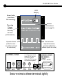
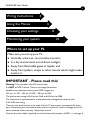
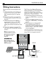
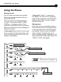
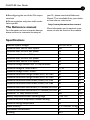
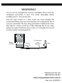
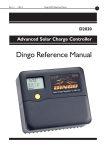
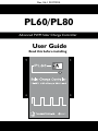
Rev. U6.1 01072014 PL60/PL80 Advanced PWM Solar Charge Controller User Guide Read this before installing PL60/PL80 User Guide 2 LCD Display Screw holes (use these for mounting) Button (instructions are on page 5) Mounting Flange (mount vertically for best performance) Expansion Socket (under the cover see reference manual for instructions) Connection for temperature sensor, generator and battery sensors (under the cover) CONNECTIONS The G Terminals are a pair of voltage free contacts. When ACTIVE they are connected together. When INACTIVE they are not connected together. + - - + WZS SOLAR BATTERY BATT. CABLE NEG. NEG. POS. G CONTACT 0.3A MAX G CONTACT 0.3A MAX TEMP SENSOR TEMP SENSOR + B- SENSE BATTERY + SENSE - + SOL. POS. LOAD POS. NEG. Screws on side of the lid must be in place during transport. Secure wires to these terminals tightly PL60/PL80 User Guide Wiring Instructions 3 4 Using the Menus Choosing your settings Monitoring your system 6 8 10 Where to set up your PL Make sure you set up your PL: Vertically, where air can circulate around it; In a dry environment out of direct sunlight; Away from flammable gases or liquids; and Away from spiders, wasps or other insects which might make nests in it. IMPORTANT - Please read this! Warning: This controller is for DC current only. It is NOT an MPPT device. There is no voltage conversion. Suitable array maximum power point (MPP) ranges are: 12V sys 16-19V, 24V sys 32-38V, 48V sys 64-76V The load current rating is 30A for the PL60 and 40A for the PL80. The G terminal is implemented as a solid state relay (voltage free contacts) with 0.3A,100V max rating There are two small screws in the sides of the lid. These screws are essential for transport. Transporting the unit without these screws in place will result in damage which will not be covered under warranty. Keep these screws!. Connect the catch diode (supplied) across load terminals (stripe to LOAD +) -see page 4 PL60/PL80 User Guide 4 Wiring Instructions Wires should be connected tightly as follows: a.Connect the fuse* on the positive (+) terminal of the battery to the “BATT POS” terminal on your PL. (See diagram). b.Connect the positive (+) terminal of the solar panel to the SOL POS. terminal of PL. c. Connect the fuse on the negative (-) terminal of the battery to the “BATTERY NEG” terminal of the PL. The display panel of the PL should then start up. d.Connect the negative (-) terminal of the solar panel to the “SOLAR NEG” terminal of the PL. Note: if using this PL in a motorhome or vehicle, please see our website for suggested wiring diagrams. The PL has a Low Battery Disconnect feature (see page 10), which disconnects equipment powered by your battery (known as a “load”) if the battery voltage gets too low. To use this feature: e.Connect the positive terminal of your load to the LOAD POS(+) terminal on the PL. f. Connect the negative terminal of your load to the “LOAD NEG(-)” terminal of your PL. g.Some equipment can damage the PL when a load disconnect occurs. To prevent this, connect the diode (supplied) between battery + and LOAD- as shown in the wiring diagram. *Australian Standards recommend that you connect an appropriate fuse to each terminal of the battery. Fuses are not supplied with the PL. WARNING Never connect an inverter or battery to the LOAD terminal LOAD - - + Fuse SOLAR - + BATTERY BATTERY Fuse + Supplied diode (stripe to bat +) Fuse PL60 Max. 30A PL80 Max. 40A PL60/PL80 User Guide 5 Using the Menus Moving around You can move around the menu system and change settings using the button on the front of the PL. There are seven top-level menu items in the PL’s menu system (BATV, CHRG, LOAD etc - see diagram below). Each menu item provides access to a sub-menu, and some of these sub-menus lead again to further sub-menus. A short-push advances the PL to the next menu or setting. To do a short push, press on the button on the front of the PL, and release it immediately. A long push “selects”, to move into a sub-menu or to allow you to change settings. To do a long push, press the button, holding it down until the menu changes (about one second). Getting back Wherever you are in the menu system, a series of short-pushes will bring you back to the top-level menus without changing any settings. There are two exceptions: when a number is flashing (you are already changing a setting - see page 6); and when you see the word “EXIT” (you’re in “History” mode - see page 8). BATV Regulator State CHRG CINT CEXT Generator Control LOAD LINT LEXT Low Battery Disconnect IN INT EXT Clear Clear INT EXT Clear Clear OUT DATA SET Thin arrow=short push Thick arrow=long push VMAX VMIN FTIM SOC TEMP SOLV TIME VOLT PROG BCAP Set Set Set Set HIST History Data 6 PL60/PL80 User Guide Choosing your settings You must follow the procedure below to ensure that your PL will charge the battery correctly. 1. Set the Time a.Short-push until the display shows “SET”. b.Long-push once, and the display will show “TIME”. c. Long-push again, and the time will start flashing. (Note that the time is displayed in hours and tenths of hours. For example, “6.5” means 6:30am, and “13.1” means 1:06pm.) d.Short-push until the time shown is correct. If you go past 23.9, it will cycle back to 0.0 (midnight). e.When the time shown is correct, longpush to set it. 2. Set the System Voltage a.After setting the time, short-push to move from “TIME” to “VOLT”. Longpush, and the voltage will start flashing. b.Short-push until the voltage is correct for your battery. If you pass 48V, it will cycle back to 12V. c. When the battery voltage is correct, long-push to set it. 3. Set your program The PL comes with a number of pre-set programs, to make configuration easy for most installations. a.After setting the battery voltage, short-push to move from “VOLT” to “PROG”. b.Long-push once, and the program number will start flashing. c. Short-push to set your program: PROG 0: Liquid Electrolyte (Flooded) batteries with Low Battery Disconnect PROG 1: Gel/AGM (Sealed) batteries with Low Battery Disconnect. PROG 2: Liquid Electrolyte (Flooded) batteries with Low Battery Disconnect and Light Controller option (see pg 10). PROG 3: Gel /AGM (Sealed) batteries with Low Battery Disconnect and Light Controller option. PROG 4: Customised setup. Choosing this program will require you to set a number of additional parameters. See page 11 for more information. d.When the program shown is correct, long-push to set it. Programs 0-3 are generic programs for different battery types. Consult your battery supplier for the settings recommended for your battery 4. Set the Battery Capacity a.Short-push to move from “PROG” to “BCAP”. b.Long-push once, and the battery capacity will start flashing. c. Short-push to choose the correct battery capacity for your system in Ampere hours (Ah). (Large settings display in thousands - eg. 1600 Ah shows as “1.6”.) If you are unsure, check your battery manual or consult your battery supplier. d.Long-push to keep the chosen value. PL60/PL80 User Guide 7 Monitoring your system The PL’s advanced monitoring functions provide you with unparallelled information about your system. Here are some of the questions your PL can answer: How full is the battery? The voltage level of your battery is an approximate measure of how full it is, and is shown on the top-level “BATV” screen. Alternatively, SOC in the DATA sub-menu (long-push on DATA, then three short-pushes) uses the amp-hour data to provide an educated guess of the state of charge. (Warning: SOC will be useless if the PL is not measuring all the charge and discharge from the battery. For example, if an inverter is connected directly to the battery, an external shunt (with a PLS2 Shunt Adapter) is needed so that the PL can include the inverter in its calculations.) How much energy have I collected today? The top-level IN screen shows how many Amp hours have been collected today. How much energy have I used today? The top-level OUT screen shows how many Amp hours the load has used today. What voltage did the battery reach? VMAX shows today’s maximum voltage since midnight; VMIN shows today’s minimum voltage. Both are in the DATA sub-menu. Are components working correctly? An optional temperature sensor can be connected to your PL to improve the battery charging accuracy. If this sensor is installed, the battery temperature is shown on the TEMP screen in the DATA sub-menu. To test your solar array, SOLV in the DATA menu shows the open-circuit voltage the solar array is generating. The LCD Screen Extra system information can be obtained from words that appear along the bottom of the LCD screen. Boost: The PL is in the BOOST phase of its charge cycle. Load: The PL has turned off the load output due to low battery voltage (if the low battery disconnect function is enabled). Gen: The PL has turned on the ‘G’ output to activate a generator (if this function is enabled). PL60/PL80 User Guide 8 Retrieving historical data In addition to storing today’s performance data, the PL keeps information about the last 30 days of operation. Historical performance information can be accessed from the DATA screen (see diagram below). After a long-push on DATA, short-push until you see HIST. A long-push on HIST will put you in “history mode”, where you can cycle through each day’s data. (Note that the day numbers go backwards - i.e. DAY 1 means yesterday, and DAY 30 is 30 days ago.) Quick Summary IN The amount of energy collected in Amp hours OUT The amount of energy used in Amp hours VMAXmaximum battery voltage since midnight. VMIN minimum battery voltage since midnight. FTIM time of day the PL entered the Float state (see page 9). SOC Percentage estimate of the state of charge of the battery based on the amp hours. A very rough ‘fuel gauge’. TEMPtemperature being sensed by the external temperature sensor (if attached). SOLV solar panel voltage (open circuit). NB - the PL stops charging the battery while displaying this screen. HIST entry point for history data. At midnight, IN, OUT, VMAX, VMIN, FTIM, and SOC are stored in the history data and reset. VMAX and VMIN respond very slowly to changes in battery voltage. This allows them to ignore short term voltage fluctuations. Thin arrow=short push Thick arrow=long push BATV VMAX VMIN FTIM SOC TEMP SOLV HIST CHRG LOAD IN OUT DATA DAY1 IN OUT VMAX VMIN FTIM SOC NEXT BACK EXIT DAY2 DAY30 DATA DAY2 IN OUT VMAX VMIN FTIM SOC NEXT BACK EXIT DAY3 ... IN OUT VMAX VMIN FTIM SOC DAY3 NEXT DAY1 BACK DATA EXIT ... ... ... ... ... ... DAY4 DAY2 DATA DAY30 IN OUT VMAX VMIN FTIM SOC NEXT BACK EXIT SET PL60/PL80 User Guide 9 The battery charging process When charging your battery, the PL moves automatically through the following charging sequence: Boost phase - In this phase, all available charge is used to charge the battery as quickly as possible. When the battery is charging in the Boost phase, the “Boost” indicator appears on the PL’s screen. Absorption phase - The battery is nearly full. To avoid excess gassing, the charge current is now adjusted to keep the battery voltage constant. Float phase - The battery is fully charged, so the PL now monitors the battery and keeps it full. If the battery voltage drops below a pre-set point, the battery will move back to the Boost phase automatically. To increase battery life, the PL will occasionally move into an additional phase called the Equalisation phase. This phase levels the charge between the different cells inside the battery by overcharging the battery for a short period. The PL moves through these phases automatically, but it is also possible to change the phase manually. A long-push on the BATV menu will show the current charging phase. Subsequent long-pushes will move the PL into the next phase in the cycle.The diagram below shows how the voltage of the battery varies throughout the charging process. The battery charging settings shown in the diagram (BMAX, ETIM etc) can all be set individually in Program 4 This means the PL can be adjusted to charge well even in unusual installations. For more information about doing this, see page 11. In most cases, the pre-set values provided by choosing Programs 0, 1, 2 or 3 will be ensure good charge control without a complex setup process. The Battery Charge Cycle EMAX TIME BATTERYVOLTAGE Fig.2 BatteryChargeCycle BMAX ABSV ETIM FLTV ATIM BRTN BOOST EQUALISATION ABSORPTION FLOAT BOOST 10 Low battery disconnect Low Battery Disconnect is a feature of the PL which helps avoid battery damage by preventing the load from excessively draining the battery. You do not have to use this feature - the PL will still charge the battery properly. Low Battery Disconnect works by turning the load off when the voltage falls below a pre-set point for a period of time. This feature is designed not to trigger if the battery voltage drops for just a few moments (for example, because a motor has just been turned on). Once the battery has recharged to a safe level, the load will automatically switch on again. To use Low Battery Disconnect, you need to connect your load to the PL as described on page 4. In Programs 0-3, Low Battery Disconnect is always enabled. Note - NEVER connect batteries or inverters to the LOAD terminal of the PL. They will cause heavy current flow which will damage the PL. Light controller option The Light Controller is an additional optional function of the PL. It can be used to automatically switch lights on during darkness. When the voltage from the solar array drops, the Light Controller function will switch on power to the PL’s LOAD terminal. If you have connected lights to the PL’s LOAD terminal, the PL will switch on the lights at dusk and switch them off at dawn. To use the Light Controller option, choose a PL program which enables this function, as described on page 6. You should then PL60/PL80 User Guide wire your lights to the LOAD terminal as described in parts (e) and (f) on page 4. Note that if the battery’s voltage falls below a pre-set level, the Low Battery Disconnect function will protect the battery by switching off the lights even if it is dark. Optional accessories The following optional accessories are also available for the PL: Battery temperature sensor (PLT and PLTB) Plug-in shunt adapter (PLS2) which, with shunts, allows the PL to incorporate an inverter or backup generator in its calculations, and to measure currents of up to 250A Interface for remote control via a computer and a modem (PLI) Remote Display (PLM) Other features The PL has a number of features which are not described in this User Guide. These include: Fully customisable regulation settings via Program 4. Controlling equipment such as sprinklers, pumps, lights etc. Controlling a backup generator Charging a second battery Triggering an alarm when the battery is low Temperature compensation Disabling tampering via a lockout setting PL60/PL80 User Guide Reconfiguring the use of the PL’s output terminals Shunt regulation and pulse width modulation options The Reference manual For information on how to use the features above and how to customise the setup of 11 your PL, please consult the Reference Manual. This is available from your dealer or from the our web site at: http://www.plasmatronics.com.au/ More information on the optional accessories can also be found on the website. Specifications Nominal System voltages 12,24,32,36,48 V Maximum solar Voc for a 48V system 100 V Minimum solar Voc for a 48V system 76 V Maximum solar Voc for a 24V system 80 V Minimum solar Voc for a 24V system 38 V Maximum solar Voc for a 12V system 70 V Maximum voltage between the “G”relay terminals 85 V Maximum voltage B- sense to BAT- +/-10 V Maximum voltage LOAD- to BAT- 75 V Maximum continuous charge current (SOL-) for PL60 60 A Maximum continuous charge current (SOL-) for PL80 80 A Maximum continuous load current (LOAD-) for PL60 30 A Maximum continuous load current (LOAD-) for PL80 40 A Maximum short term load current (<5 minutes) for PL60 40 A Maximum short term load current (<5 minutes) for PL80 50 A Maximum “G” relay contact current 300 mA Battery temperature sensor operating range -5 to +50 °C Maximum ambient temperature without derating 50 °C °C Maximum storage temperature 70 Meter accuracy <+/-2% FSD +2 dig Termination stud diamater 6 IP Rating IP22 mm WARNING! Your PL can be damaged by incorrect installation! Please read the installation instructions in your User Guide thoroughly before installing your PL. Also, please note: Excessive load current or a short circuit can cause damage. We recommend fitting a fuse (or circuit breaker) of an appropriate size to suit your actual load. The fuse rating (slow blow) should not be more than 30A for a PL60 or 40A for a PL80. Although the PL has some protection against brief load short circuits, an accidental short circuit of a few seconds can damage the PL. Charge Controller Fuse will protect PL **If wires touch it can damage PL Load Plasmatronics Pty Ltd ABN 98 073 758 497 http://www.plasmatronics.com.au Rev. U6.1 01072014