1
Dimensions:
2.47 x 2.47 x 0.63 inches (62.7 x 62.7 x 16 mm)
Weight:
0.75 oz (21 g)
Materials:
Fiberglass printed circuit board
3. MAKING CONNECTIONS
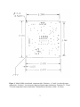
Circuit board geometry and connector locations are shown in Figure 1. Your tilt sensor
connects to the board at the pins marked (−), E and (+). The tilt sensor wires corresponding to these
positions are defined in the user’s manual for your tilt sensor.
Power input and signal output connections are made at the pins marked 1, 2, 3, 4, 5 and 6
(Figure 1). Pin designations and wire color coding of the connector assembly shipped with your
signal conditioner are defined in the table below. For additional information on recording your
signal, see Appendix B. WARNING! Do not connect your tilt sensor to pins 1-6. Sensor damage
not covered by the warranty will result!
Pin
Function
Wire Color
1
2
3
4
5
6
DC power in
Signal ground
Power ground
+Tilt out
- Tilt out
Temperature out
red
white
black
green
blue
yellow
In the standard Model 84800 the temperature sensor is soldered to the circuit board at the
“X” locations T1, T2 and T3 (Figure 1). If you are using a temperature sensor that plugs into the
circuit board, the wire colors corresponding to the T1, T2 and T3 positions can be found in the user’s
manual for your tilt sensor package.
4. GROUNDING AND TRANSIENT PROTECTION
Signal and power ground (pins 2 and 3, Figure 1) are common on the circuit board.
However, if you plan to measure single-ended tilt or temperature at a distance more than several
meters away from the board, it is a good idea to measure the tilt signal (pin 4) and the temperature
signal (pin 6) with reference to a wire connected to signal ground (pin 2). Run a separate power
ground wire to your power supply from pin 3. Do not connect signal and power grounds at the
power supply. With this wiring arrangement no current flows in your signal ground wire. The
output voltage should therefore be the same at your measurement point as on the Model 84800
circuit board.
2